
Subscribe to Our Youtube Channel
Related Manuals for Gossen MetraWatt Metraline ZCheck


Summary of Contents for Gossen MetraWatt Metraline ZCheck
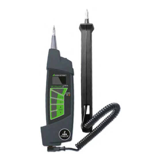
- Page 1 Operating Instructions CHECK METRALINE 3-349-697-03 Loop Resistance Measuring Instrument 2/4.13 1.800.561.8187 information@itm.com www. .com...
-
Page 2: Table Of Contents
Table of Contents Page Meanings of Symbols on the Instrument Introduction ..............2 This device is equipped with double or reinforced insulation. Scope of Delivery ................2 Optional accessories ..............2 Safety Precautions .................2 Danger of injury due to electrical current, General Device Description .............3 warning regarding dangerous electrical voltage Applicable Standards ..............3 Warning concerning a source of danger... -
Page 3: General Device Description
Exclusion of Liability Applicable Standards When testing systems with RCCBs, the latter may switch off. This Measurement Safety may occur even though the test does not normally provide for it. EN 61557-1 EN 55022 class B EN 61010-1 Leakage currents may be present which, in combination with the EN 61557-3 EN 61326-1 EN61010-031... -
Page 4: Initial Start-Up
Control Panel pressed and no voltage has been applied to the test probes dur- ing this time. 1 Graphic OLED Display 2 START key: Instructions and Principles with Validity for All – Switch on: Measurements Press and hold until the •... -
Page 5: Measurement Of Fault Loop Impedance And Line Impedance
Measurement of Fault Loop Impedance and Line Imped- ance 3.3.1 Measurement in Circuits without RCD – Function The “~” function is suitable for measuring fault loop impedance in electrical circuits without RCCBs, as well as line impedance. ➭ After switching the instrument on, connect it between L and PE in order to measure fault loop impedance, and between L Figure 3.8: High Temperature Display... -
Page 6: Measurement In Electrical Circuits With Rcd
3.3.2 Displaying Further Measured/Calculated Values 3.3.3 Measurement in Electrical Circuits with RCD Testing Without Tripping the RCCB Stated briefly: The following are displayed, one after the other, by ▲ ▼ Select the “RCD” function if loop impedance needs to be mea- pressing the DISP and DISP keys:... -
Page 7: Automatic Evaluation Of Measured Impedance
Automatic Evaluation of Measured Impedance Further Device Functions Automatic evaluation is only possible with the detailed representa- Phase Detection tion. If the symbol appears in the lower right-hand corner of the • Protective device parameters are stored to memory or to the display (see figures 2.4 and 2.5), and if a phase is contacted with database. -
Page 8: Technical Data
Technical Data General Data Reference Conditions Individual Device Functions Temperature 23 ± 2° C Fault Loop Impedance / Line Impedance Relative humidity 40 to 60% Nominal Range per EN 61557-3: 0.27 to 200 Line voltage 230 V 2% / 50 Hz Device position Range... -
Page 9: Table Of Protective Devices Stored To The Instrument
Table of Protective Devices Stored to the Fuse Type C Instrument Nominal Disconnecting Time [s] Current Fuse Type NV Min. Short-Circuit Current (A) Nominal Disconnecting Time [s] Current Min. Short-Circuit Current (A) 32.5 22.3 18.7 15.9 10.8 65.6 46.4 38.8 31.9 18.7 21.6... -
Page 10: Maintenance
Maintenance Safety Precautions • Do not attempt to recharge alkaline batteries: they may leak, Device Power Supply explode etc. The test instrument may be severely damaged or destroyed as a result. • After initially charging new batteries and after rechargeable Caution: Dangerous Voltage! batteries have not been used for a lengthy period of time (sev- Dangerous voltage in battery compartment!
Need help?
Do you have a question about the Metraline ZCheck and is the answer not in the manual?
Questions and answers