Table of Contents
Advertisement
Quick Links
Advertisement
Table of Contents

Subscribe to Our Youtube Channel
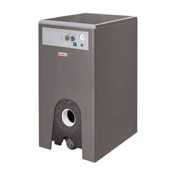
Summary of Contents for Fondital ELBA DUAL
- Page 1 IST 03 C 202-03 ELBA DUAL INSTALLATION, USE AND MAINTENANCE...
- Page 2 Thank you for choosing our boilers. Please read these installation and maintenance instructions with care. Please note that the boiler must only be installed, repaired and serviced by qualified personnel.
-
Page 3: General Information For Installers, Service Engineers And Users
General information for installers, service engineers and users This INSTRUCTION MANUAL, which To guarantee efficiency and correct is an integral and indispensable part operation of the boiler, it is legally of the product, must be handed binding to service the boilers once a year according to the schedule over to the user by the installer indicated in the relevant section of... -
Page 4: Table Of Contents
Table of contents To the user ..............................page General information for installers, service engineers and users ..........page 1 Instructions for the user ........................page 1.1 Control panel ..........................page 1.2 Boiler operation ..........................page 1.2.1 Switching on ........................page 1.2.2 Burner shutdown ...................... -
Page 5: Instructions For The User
1 Instructions for the user 1.1 Control panel pic. 1 A - Main switch with power light D - Overheating shutdown light (red) E - Burner light (yellow) (green) B - CH temperature control F - Thermometer C - Heating pump operating light G - Safety thermostat with manual (yellow) reset... -
Page 6: Boiler Operation
1.2 Boiler operation (pic. 1) 1.3 Maintenance It is a legal requirement to have the 1.2.1 Switching on boiler and the burner serviced once * Open the fuel tap. a year. * Turn the boiler main switch A to If the boiler is serviced regularly, it the ON position (the light comes will optimise efficiency, safeguard on). -
Page 7: Technical Features And Dimensions
2 Technical features and dimensions 2.1 Technical features This is a floor-standing gas or oil The main technical features of the * Designed for connection to a boiler with a cast iron heat exchanger boilers are listed below. remote D.H.W. storage tank control with 3 smoke passes, working with board (optional kit) oil or gas free-standing blown-air... -
Page 8: Dimensions
2.2 Dimensions pic. 2 MODEL Flow A Return B 1" 1/4 1/4" 1" 1/4 1/4" 1" 1/4 1/4" 1" 1/4 1/4" 1" 1/4 1/4" 1" 1/4 1/4"... -
Page 9: Technical Characteristics
2.3 Technical characteristics MODELS EC efficiency rating Max. heat output Heat input 26.6 36.3 47.2 57.9 68.5 79.3 Efficiency at nominal load 91.5 Efficiency at reduced load (30%) 89.7 90.7 90.7 91.1 91.6 91.6 No. -
Page 10: Instructions For The Installer
3 Instructions for the installer 3.1 Installation standards from the room in which the boiler is failure to follow the above rules. installed. Proceed as follows to install the boiler: The boiler must be installed in compliance with current laws and standards which are considered an - Unscrew the four screws securing integral part of this handbook. -
Page 11: Choosing And Installing The Burner
* The chimney must be as vertical as * Measure the combustion air there must be no infiltration of air possible, and have a constant cross temperature. along the pipe leading from the section and no throttling. * Measure the flue gas temperature tank. -
Page 12: Hydraulic Connection
The Manufacturer declines all - Gradually open the water inlet tap 3.4.2 Switching on and off liability for damage or injury and check that the relief valves in the resulting from failure to earth the system, if there are any, are working Refer to the "User Instructions"... -
Page 13: Wiring Diagrams
3.5 Wiring diagrams 3.5.1 Boiler layout CH pump feeding Room thermostat connection Water pressure switch connection Electric feeding pic. 8 3.5.2 General layout light blue blue black brown grey green purple yellow yellow/ green pic. 9... -
Page 14: Topographical Layout
3.5.3 Topographical layout (1) PR1 R2-1 R1-3 R1-4 PCB 1 R1-1 R1-2 230Vac 50Hz R6-4 R2-3 R6-3 R2-2 R6-1 R5-2 R6-2 R5-1 R2-4 R4-3 R2-5 R4-2 R3-3 R7-1 R3-2 R7-2 R3-1 R8-1 R8-2 R2-6 R2-7 R3-4 R3-5 R3-6 R4-1 pic. 10 Key to symbols: Minimum temperature thermostat (optional) [on the printed circu- it it is indicated with Tm]... -
Page 15: Maintenance
4 Maintenance - boiler combustion parameters Do not clean the heat exchanger through flue analysis. with flammable products such as petrol or solvent. Individually-installed boilers need to be checked once every two years, cascade boilers need to be checked once a year. When remounting the front panels, - condition and tightness of the flue check the state of the seals and... - Page 16 25079 VOBARNO (Brescia) Italy - Via Cerreto, 40 Tél. +39 0365/878.31 Fax +39 0365/878.304 e-mail: info@fondital.it www.fondital.com The MANUFACTURER reserves the right to implement any necessary and/or useful variation to products, without modifying fundamental characteristics Uff. Pubblicità Fondital IST 03 C 202 - 03 Febbraio 2018 (02/2018)


Need help?
Do you have a question about the ELBA DUAL and is the answer not in the manual?
Questions and answers