Table of Contents
Advertisement
Advertisement
Table of Contents

Related Manuals for Fondital NOVA FLORIDA DELFIS-ANTEA Condensing Series


Summary of Contents for Fondital NOVA FLORIDA DELFIS-ANTEA Condensing Series
- Page 1 DIDACTIC MANUAL Wall-hung condensing FAMILY: boilers Instantaneous type GROUP: with forced draught Delfis-Antea MODELS: Condensing VERSIONS: For indoor installation PART NO.: AST 14 C 258/00 ______________________________________________ 1st Edition, February 2013...
-
Page 2: Table Of Contents
Contents SECTION 1 TECHNICAL CHARACTERISTICS 1.1 – Models 1.2 – Overall Dimensions 1.3 – Technical Specifications ___________________Page SECTION 02 CONTROL PANEL AND DIAGNOSTICS 2.1 – User's Interface 2.2 – LCD 2.3 – Boiler Status and Fault Codes ___________________Page SECTION 03 HYDRAULIC DIAGRAMS AND COMPONENTS 3.1 –... - Page 3 ________________________________________________________________________________ AST 14 C 258/00...
-
Page 4: Technical Characteristics
SECT. 1 TECHNICAL CHARACTERISTICS 1.1 MODELS DELFIS-ANTEA Condensing KC 24 – 28 DELFIS-ANTEA Condensing KRB 12- 24 - 28 ABBREVIATION KEY condensing combined heating-only, with internal three-way valve for integration with DHW tank heater MAIN CHARACTERISTICS DELFIS-ANTEA Condensing Line Tech KC 24 - 28: Condensing combined instantaneous boiler for indoor installation, domestic hot water + heating, s ealed chamber, forced draught, mono-thermal with plate exchanger. - Page 5 ________________________________________________________________________________ AST 14 C 258/00...
- Page 6 INSTALLATION TEMPLATE ________________________________________________________________________________ AST 14 C 258/00...
-
Page 7: Technical Specifications
1.3 TECHNICAL SPECIFICATIONS General Characteristics KC-KRB KC-KRB KRB 12 Operating parameters Equipment category II2H3P Burner nozzles n° Minimum CH circuit flow rate CH circuit min. pressure CH circuit max. pressure DHW circuit min. pressure DHW circuit max. pressure DHW specific flow rate ∆t 30°C l/min 13,5 Double flow probe triggering temperature OFF... - Page 8 Design data and chimney sizing KRB 12 Pmax. Pmin. Carico al 30 % Casing heat loss with burner off 0,55 Casing heat loss with burner on 0,26 7,78 Flue system heat loss with burner on 2,64 1,92 Flue (natural gas) mass flow 8,25 0,89 Flue gas temp.
- Page 9 Settings KRB 12 Heat Thermal Power Supply Nozzle Flue gas capacity MIN-MAX pressure diameter MIN-MAX (kW) (kW) (mbar) (mm) gas metano 3,05 9,3 ÷ 9,0 1,8 – 11,6 (60-80°C) gas propano 2,1 – 12,7 (30-50°C) 10,3 ÷ 10,0 KC-KRB 24 Heat Thermal Power Supply...
-
Page 10: Control Panel And Diagnostics
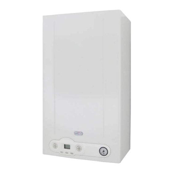
SECT. 2 CONTROL PANEL AND DIAGNOSTICS 2.1 USER'S INTERFACE 1. Set domestic hot water temperature These keys are used to set (increase or decrease) the domestic hot water temperature within a range from 35°C to 60°C. 2. Recall information and confirm parameters This key is used to scroll the sequence of the values of some parameters (see following paragraphs). - Page 11 2.2 LCD a. Flue cleaning function indicator It illuminates flashing when the flue cleaning function is enabled by pressing keys 2 and 4 at the same time (see previous paragraph). When this function is ON, boiler flow temperature and fan rpm are displayed. b.
-
Page 12: Boiler Status And Fault Codes
2.3 BOILER STATUS AND FAULT CODES Normal operation Boiler in STANDBY mode. Boiler in SUMMER mode No active function The flow water temperature is displayed Boiler in SUMMER or WINTER mode No active function The flow water temperature is displayed Boiler in CENTRAL HEATING ONLY mode No active function The flow water temperature is displayed... - Page 13 Boiler shutdown due to flame absence Boiler shutdown due to double flow probe triggering Boiler shutdown due to flue gas thermostat triggering Boiler shutdown due to water pressure switch triggering Boiler shutdown due to flow probe fault Boiler shutdown due to DHW probe fault Boiler shutdown due to flue gas probe fault Boiler shutdown due to failure of the tank heater probe (KRB) External probe fault (a)
- Page 14 No communication between additional boards (f) Plumbing configuration not allowed Shutdown due to safety circuit hardware failure Boiler shutdown due to ∆T max deviation error Shutdown due to heating fluid circulation malfunction* (r) or (f) Shutdown due to heating fluid circulation malfunction* (r) or (f) Shutdown due to heating fluid circulation malfunction* (r) or (f)
- Page 15 Malfunction, errors that can be reset by technical service only To reset particularly serious shutdowns (see following table) it is necessary to call the technical service. It is necessary to contemporaneously press the three keys indicated below. Then the wrench icon is displayed and this indicates the possibility to reset the boiler with the usual "reset"...
-
Page 16: Hydraulic Diagrams And Components
SECT. 3 HYDRAULIC DIAGRAMS AND COMPONENTS 3.1 HYDRAULIC DIAGRAMS 1. Condensate trap 20. 3-bar safety valve 2. Modulating gas valve 21. Discharge tap 3. CH temperature probe 1 22. Minimum pressure switch 4. CH temperature probe 2 23. 13-14 l/min flow-limiting device 5. - Page 17 1. Condensate drain trap 17. Fan control sensor 2. Modulating gas valve 18. De-aerator 3. Heating temperature sensor 1 19. Circulating pump 4. Heating temperature sensor 2 20. 3-bar safety valve 5. Modulating fan 21. Discharge tap 6. Return temperature sensor 22.
-
Page 18: Hydraulic Unit
3.2 HYDRAULIC UNIT MOTORISED THREE-WAY VALVE The boiler uses a three-way valve to divert the water flow into another pipe. Its function consists in diverting the primary circuit water into the secondary exchanger where heat will be transferred to the DHW. It consists of one main brass valve body, one plastic cartridge, and one electric motor (actuator) to move the internal shutter. - Page 19 Three-way valve section: CARTRIDGE THERMOPOLYMERS SHUTTER ACTUATOR 3-WAY STATUS Domestic hot water Shutter upwards Actuator piston in rest position Central heating Shutter downwards Actuator piston in working position The boiler is provided with an automatic by-pass with non-return valve whose opening threshold is of 400 mbar .
- Page 20 The circulation pump end block features one 3-position selector to set the motor rotation speed and thus the head to the system. The circulating pump is the same for both power rates, what changes (according to the primary exchanger) is the residual head curve: 12 kW 24 kW...
- Page 21 DHW FLOW SWITCH The domestic hot water flow switch features a magnet switch whose position determines the minimum quantity of hot domestic water necessary to start the boiler (3 l/min ON and 1 l/min OFF). If the request of DHW does not exceed such value the micro-switch does not close the contact and inhibits the boiler starting to avoid the boiling risk.
- Page 22 EXPANSION VESSEL An increase of the heating water inside a closed circuit corresponds to an increase of the water volume. As no further space is available, it will not be water volume - but pressure - to increase. If pressure value exceeds safety valve triggering point, this latter will open and discharge water from system.
-
Page 23: Primary Condensing Exchanger
3.3 PRIMARY CONDENSING EXCHANGER The exchanger consists of stainless steel spiral pipes with oval section which are coiled during the working phase. No welding is present in the exchanger hot zones (in contact with the flame); the exchanger features a weak heat inertia and a high resistance against corrosion. The outer coating is made of thermo-polymer plastic materials. - Page 24 Inside the module, the system return pipe is placed in the coldest zone (condensing chamber) to ensure flue gas condensing and water pre-heating so that the water temperature is higher when flowing into the combustion chamber. This decreases the fuel consumption and avoid condensate formation that would drop onto and damage the burner.
-
Page 25: Pre-Mixed Burner
3.4 PRE-MIXED BURNER The stainless steel burner with cylindrical shape is fixed to the exchanger by means of an aluminium flange. Inside the flange there is a silicone seal (to be replaced every two years upon maintenance) and a flue gas and condensate sealing rope, whereas a ceramic fibre insulating material prevents it from overheating. -
Page 26: Gas Valve And Fan Unit
3.5 GAS VALVE AND FAN UNIT When the fan is powered it generates a vacuum along the fan-gas valve connection pipe according to the air flow passing through it. When the gas valve is powered, on the outlet there will be a negative pressure, and the valve will regulate the gas flow rate according to such vacuum and the fan speed. - Page 27 MODULATING FAN The fan ensures a constant air flow during the modulation range from the maximum to the minimum heat capacity. The fan speed changes according to the modulation power provided by the board as well as the type of boiler specified in the chart below. This speed variation is due to the heat request and the temperature detected by the DHW and heating NTC probes.
- Page 28 SIT 848_135 GAS VALVE GAS OUT Minimum power adjuster screw Maximum power adjuster screw Compensation pressure point Pressure measurement point Gas inlet GAS IN Gas valve features SIT 848_135 SV1 and SV2 safety coil operating power supply 230 VAC 50 Hz SV1 operating current 40 mA SV2 operating current...
- Page 29 The valve features a compensation pressure point connected to the combustion chamber through a silicone pipe. Valve thus knows the pressure on nozzles and can supply the correct quantity of gas even in case of overpressure or vacuum inside the chamber. Upon ignition, for example, when fan is activated a vacuum develops inside the combustion chamber, and valve (thanks to this pressure point) decreases nozzle pressure so as to balance any exceeding gas supply due to vacuum.
- Page 30 AIR/GAS MIXING UNIT The air/gas mixture is generated thanks to the air flow through the vacuum developed by the fan and sent to the gas valve mechanism. When the fan is powered it creates a vacuum proportional to its speed ensuring a mixture with constant ratio from the maximum to the minimum power.
- Page 31 3.6 FLUE GAS VENTING AND CONDENSATE DRAIN SYSTEM The boiler is equipped with a tower for intake/discharge duct connection; the tower features openings directly accessing air and flue gas ducts (Openings for combustion efficiency measurement). To take the measurements it is necessary to remove the metallic protective plate (A) and insert the analyser flue gas probe in the right hand opening.
-
Page 32: Gas Setting And Tsp Parameters
SECT. 4 GAS SETTING AND TSP PARAMETERS 4.1 GAS VALVE SETTING To set the gas valve, proceed as follows: check mains static pressure by means of the inlet pressure management point referring to the "setting" table on page 8 (pressure values lower than the required ones do no ensure a proper operation of the boiler);... -
Page 33: Chimney Sweep Function
4.2 CHIMNEY SWEEP FUNCTION The boiler features a flue cleaning function which must be used to measure combustion efficiency during operation and to set the burner. This function can be enabled only in the HEATING + DOMESTIC HOT WATER operating mode. -
Page 34: Gas Conversion
4.3 GAS CONVERSION Our boilers are manufactured to run on the type of gas (natural gas or propane) specified on the purchase order. Subsequent conversion requires the intervention of a qualified service engineer. Gas conversion procedure. First disconnect the boiler from the power supply, and the turn off the main gas cock. - Page 35 4.4 PARAMETERS The boards house a memory with a series of parameters (called P parameters) to be accessed for displaying purposes only, or to be edited for boiler perfect setting based on the system used. These parameters can be directly accessed from user's interface, or through the remote control.
- Page 36 Parameter list Default Parameter Range Notes value 0 = 12 kW natural gas 1 = 24 kW natural gas 2 = 28 kW natural gas 3 = 24 kW LPG Boiler output selection 4 = 28 kW LPG 5 = 12 kW LPG 0 = EBM 1 = FIME Fan type selection...
- Page 37 0-99 s Ambient / OT thermostat reading delay 0 = shutdown and fault 1 = TA1 remote relay 2 = solar relay Multifunction relay setting 3 = TA2 request not available in this version Select solar function 10-90°C 60°C Tank heater set-point range 1-30°C 6°C ∆T ON (solar pump ignition diff.)
- Page 38 It can be displayed with two Display of current flow temperature for connected zone boards zone 3 It can be displayed with Display of flow temperature set-point for three connected zone boards zone 4 It can be displayed with Display of current flow temperature for three connected zone boards zone 4...
- Page 39 It can be set with one zone board connected. 15 to 35°C 20°C Zone 2 set-point selection (fictitious temp.) Without external probe: Fixed flow set-point It can be set with two connected zone boards 0 to 3 Without external probe: Zone 3 curve selection Value <...
-
Page 40: Operating Logic
SECT. 5 OPERATING LOGIC 5.1 MAIN GENERAL CHARACTERISTICS Function priority; Boiler type setting; Ignition phase at pre-set power; Flame propagation phase at pre-set power; Automatic flame control; DHW priority; Plate DHW modulation; Ambient thermostat; ... - Page 41 BOILER TYPE SETTING This board is arranged to manage 3 different types of boiler according to the setting of parameter P3 (see paragraph on page 34): P3 = 1 combi instant plates P3 = 2 heating only (future implementation) P3 = 3 ...
- Page 42 In case of flame shutdown a post-circulation is carried out according to the operation request (30 sec. in DHW mode; P13 in heating mode with three-way valve in the relevant operation position) and a 10 second post-ventilation to clean the chamber at the ignition speed (P6) + 900 rpm.
- Page 43 PLATE DHW MODULATIONv (version KC only, P3=1) Upon an operation request in plate DHW mode with boiler in “DHW” or “DHW+HEATING”, if the water temperature read by the DHW probe is lower than the set-point value + 3°C, a consensus is given to the automatic flame control section to start the burner ignition sequence.
- Page 44 Plate DHW modulation temperatures: DHW temperature setting range: 35 °C ÷ 57 °C DHW thermostat triggering temperature OFF = set point + 5°C DHW thermostat triggering temperature ON = set point + 3°C DHW thermostat triggering temp. upon intake (first 20 sec) OFF = set point + 15° C ...
- Page 45 AMBIANT THERMOSTAT With the boiler set on the "DHW + CH" or "Hearing only" operating mode, the closing up of ambient thermostat electric contact (as well as by the remote control or the zone board) will result in a request making heating modulation start. WARNING: with parameter P16 it is possible to delay the ambient thermostat reading to allow the zone valves to open before the boiler pump starts (from 0 to 199 seconds).
- Page 46 The flow water temperature is read constantly and the ramp is interrupted when the flame modulation point is reached with a PID-type action, until the set heating temperature is reached and maintained. During the heating phase: with P28 = 0 , the pump is running and the electric (pump and diverting valve) diverting valve is in the heating position;...
- Page 47 Heating modulation temperature - reduced range (P10<1): Heating temperature setting reduced range: 20-45°C Reduced heating thermostat intervention temperature: OFF = set-point + 2°C Reduced heating thermostat intervention temperature: ON = set-point - 2°C Heating thermostat timer (anti-fast) via parameter P11: 0-10 min, default 4 min with Tflow > ...
- Page 48 Thermoregulation curve setting If keys “reset” and “- heating” are pressed together for three seconds, you will access the parameter setting mode. Use keys “+/- heating”, to select parameter P10: Press “OK” to confirm that parameter value has to be edited; the wrench symbol indicates that parameter value can be edited using keys “+/- heating”: ...
- Page 49 The curves indicated above refer to a request of a “fictitious room temperature” of 20°C. In case of required temperature different from 20°C, all curves are parallely translated. Example of curve shifting with P10=1.5 and fictitious temperature from 20 to 25°C: The choice of the curves is a procedure that can be performed with your eyes or a mathematic formula;...
- Page 50 Checking the thermoregulation curve setting It takes time to chose the best curve. Consider the following suggestions: if upon external temperature decrease the room temperature increases, it is necessary to set a curve with a lower slope, i.e. a lower curve; ...
- Page 51 P17=1 Remote reference Upon each request by the remote control (or TA1), the relay is excited: Electric connections: P17=3 Ambient thermostat reference Upon each request by the ambient thermostat TA2, the relay is excited: Electric connections: ________________________________________________________________________________ AST 14 C 258/00...
- Page 52 OPENTHERM REMOTE CONTROL PRE-SETTING The board is provided with an internal interface that allows the connection of an OpenTherm protocol-based remote control. This latter, besides serving as an ambient thermostat for its zone, allows to set some of the boiler main parameters. The remote control must be connected to the board with two non-polarized connectors protected against short-circuits.
- Page 53 RS connection and settings Regardless of the number of boards ZONE2 used, each board must be connected to the boiler board in cascade via an RS485 connection, as shown in the diagram on the right: ZONE3 BOILER BOARD ZONE4 BOILER ...
- Page 54 Wiring diagrams The heating zones 1 and 2 can be controlled by the remote control (TA1) or the ambient thermostat (TA2) that can be connected to the boiler boards; zones 3 and 4 are activated directly by the ambient thermostat connected to the relevant zone board. Zones 3 and 4 cannot support control by the safety flow line thermostat (TSM), which must be mounted in series on the pump power supply line and will not be detected as a fault.
- Page 55 The zone board also comes with a bi-colour LED showing the following indications: Green pump active; Red, quick blinking valve opening; Red, slow blinking valve closing; Green flash boards with no request; Red, very slow blinking (1s on, 1s off) communication with boiler board not working;...
- Page 56 Zone 4: Parameter P70 setting to enter the thermoregulation curve (with an external probe) or the operating range (without an external probe). Regulation via parameter P71 of the fictitious ambient temperature (with an external probe) or the set-point flow value (without an external probe) according to the selected range. Parameter P39 displays the calculated flow temperature, and parameter P40 the current one detected by the boiler probe.
- Page 57 Tank heater filling function (pump ON) The tank heater temperature is set, via parameter P19, to a value between 10 and 90°C ( default 60°C The PS solar pump is activated under the following conditions: Tsvs < P19-2°C Tscs –...
- Page 58 Heat dissipation from the collector If the solar tank heater reaches the set temperature, this function prevents the solar collectors from stagnating for a long time, which may cause them high thermal stress. For this reason, the PS solar pump is reactivated according to the following logic: Tscs >...
- Page 59 CONFIGURATION 2: Only suitable for boilers with tank heater (P3=3), where the complex solar panel system to be controlled heats solar accumulation in a forced circulation system via the pump PS and excess solar energy is dissipated through a secondary service line, via the diverting valve The system layout is shown below.
- Page 60 Tank heater filling function (pump OFF) The PS solar pump is deactivated under the following conditions: Tsbc > P19 Tscs – Tsbs < ∆T OFF (P21) Tscs < Tmin pump collector OFF (P23-5°C) Tscs > Tmax pump collector OFF (P22) Important.
- Page 61 The VM valve is powered in the heat discharge position, according to the following logic: Tscs > (P22-10°C) Tsbc > 95°C At this point (with VM on heat discharge), the PS solar pump is powered when: Tscs > Tsvs This function deactivates then PS switches off under the following conditions: Tscs <...
- Page 62 Logical operating diagram for heat dissipation / heat discharge HEAT DISSIPATION / HEAT DISCHARGE (P22-10°C) < SCS < P22 Psol = OFF SBC > 95°C VM in tank heater position P76 = 1 HEAT DISSIPATION VM in tank HEAT DISCHARGE heater position VM in heat Psol = ON...
- Page 63 Solar function characteristics When the solar pump activates, the boiler display shows the icon indicating that the pump is active. If there is a failure involving the solar tank heater probe (SBS), or the solar collector probe (SCS), the solar pumps switches off immediately and the fault is indicated on the boiler board interface and the remote control (if connected), via the associate error codes (E28 and E24, respectively).
- Page 64 Flow probe failure (E05): the burner switches off immediately and the fan runs at the ignition power. The pump runs until the fault is removed, with the diverting valve in the heating position if before the fault there was a request for heating, flow-return anti-freeze or chimney-sweep, or there were no request at all.
- Page 65 Solar probe failure (E24, E27, E28): With P18=0, if the solar tank heater probe (SBS) fails, the VM diverting valve moves to the solar-only position (no integration by the boiler). With P18=1, if the failure involves the solar tank heater probe (SBS) or the solar collector probe (SCS), the PS solar pump switches off.
- Page 66 BRUSHLESS FAN WHOLENESS CHECK The fan speed is constantly monitored to check for any fault condition. In standby status (fan in rest condition) a speed higher than 500 rpm for more than 30 seconds triggers an alarm with consequent shutdown. At the beginning of the rotation request the detected speed must be higher than 700 rpm and within the fan maximum set speed (set-point ±...
- Page 67 POST-VENTILATION FUNCTION At the end of a request for operation, the burner (if ON) is switches off immediately and the fan remains powered on for 10 seconds (post-ventilation timer). Any request for operation on CH, DHW, anti-freeze, chimney-sweep mode will have priority, and the ventilation function in progress will be forced to end immediately.
- Page 68 flame control shuts down and the burner cannot be ignited, the anti-freeze function activates pump circulation. DESCRIPTION 10°C (or after 15’ of operation, DHW anti-freeze function 5°C or if the flow temperature is > 60°C) General temperature tolerance ± 3°C Tank heater (KRB only) The tank heater NTC probe measures the temperature of the water in the tank heater.
- Page 69 SAFETY DEVICES AND FUNCTIONS 3-bar safety valve This valve is installed on DHW pipe, and checks that pressure does not exceed 3 bar as this condition would entail boiler inner problems. Should valve read a pressure higher than the allowed limit, it will open to discharge water outside.
- Page 70 Flue gas temperature check function (E89, E90 and E91 shutdown) Such function provides two check types: Flue gas probe wholeness check. It checks that with burner ON the flue gas probe detects a value higher than the return probe temperature - 15°C. If within 900 sec.
- Page 71 Return probe Double flow probe Maximum flow and return deviation check function (E80 shutdown) Such check is carried out before each burner ignition request different from the “instantaneous DHW” one. After the pump activation, wait 10 seconds and then check the temperature differential which must be between the range specified below: ∆Tmin <...
- Page 72 For a correct operation of the boiler, the minimum flow rates must comply with the values specified below: Flue gas Water side Water flow rate Power side modules to be ensured modules [kW] [l/h] 24Kw 28 kW The check is based on the difference (∆T) between the flow temperature and the return one according to the fan power.
-
Page 73: Electrical System
SECT. 6 ELECTRICAL SYSTEM 6.1 ELECTRONIC BOARD Spare part number: 6SCHEMOD30 Board characteristics Operating voltage: 170 Vac to 300 Vac Power supply frequency: 45 – 66 Hz Protection class: IP00 Protection fuse: 5x20 2AF 1.2 µA Ionisation current: Flame detection method: ionisation Type of detection: non-polarized... -
Page 74: Outer Terminal Box Electrical Connections
6.2 OUTER TERMINAL BOX ELECTRICAL CONNECTIONS All electric connections must be made using the terminal board on the back of the control panel. For the additional board (used to manage zones or complex solar systems) there is a specific location on the back of the control panel: Additional board Connections reference... -
Page 75: Wiring Diagram
Warning: for complex solar systems, the solar valve probe (SVS) must be connected to the additional board. 6.3 WIRING DIAGRAM Connecting wires to outer 1-2-3-4-5-6-7-8 9-10-11 terminal box Key: low water pressure switch NTC flue gas 10K Ohm FL/TM: flow switch MVD: motorised deviating valve NTC DHW probe 10K Ohm gas valve... -
Page 76: Vent Ducts And Pipes
SECT. 7 VENT DUCTS AND PIPES For the air intake/flue gas venting systems, specific, manufacturer approved, condensate acid-resistant pipes and systems must be used, suitable for condensing boilers. Flue gas venting pipes are to be installed tilted toward the boiler so that condensate runs toward the combustion chamber, which is designed for condensate collection and drainage. - Page 77 WARNING: Maximum allowed length, 0.75 metres. Dimensions for connection of flue gas duct to co-axial ducts ________________________________________________________________________________ AST 14 C 258/00...
-
Page 78: 125/80 Co-Axial Air/Vent Ducts
7.2 125/80 CO-AXIAL AIR/VENT DUCTS Installation type: C13 - C33 Pipe maximum length* TYPE OF PIPING MATERIAL KRB 12 KC-KRB 24 KC-KRB 28 INSTALLATION Flue gas vent L max L max L max Air intake polypropylene 13.5 C13 – C33 aluminium 14.5 13.5... - Page 79 B23; B53 ---- polypropylene * The minimum length of discharge line must be one meter 80/80 split duct load loss table Vent Part Intake [m] 24 kW 28 kW 24 kW 28 kW Wall vent terminal 1 m extension 0.5 m extension 90°...
- Page 80 7.4 Ø 60 SPLIT VENT DUCT Pipe maximum length Type of installation B23 - B53* TYPE OF PIPING MATERIAL KRB 12 KC-KRB 24 KC-KRB 28 INSTALLATION Vent L max L max L max Air intake Flue gas B23; B53; C63 ---- polypropylene * The minimum length of discharge line must be one meter...
- Page 81 NOTES _____________________________________________________ _____________________________________________________ _____________________________________________________ _____________________________________________________ _____________________________________________________ _____________________________________________________ _____________________________________________________ _____________________________________________________ _____________________________________________________ _____________________________________________________ _____________________________________________________ _____________________________________________________ _____________________________________________________ _____________________________________________________ _____________________________________________________ _____________________________________________________ _____________________________________________________ _____________________________________________________ _____________________________________________________ _____________________________________________________ _____________________________________________________ _____________________________________________________ _____________________________________________________ _____________________________________________________ _____________________________________________________ _____________________________________________________ _____________________________________________________ _____________________________________________________ _____________________________________________________ _____________________________________________________ ________________________________________________________________________________ AST 14 C 258/00...
-
Page 82: Table Of Technical Faults
_____________________________________________________ _____________________________________________________ TABLE OF TECHNICAL FAULTS Boiler Status Malfunction Probable cause Solution Check gas pressure Check gas supply cock Gas supply failure or gas network safety valve intervention Burner does not ignite Gas valve is disconnected Re-connect it Gas valve is faulty Replace it The board is faulty Replace it... - Page 83 Low water inside heating Fill up system system Boiler shutdown, picture Leaks in the CH system Check system flashes: Water pressure switch is Re-connect it CH system water pressure disconnected is low Water pressure switch is not Replace it operating: it is faulty One of the two probes is Reconnect or replace Boiler shutdown, picture...
- Page 84 Boiler shutdown, picture flashes: Reconnect or replace Return probe not working Disconnected or faulty probe Boiler shutdown, message flashing: Reconnect the probe External probe not Probe disconnected or or replace it, if working faulty necessary. Boiler shutdown, message Probe disconnected or Reconnect the probe flashing: faulty...
- Page 85 Probe disconnected or Reconnect the probe Boiler shutdown, message faulty or replace it, if flashing: necessary. Failure on the mixed zone flow probe (showing the zone The probe detects a number) Check the probe is the value outside the NTC type. permitted range Check for any Obstructions inside the...
- Page 86 return lines Flow or return probe disconnected from the Reconnect the probe pipe Air inside the system Bleed the system Faulty or clogged by- Check the by-pass pass In the board memory (from P51 Primary exchanger Clean or replace the to P55) is indicated what clogging primary exchanger...
- Page 87 Boiler shutdown, picture flashes The probe is not set Flue gas probe reading correctly or properly Replace it error connected to the pipe Boiler shutdown, picture flashes Primary exchanger Clean or replace the clogging primary exchanger Flue gas maximum threshold exceeded Check for obstructions Flue gas side clogging of inside the flue gas duct or...
- Page 88 FONDITAL GROUP Delfis-Antea Condensing Technic Manual Customer Service Department 1st edition, February 2013 AST 14 C 258 – 00...
Need help?
Do you have a question about the NOVA FLORIDA DELFIS-ANTEA Condensing Series and is the answer not in the manual?
Questions and answers