Table of Contents
Advertisement
Advertisement
Table of Contents

Related Manuals for Fondital ELBA DUAL 23


Summary of Contents for Fondital ELBA DUAL 23
- Page 1 IST 03 C 202-01 ELBA DUAL INSTALLATION, USE AND MAINTENANCE...
-
Page 2: To The User
Thank you for choosing our boilers. Please read these installation and maintenance instructions with care. Please note that the boiler must only be installed, repaired and serviced by qualified personnel. -
Page 3: General Information For Installers, Service Engineers And Users
General information for installers, service engineers and users This INSTRUCTION MANUAL, repairs to the boiler. Failure to do which is an integral and indispen- this may jeopardize the safety of the sable part of the product, must be boiler and create a serious hazard. handed over to the user by the installer and must be kept in a To guarantee efficiency and cor-... -
Page 4: Table Of Contents
Table of contents To the user page 2 General information for installers, service engineers and users page 3 1 Instructions for the user page 5 1.1 Control panel page 5 1.2 Boiler operation page 6 1.2.1 Switching on page 6 1.2.2 Burner shutdown page 6 1.2.3 Shutdown due to overheating... -
Page 5: Instructions For The User
1 Instructions for the user 1.1 Control panel pic. 1 A - Main switch with power light D - Overheating shutdown light (red) (green) E - Burner light (yellow) B - CH temperature control F - Thermometer C - Heating pump operating light G - Safety thermostat with manual (yellow) reset... -
Page 6: Boiler Operation
1.2 Boiler operation (pic. 1) recurrent malfunction. Contact an authorised Service Centre or a qualified technician. 1.2.1 Switching on * Open the fuel tap. 1.3 Maintenance * Turn the boiler main switch A to the ON position (the light comes It is a legal requirement to have on). -
Page 7: Technical Features And Dimensions
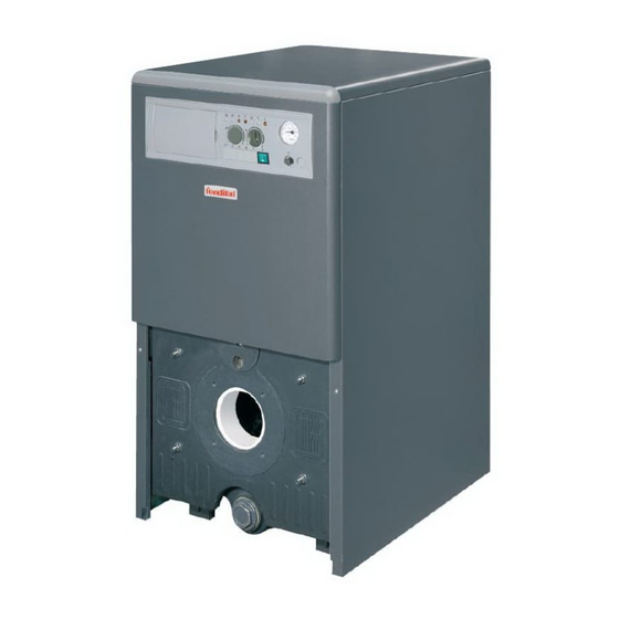
2 Technical features and dimensions 2.1 Technical features This is a floor-standing gas or oil and are fitted with all the safety * Designed for connection to a boiler with a cast iron heat exchan- features required by the applicable remote D.H.W. -
Page 8: Dimensions
2.2 Dimensions 450 mm 225 mm 4 FORI M8 82,5 mm 82,5 mm pic. 2 MODEL Flow A Return B 1" 1/4 1" 1" 1/4 1" 1" 1/4 1" 1" 1/4 1" 1" 1/4 1" 1" 1/4 1"... -
Page 9: Technical Characteristics
2.3 Technical characteristics MODELS ✰✰ ✰✰ ✰✰ ✰✰ ✰✰ ✰✰ EC efficiency rating Max. heat output Heat input 26.6 36.3 47.2 57.9 68.5 79.3 Efficiency at nominal load 91.5 Efficiency at reduced load (30%) 89.7 90.7 90.7 91.1 91.6 91.6 No. -
Page 10: Instructions For The Installer
3 Instructions for the installer 3.1 Installation standards The Manufacturer declines all lia- it to allow removal of the upper bility for damage or injury resulting panel. The boiler must be installed in from failure to follow the above rules. compliance with current laws and standards which are considered an integral part of this han-... -
Page 11: Choosing And Installing The Burner
rectangular chimneys, the inside insulation to protect the burner If the system has any concealed cross section must be 10% greater from the flame (pic. 5). parts, the tightness test must than that of the boiler fitting. WARNING be carried out before covering * The material used must be water- Insulating material adjustment, the pipes. -
Page 12: Hydraulic Connection
Comply with the applicable stan- thermostat valves, radiator stop NOTE: The boiler is equipped dards and laws on boiler instal- valves and the actual configuration with a drain cock, located in lation, which are considered an of the system. the front, which can be used for integral part of this handbook. -
Page 13: Wiring Diagrams
3.5 Wiring diagrams 3.5.1 Boiler layout CH pump feeding Room thermostat connection Water pressure switch connection Electric feeding pic. 8 3.5.2 General layout light blue blue black brown grey green purple yellow yellow/ green pic. 9... -
Page 14: Topographical Layout
3.5.3 Topographical layout (1) PR1 R2-1 R1-3 R1-4 PCB 1 R1-1 R1-2 230Vac 50Hz R6-4 R2-3 R6-3 R2-2 R6-1 R5-2 R6-2 R5-1 R2-4 R4-3 R2-5 R4-2 R3-3 R7-1 R3-2 R7-2 R3-1 R8-1 R8-2 R2-6 R2-7 R3-4 R3-5 R3-6 R4-1 pic. 10 Key to symbols: Minimum temperature thermostat (optional) [on the printed circuit it is indicated with Tm]... -
Page 15: Maintenance
4 Maintenance To ensure that the boiler conti- - condition and tightness of the flue When remounting the front panels, nues to run efficiently, it must be gas pipes check the state of the seals and serviced once a year as specified - condition of all the boiler safety replace them if necessary. - Page 16 Tel. +39 0365 878.31 - Fax + 39 0365 878.576 e mail: info@fondital.it - www.fondital.it The MANUFACTURER reserves the right to implement any necessary and/or useful variation to products, without modifying fundamental characteristics Uff. Pubblicità Fondital IST 03 C 202 - 01 Dicembre 2005 (12/2005)
Need help?
Do you have a question about the ELBA DUAL 23 and is the answer not in the manual?
Questions and answers