
Related Manuals for Magnimage LED-W4000


Summary of Contents for Magnimage LED-W4000
- Page 1 LED-W4000 User manual V2.0 Before using this video processor, please read this manual carefully and keep it for reference in the future. 8k×2K Video Processor...
- Page 2 Statements Without the written permission, any unit or individual could not copy, reproduction or translate the book or part of it. Also could not transmit it in any form or any way (electronic, mechanical, photocopying, record or other way) for any business and profitable purpose. The product specifications and information mentioned in this manual is just for reference, will not give prior notice if there is any update.
-
Page 3: Table Of Contents
Directory Briefs ......................... 1 Trademark credit ......................1 About the software ......................1 Features .......................... 2 Expanded ports ......................3 Safety instructions ......................4 Function Introduction ..................5 Brief ..........................5 The front panel ....................... 6 The front panel ....................... 7 The rear panel ........................ - Page 4 Warranty Description ..................79 Machine warranty ......................79 Non-warranty ....................... 79...
-
Page 5: Briefs
Briefs Thanks for your purchasing our LED video processor. Do hope you can enjoy the experience of the product performance. The design of the LED video processor conforms to international and industry standards. But if with improper operation, there will be a personal injury and property damage. In order to avoid the danger, please obey the relevant instructions when you install and operate the product. -
Page 6: Features
Features 8K x 2K mosaic outputs: W4000 has two output modes: DVI output and HDMI output. The outputs are divided into two groups, each group including 4 DVI and 2 HDMI 2.0 Multiple input ports: DVI-D (4K×1K/60Hz), DP1.1, HDMI1.4, SDI (3G-SDI) ... -
Page 7: Expanded Ports
Expanded ports The LED-W4000 is the basic model. Based on this model, it can be expanded with two 4K/60Hz inputs (DP1.2+HDMI2.0). The expanded models are shown in the following table: Corresponding Available expanded module Description model The 4K/60Hz input module Expand one includes one DP1.2 input... -
Page 8: Safety Instructions
Safety instructions Please use the correct power supply according that the power input voltage for this product range is 100~240V AC, 50/60Hz. When you need connect or pull out any signal or bound guideline. Please confirm that all the power supply cords have been pulled out ahead. ... -
Page 9: Function Introduction
Function Introduction Brief LED-W4000 series is an 8K x 2K video processor which integrates multiple functions such as mosaic, switcher and multi-window display. This processor integrates various professional input ports, single input support maximum 4Kx2K/60Hz or 8Kx1K/60Hz. Because of the high-quality images, pixel display of giant resolution and flexible operation ways, it’s widely used in exhibitions,... - Page 13 Input ports INPUT 1 DVI×1, DP×1, SDI IN×1, SDI LOOP×1, choose one of the three to use at one time INPUT 2 DVI×1, DP×1, HDMI×1, choose one of the three to use at one time INPUT 3 DVI×1, DP×1, HDMI×1, choose one of the three to use at one time INPUT 4 DVI×1, DP×1, HDMI×1, choose one of the three to use...
- Page 14 Control interface RJ45×1 Network cable port, control the machine by LAN USB×1 USB upgrade port, upgrade the machine by a USB flash drive RS232×1 RS232 port GENLOCK IN×1 OUT×1 Genlock port...
-
Page 15: Technical Specifications
Technical specifications Standard input indication Ports Resolution specification 3840×1080/60Hz and other VESA compliant resolutions, supports EDID management Supports 3840×1080/60Hz, 3840×2160/30Hz DP1.1 and EDID management Supports 3840×1080/60Hz and EDID HDMI1.4 management 480i/60Hz, 576i/50Hz, 720p/60HZ, SDI IN×1 SDI LOOP ×1 1080i/50Hz, 1080i/60Hz, 1080P/60Hz ( 3G SDI) Expanded input indication Ports Resolution specification... - Page 16 Output indication Ports Resolution specification (single output port). 1024×768/60Hz 1600×1200/60Hz 1920×1200/60Hz 1280×1024/60Hz 1600×1200/60Hz Rdc 1936×1280/60Hz 1024×768/120Hz 1680×1050/60Hz 2048×1152/60Hz 1280×720/59.94Hz 1920×1080/59.94Hz 1024×1280/60Hz 1280×720/60Hz 1920×1080/60Hz 4×2 1536×1536/60Hz 2048×1920/60Hz 1920×1080/50Hz Customized output resolution (bandwidth optimization). Horizontal resolution up to 2048 pixels. Vertical resolution up to 3840 pixels. 1920×1080/60Hz 1920×1080/120Hz 3840×1080/60Hz...
- Page 17 Machine specification Input power 100-240V AC~50/60Hz 0.6A Operating 0-45℃ temperature Dimensions 482.6×446.3×92.5mm (L × W × H) Net weight 6.7KG Power consumption...
-
Page 18: User Menu
LCD screen according to feedback to the user for operation better, faster and more intuitively. In the following we will introduce the menu system of the LED-W4000 series processor with its buttons, function and the LCD display. -
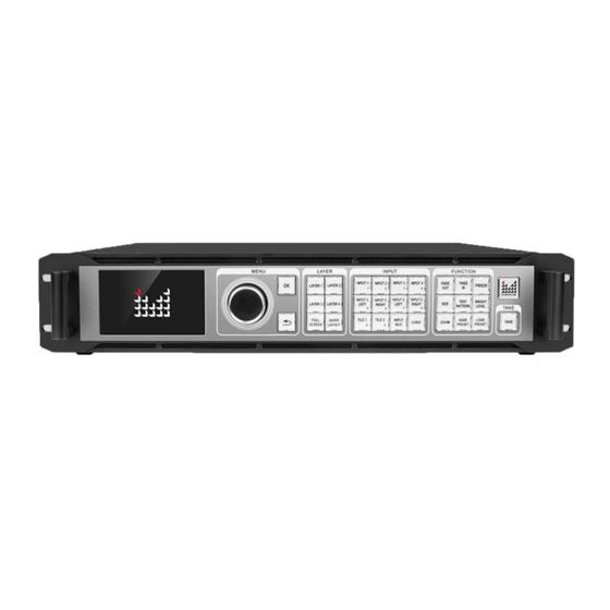
Page 19: How To Use The Buttons
How to use the buttons The front panel buttons are divided into 5 areas: MENU, LAYER, INPUT, FUNCTION and TAKE. MENU area: This area includes 2 buttons and 1 knob that can be pressed: OK, knob. Short press “knob”, its function is the same as the confirmation button (OK);... -
Page 20: Layer Area
the system will not automatically return to the default state, such as user mode shortcut interface, test pattern interface, etc. LAYER area: This area includes 6 buttons, LAYER 1, LAYER 2, LAYER 3, LAYER 4, FULL SCREEN and QUICK LAYOUT. LAYER 1-4 corresponds to the 4 layers of the machine. -
Page 21: Function Area
FUNCTION area: FUNCTION area includes 9 buttons: FADE OUT, FADE IN, FREEZE, SIZE, TEST PATTERN, BRIGHT LEVEL, ZOOM, SAVE PRESET and LOAD PRESET. Buttons Default operation FADE OUT Fade out the selected layer FADE IN Fade in the selected layer FREEZE Freeze current image SIZE... -
Page 22: Default Status Introduction
Default status introduction After power on the LED-W4000 series processor, the boot interface will be displayed on the LCD screen of the front panel during system start up. After the start-up is completed, the main interface of the current machine will be displayed as the default state, as shown below. - Page 23 Input 4 and current input signal resolution, and the Input 4 No Signal right side is the 3 input sources of Input 4. Input 5 and current input signal resolution, the right side is the 2 input sources of Input 5. If this Input 5 4096×2160 expansion board is not added, it will not be displayed here.
-
Page 24: Main Menu Introduction
Main menu introduction The sub-symbols listed in the table below will appear in the main menu. For the specific meanings, please see the following table: Symbol Introduction Press the back button or touch this symbol to return to the main interface or return to the previous menu In the main menu, you can use “OK”, “... - Page 25 confirm the operation or touch click with the "OK" button. Menu button Indicates that the menu has been selected by the knob appears to proceed to the next step. white frame Function menu font Indicates that the function menu is being used. yellow Function menu font...
-
Page 26: Main Menu
Main menu Press “OK” or rotary the knob, you will enter the main menu, and the LCD screen will show as below: PICTURE OUTPUT INPUT LAYERS SAVE/LOAD EDID COMM. MISC TEST PATTERN LANGUAGE Totally 10 items, selected by rotate the knob; The color of selected item is yellow, otherwise is white;... -
Page 27: Picture Setting Menu
Picture setting menu Picture Page: 1/2 Bright LVL Color Management Layer1 Picture Setting Layer2 Picture Setting Layer3 Picture Setting Picture Page: 2/2 Layer4 Picture Setting Reset Picture Setting Cancel Reset Color management: Color Management Color Scenes Disable Disable Gamma Low Gray Suppress Red Enhance Blue Vivid... - Page 28 Layer 1~4 picture setting: Layer1 Picture Setting Brightness Contrast Saturation Color temp Cancel Reset Reset Layer 1~4 color temperature setting: Color Temp Layer 1 Color Temp 6500K Cancel Reset Reset...
- Page 29 Bright LVL Turn on/off the function, level 0~16. Color Low gray, red attenuation, blue enhancement Color Scenes and bright, disabled by default. Management Gamma Turn on/off,Gamma range 0.0~5.0. Brightness:range 0~100, 50 by default. Contrast: range 0~100, 50 by default. Saturation: range 0~100, 50 by default. Layer 1~4 “4000K”,“5000K”,“6500K”,“7500K”,“8200K”...
-
Page 30: Output Setting Menu
Output setting menu Output Mosaic HDMI Switcher Working Mode Mosaic Backup Output Mode DVI Mode DVI Mode HDMI Mode Resolution 1920×1080 60.00Hz Window HDMI Setting DVI mode resolution: Resolution Page: 1/1 1024×768 60Hz 1600×1200 60Hz 1920×1200 60Hz 1280×1024 60Hz 1600×1200 60Hz Rdc 1936×1280 60Hz 1024×768 120Hz 1680×1050 60Hz... - Page 31 Customized Resolution H act 1920 1920 V act 1080 Accept Cancel Advanced Continue <- Customized Resolution(Advanced) 148500000 Hz H act 1920 V act 1080 H tot 2200 V tot 1125 Apply 1920 H sync V sync <- HDMI mode resolution: Resolution 1920×1080 60Hz 4096×1280 60Hz...
- Page 32 Resolution Set Output Resolution To 1920×1080 60Hz Cancel Accept Customized Resolution H act 3840 3840 V act 1080 Accept Cancel < Advanced Continue Customized Resolution(Advanced) 294000000 Hz H act 3840 V act 1080 H tot 4400 V tot 1125 Apply 3840 H sync V sync...
- Page 33 Window(take HDMI output as an example) : Output Panel Config Window Panel Layout Window HDMI1 HDMI2 Reset H Pos Width 3840 V Pos Height 1080 Panel Layout HDMI1 HDMI2 Window H Pos H Pos V Pos V Pos Width 3840 Horizontal Vertical Windows...
- Page 34 HDMI setting: HDMI Setting RGB444 Color Space RGB444 YUV444 8 BIT Deep Color 8 BIT 10 BIT Limited RGB Range Full Full Mosaic mode, HDMI Switcher mode and Backup mode. Mosaic mode: Support maximum 4 layers mosaic output. Take DVI for example, it supports 2 inputs mosaic to 3 outputs, 3 inputs mosaic to 4 outputs, 4 inputs mosaic to 4 outputs.
- Page 35 frequency is 120 Hz, see "output indicators" for details. 2 group of outputs’s resolution is the same. 1. Including output window and output layout two parts. 2. Output layout support automatic layout. Window 3. On switcher working mode, output window’s size is fixed, could not adjust.
- Page 36 About HDR: 1. Adopt HDR 10 format, input/output 10 BIT. 2. Single HDMI output on 4K×2K/60Hz, 8BIT bandwidth range, under 10BIT mode, the load is reduced by about a third, recommend use on 4K×1K/60Hz 10BIT range. 3. Signal only input from input 5 or 6 input port. 4.
-
Page 37: Input Setting Menu
Input setting menu Input Input Signal Information Input MUX Config Tile Keys Config Image Crop Digital Input Color Range Input Information For Layers Input Signal Information: Input Signal Information Page: 1/2 01:Input1-DVI 1920×1080 Total:2200×1125 02:Input1-DP No Signal 03:Input1-SDI No Signal 04:Input2-DVI 1920×1080 Total:2200×1125... - Page 38 Input MUX Config: Configure each group input from which input port. Input MUX Config Input1 Input2 HDMI HDMI Input3 HDMI Input4 HDMI HDMI Input5 HDMI NONE Input6 TILE Keys Config: Combine multiple input signals to a Tile. TILE Keys Config TILE 1 Input 1 + Input2...
- Page 39 Image crop: Image Crop Input 1 Input 2 Input 3 Input 4 Input 5 Input 6 Input 1 1920×1080 Input 1 No Signal Input 1 No Signal Image Crop Input 1 Function OFF Function ON Reset Match To Input H Pos Width H Range 1920...
- Page 40 Input Information For Layers: Input Information For Layers Layer 1 Input1-DVI 1920×1080 60.00Hz Layer 2 Input2-DP No Signal Layer 3 Input3-SDI No Signal Layer 4 Input4-DVI 1920×1080 60.00Hz Display all the input signals’ information of each input Input Signal port, the content sequence — signal type — input Information resolution or no signal —...
- Page 41 under cropping. Function off Turn off the image crop function. Function on Turn on the image crop function reset Reset the parameters of image crop. Match input Match the image parameters between signal input signal and below image crop. Alter the horizontal H position position of image crop.
- Page 42 About Tile key configuration: 1. On mosaic mode and backup mode,support 4*2K×1K,2*2K×1K or 2*2K×2K range input signal combine to a Tile. 2. On switcher mode,support 2*2K×1K range input signal combine to a Tile. 3. Only same resolution signals could be combined to a Tile. 4.
-
Page 43: Layers Setting Menu
Layers setting menu Layers Setting menu: It has a slightly differences on mosaic mode, switcher mode, and backup mode, specific introduce as below, On mosaic mode: support layer quick setting. LAYERS(Mosaic) Layer Quick Setting Layer Configuration Zoom Duration LVL 2 Layer Quick Setting (Auto layout): Layer Quick Setting Layer 1... - Page 44 Layer configuration:manually open/close layer, modify layer’s size, position, rotation. Layer Configuration Layer 1 Layer 2 Layer 3 Layer 4 Layer Property H Pos Width 3840 V Pos Height 1080 Layer Property Layer 1 Chroma Keyr Alpha Chroma Keyer Layer 1 Only Show Colors Defined Below R Low Function OFF G Low...
- Page 45 Chroma Keyer Layer 1 Quickset Pure Red Pure Green Pure Blue Red Screen Matting Blue Screen Matting Green Screen Matting Red On Black Green On Black Blue On Black Red On White Green On White Blue On White Black On White White On Black Zoom: layer zoom function.
- Page 46 On HDMI switcher mode: could not support rotation, chroma key and layer transparency adjust. LAYERS(HDMI SW) Layer configuration Zoom Duration Layer Configuration Layer 1 Layer 2 Layer 3 H Pos Width 3840 V Pos Hight 1080 Zoom Layer 1 Layer 2 Layer 3 Function OFF Function ON...
- Page 47 Backup mode: support automatic and manually backup, multi-machine backup synchronously, main and aux output switching support fade in/out. LAYERS(Backup) Layer Configuration Zoom Duration LVL 3 Auto Backup Disable Disable Enable TAKE Together Disable Layer configuration-select input: use to main layer and backup layer select input signals.
- Page 48 Mosaic mode/HDMI Switcher mode/Backup Mosaic mode three types working mode should switch mode/Switcher on: output setting-working mode, different mode/Backup mode working mode has a slight different menu on “Layers Setting”. Operating open or close any layer1 to 4 and adjust the layer’s size, position, rotation directions.
- Page 49 Layer zooming Adjust zooming the layer’s size and paramet datum. Switcher chooses the duration of layers in splicing Duration mode, default LVL2, adjustable LVL1 and Cut (fade-in and fade-out time of single layer. Layer Select open or close any layer1~3,adjust the layer configur size and position.
- Page 50 vertical datum. Layer zooming Adjust layer zooming size, parameters position, datum. Select the main/backup input duration on the Duration backup mode, default Cut, could choose LVL 1,LVL 2,LVL 3. Auto Function is enabled/disabled. Backup The function is enabled/disabled, and mutually backup is exclusive with automatic backup.
-
Page 51: Save & Load
Save & Load Save or Load Save Preset Load Preset Delete Preset Cancel Clear All Preset Accept Preset Source Program Program Preview Save Preset Saving Finished Mosaic Preset 1 Will Be Overwritten Cancel Continue Load Preset Loading Mosaic... - Page 52 Delete Preset Mosaic Save Preset Mosaic Shows which currently saved preset is saved in mode which operating mode in this processor. 1~20 It can save 20 presets. Selecting a saved preset will prompt whether to overwrite the preset. Mosaic Shows which currently loaded preset is loaded mode in which operating mode of this processor.
-
Page 53: Edid Setting
EDID setting EDID Input 1 Input 2 Input 3 Input 4 Input 5 Input 6 Input 1 1920×1080 60.00Hz Input 1 1920×1080 60.00Hz Input 1 Not Support EDID EDID DVI Input 1 1920 H Active 1920 V Active 1080 V Fraq Reset Accept Advanced... - Page 54 our technicians. If you accidentally modify the menu, click the reset button. H Blank Modify EDID’s horizontal blank. V Blank Modify EDID’s vertical blank. Note 1: When performing EDID configuration, the computer display mode needs to be set to the expanded mode. Note 2: After setting the EDID, due to different computers and different graphics cards, it may need to restart the computer or plug in the signal cable.
-
Page 55: Comm. Setting Menu
COMM. setting menu Communication IP Address 192.168. 1.222 Edit 192.168. 1. 1 Edit Gateway E2-B2-E0-EC-45-17 Reset <- Apply By modifying the IP address and gateway of the Communication processor, it is convenient for the computer to setting connect to the processor through the network using the host computer. -
Page 56: Misc. Menu
MISC. menu Misc Page: 1/2 Status Info Mosaic Logo HDMI Switcher Backup Working Mode Mosaic FreeRun Sync Lock Setting FreeRun Lock To LAYER1 Genlock Screen Touch Enable Enable Disable Misc Page: 2/2 Date & Time Schedule & Task Factory Reset Status Info Status Info Firmware Version... - Page 57 Firmware Version MAGNIMAGE LED-W4000 Main Board: B0003 A0004 Mar 5 2019 14 : 43 : 25 UI Board : B0003 A0004 Mar 5 2019 18 : 21 : 25 Electric Info 1. voltage, (STD: 1100 mv), 1336 mv. 2. voltage, (STD: 1500 mv), 1484 mv.
- Page 58 Logo LOGO Saving 3840×1080 For Mosaic Load Save New Logo Layer Layer 2 Start Delete Delete Cancel 2. HDMI switcher mode Logo Not Saved Load Save New Logo Program Channel Program Preview Layer 3 Layer Layer 1 Layer 2 Start Layer 1 Delete Delete...
- Page 59 3. Backup mode Logo Logo Saving 3840×1080 For Backup Load Save New Logo Start Delete Delete Cancel Date & Time: Date & Time Date 2018/02/24 Edit 20:41:38 Edit Time Saturday Reset <- Apply Schedule & Task: Schedule & Task 2018/02/24 20:46:09 Task Config Cancel...
- Page 60 Task Config: Task Select Mosaic Task Config Date 2019/01/01 --:--:-- Time Skip Frequeny Select Preset Cancel Apply Task Config Date 2019/01/01 --:--:-- Time Skip Frequeny Select Preset <-...
- Page 61 Task Config Date 2019/01/01 Skip --:--:-- Time Only Once Skip Frequeny Every day Select Preset Period Cancel Apply Task Config Date 2019/01/01 Time --:--:-- Select Preset Frequeny Skip Select Preset 10 11 12 Cancel Apply 13 14 15 16 17 18 19 20 Factory Reset: Factory Reset Factory Reseting…...
- Page 62 Misc. setting Set the functions of this unit. Firmwar Displays the machine name and firmware e Version version. Status Info Electrical Displays the electrical status of each part of Info the unit. Save and load the Logo menu, save the output image on this processor as Logo and load.
- Page 63 Date display Displays the current date of the unit. Display 20 tasks in the current working mode of the machine, Select task click the number 1~20 task that needs to be operated to enter the task setting menu. Select the date on which the Date current task performs the action.
- Page 64 Note 1: The test chart will be rebuilt after each factory reset, just click to continue. Note 2: Save Logo is the logo save in the current working mode of the processor, so please confirm whether the current working mode of the machine is correct before saving the logo.
-
Page 65: Test Pattern
TEST PATTERN Test Pattern Test Pattern Test Pattern For LCD Screen Pixel Grab Warning Pattern Generator Database Needs To Be Rebuilt Cancel Continue Test Pattern For LCD Screen: Touch Here To Quit To Select Patterns To Show The Hint To Hide The Hint To Quit Current Menu Touch Here To Next Pattern Touch Here To Prev Pattern... - Page 66 Pixel Grab: Window DVI1 DVI2 DVI3 DVI4 Pixel Color H Pos V Pos Window HDMI1 HDMI2 Pixel Color H Pos V Pos Capture selected pixel colors: Window DVI1 DVI2 DVI3 DVI4 Pixel Color H Pos V Pos...
- Page 67 Output test image, easy to test all output ports and LED screen of this unit without input signal, range 0~111. When after the Test processor factory Pattern Figure database reset, the submenu card needs to will pop up. Click TEST generator PATTERN Continue to use the...
-
Page 68: Language Submenu
Language submenu Language/语言 English 简体中文 繁體中文 Set the display language of the menu system to English English. 简体中文 Set the display language of the menu system to simplified Chinese. Simplified Chinese 繁體中文 Set the display language of the menu system to traditional Chinese. -
Page 69: Quick Use Instructions
Quick Use Instructions The rear panel introduction 3. Groupsoutput 2. Expandedport 4. controlandupgradeport 1. Standardinput:12input Input area port: Standard input port (red line part): 12 channels, divided into 4 groups, each group of 3 signals, choose one of three to use each time;... - Page 70 EDID. DP supports 8K×1K/60Hz; single module includes DP×1, HDMI×1 (including 1 LOOP), Single input boards, choose one of two port to use. Output area port: Output port: 12 channel, divide into 2 groups First group: HDMI1A/1B、DVI1A/1B、DVI2A/2B Second group: HDMI1A/1B、DVI1A/1B、DVI2A/2B DVI, HDMI alternative one of two to use each time. Control area: Interface: RJ45 network ×...
-
Page 71: The Front Panel Introduction
The front panel introduction Touch screen Knob/ok button/return Take boutton on switcher mode Common function shortcuts layer selected and open Selected input signal area Touch screen: To prevent parameter confusion caused by accidental touch, the outermost standby interface is unavailable on. - Page 72 inputs are 4K×2K@60Hz, the signal input It is divided into left and right processing, corresponding to Input 5 Left/Input 5 Right/Input 6 Left/Input 6 Right; (Input 1-4 does not divide left and right). TILE: Combination signal selection button, up to two signal combination keys, corresponding to Tile 1 and Tile 2.
-
Page 73: Input Signal Information, Tile Function Introduction
Input signal information, TILE function introduction 1. Input Signal Information Set one of the signals in each group of inputs to be used as input (three inputs per group, choose three for one to use). Select the "Input Signal Information" menu: PICTURE OUTPUT INPUT... - Page 74 2. TILE function introduction Multiple input sources can be spliced into one unit at the input port as a combined signal source. For example, the graphics card 3 DVI horizontal splicing output to the W4000, through Tile function, it can make a 3 DVI signal into a tile, which is convenient for unified calling and zooming.
-
Page 75: Working Mode Introduction
Working mode introduction This processor has three working modes: Mosaic mode, Switcher (HDMI) mode, and Backup mode. Two output modes: DVI and HDMI, only HDMI output is supported on Switcher mode. Mosaic mode function 1. Enter “Output setting”in the main menu, select the Mosaic mode, use DVI or HDMI output, and output resolution of single output port. - Page 76 Window HDMI1 HDMI2 Reset H Pos Width 3840 V Pos Height 1080 The output port can be arranged horizontally, vertically, and 4 identical squares (on DVI output). Layer Configuration Layer 1 Layer 2 Layer 3 Layer 4 Layer Property H Pos Width 3840 V Pos...
- Page 77 (horizontal, vertical, or 4 identical squares layout). The LED-W4000 output each layer is independent. By setting the size of the output window and the layout of the output to matches the actual load. Through the “Layer quick setting”,multiple inputs can be quickly spliced and spread to the entire output, thus realizing the processor “2 input, 3 output...
-
Page 78: Switcher Function
Switcher function 1. Switcher mode setting: Select "HDMISwitcher" working mode (Switcher mode, only HDMI has output), on the main menu "Function Options". HDMI 1 A / B is the main output, HDMI 2 A / B is preview (with preview indicate). Output Mosaic HDMI Switcher... - Page 79 in the left half of the output, LAYER 3 only supports the right half of the output. C. In 4K×2K output resolution, support 1 layer to 1 layer preview switch. D. In the switch mode, the output window size cannot be adjusted. 3.
- Page 80 make preset load and switch operations. D. Saved presets, the number key is highlighted. 4. Duration, there are "CUT" and "LEVEL1-3" optional. LAYERS(HDMI SW) Layer configuration Zoom Duration...
-
Page 81: Backup Mode Function Introduction
Backup mode function introduction 1. Enter “OUTPUT Setting” in the main menu, select Backup mode, use DVI or HDMI output, and output resolution of single output port. Output Mosaic HDMI Switcher Working Mode Backup Backup Output Mode HDMI Mode DVI Mode HDMI Mode Resolution 3840×2160 60.00Hz... - Page 82 Layer Configuration Input Select Input Input1 LOGO H Pos Width 7680 V Pos Height 1080 Note: 1. On Backup mode, only layer1 and layer 2 can be used, and the layer size/position is always the same. 2. Pay attention to the processor LCD panel prompt, the default layer1 is the main display, layer2 is the backup, when TAKE is switched, layer2 is the main display, layer1 is the backup, the main display layer is always at the top, backup is at the bottom.
- Page 83 Warranty Description Machine warranty 24 months from the date of purchase of the user’s invoice. If the user purchase invoice is lost, the 60 days after the production date will be the warranty start date for the product. Non-warranty ...
Need help?
Do you have a question about the LED-W4000 and is the answer not in the manual?
Questions and answers