
Related Manuals for Magnimage LED-780HD


Summary of Contents for Magnimage LED-780HD
- Page 1 4K×2K Video Processor User Manual V1.1 △ Before using this LED Video processor,please read this manual carefully and preserved for reference in the future. LED-780H...
-
Page 2: Statements
Statements Without the written permission, any unit or individual could not copy, reproduction or translate the book or part of it. Also could not transmit it in any form or any way(electronic, mechanical, photocopying, record or other way) for any business and profitable purpose. The product specifications and information mentioned in this manual is just for reference, will not give prior notice if there is any updated. -
Page 3: Table Of Contents
Directory Statements ..............................1 Directory ................................ 2 Briefs ................................4 Trademark Credit ................................4 About Software ................................4 Features ................................... 5 Including Accessories ..............................6 Extended Port .................................. 7 Safety Instructions ................................9 Function Introduction ..........................10 Brief....................................10 About the front ................................11 About the back ................................ - Page 4 Switcher Mode ..............................52 PIP ..................................53 Image Crop ................................. 54 LOGO Setting ..............................55 EDID Setting ............................... 56 VGA Adjustment ..............................57 Misc Setting ................................ 58 Time & Task ................................ 61 Input Source Information ............................ 62 Synchronous Mode.............................. 63 Preset and Template.............................
-
Page 5: Briefs
Briefs Thanks for your purchasing our LED Video processor. Do hope you can enjoy the experience of the product performance. The design of the LED video processor conforms to international and industry standards. But if with improper operation, there will be a personal injury and property damage. In order to avoid the dangerous, please obey the relevant instructions when you install and operate the product. -
Page 6: Features
Features 4 ScreensSplicing in 1 Processor: 8 DVI output ports are divided into 4 groups for horizontal splicing, vertical splicing, same size splicing, and different size splicing. A single unit up-loads 8,000,000 pixels and accepts splicing for 4 screens. 4 windows output:On non-splicingmode, each output is capable of ... -
Page 7: Including Accessories
Including Accessories Using manual Power line DVI signal cable USB cable 232 serial line Big port DP Mini DP to Big Certification of cable quality... -
Page 8: Extended Port
IP echo output and one DVI monitor output), extended models as follows: Port Model Explanation 1 DVI module includes 1 DVI input Extended one DVI LED-780HD and I DVI loop port 1 DVI module includes 1 DVI input Extended two DVI LED-780HD2... - Page 9 Port Model Explanation 1 GENLOCK module includes 1 Extended LED-780HG synchronous input GENLOCK port Output synchronous output port 1 monitor module includes 1 IP echo Extended LED-783H output and 1 DVI monitor output Monitorport...
-
Page 10: Safety Instructions
Safety Instructions Please use the correct power supply according that the power input voltage for this product range is 100~240V AC, 50/60Hz. When you need connect or pull out any signal or bound guideline. Please confirm that all the power supply cords have been pulled out ahead. ... -
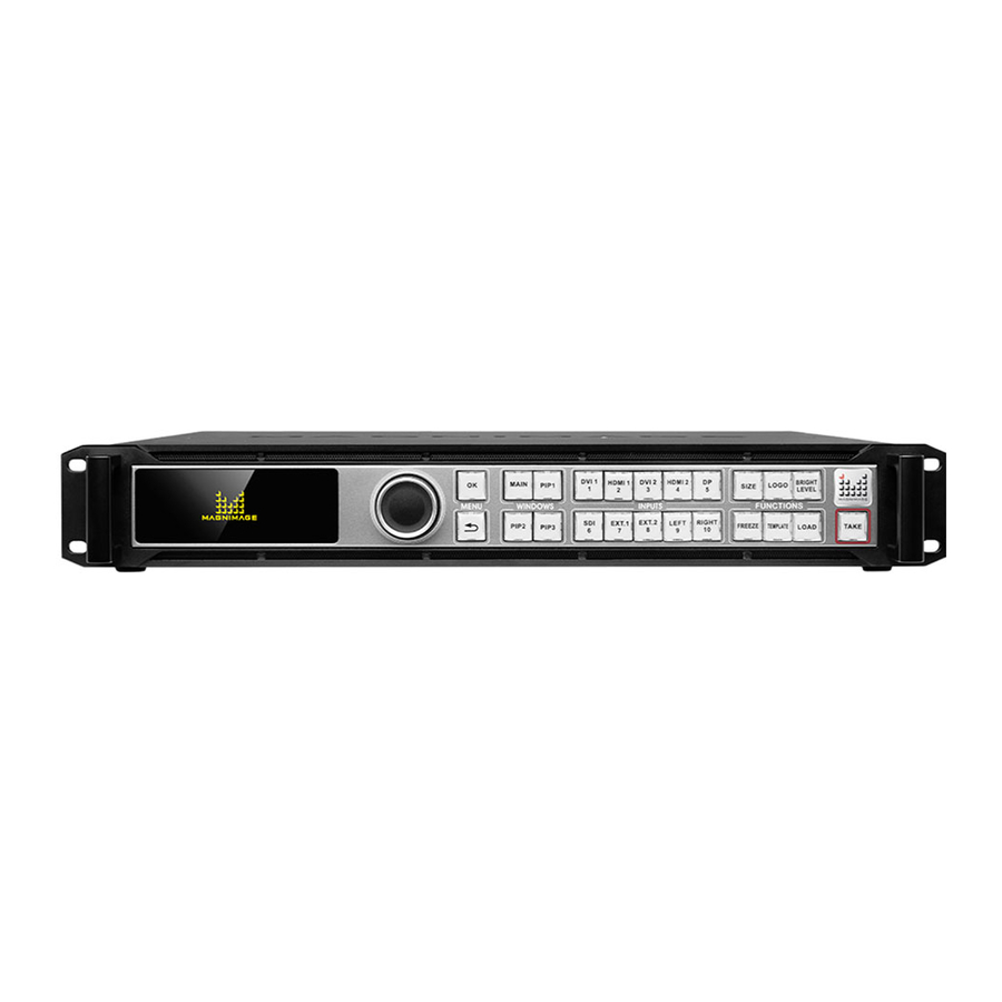
Page 11: Function Introduction
Function Introduction Brief LED-780H,a superior approach to better visual performance for LED walls. It is a 4k*2k/60Hz capable video processor for 4 screens splicing. With EDID and user-defined output management, it delivers high quality pixel-to-pixel display via its user-friendly controls. It is an ideal choice for multi-media hall, multi-purpose room,theater,studio and showroom. -
Page 15: Technical Specifications
Input Port DVI1-DVI2 2 DVI input ports HDMI1-HDMI2 2 HDMI input ports 1 DP input port,3840×1080/60Hz or 3840×2160/30Hz 1SDI input port, with 1 SDI loop EXT.1 Extended port 1 EXT.2 Extended port 2 Output Port DVI1A-DVI1B Output group 1,the DVI under is a backup port DVI2A-DVI2B Output group 2,the DVI under is a backup port DVI3A-DVI3B... - Page 16 Output Indication Port Quantity Resolution(each DVI output) 1024×768/60Hz 1280×720/60Hz 1280×1024/60Hz 1440×900/60Hz 1024×768/120Hz 1600×1200/60Hz 2048×1152/60Hz 1680×1050/60Hz 1600×1200/60Hz-reduced 1920×1080/50Hz 8 ports, 1920×1080/60Hz 1920×1200/60Hz 2176×1168/60Hz 4 groups. 1024×1280/60Hz 1936×1280/60Hz 1536×1536/60Hz Customized output resolution ( Bandwidth optimized) : The width resolution is up to 3840 The height resolution is up to 2160 DP Loop In accordance with DP input...
-
Page 17: Using Menu
Using Menu Using the menu system is helpful to finish all your settings to this product. LED-780Hadopts a full color LCD screen to display the information. If there is no any operating or the operating is timeout, the LCD screen will be in default state. -
Page 18: Windows
In the browse mode, rotate the knob anticlockwise, the menu will go up or go left. Rotate the knob clockwise, the menu will go down or go right. Rotate and press the knob(or press “OK”button),the menu option will be selected. After that, rotate the knob anticlockwise, the value of the selected option will decrease, while the value will be increased when rotating the knob clockwise. -
Page 19: Function
FUNCTION: There are 6 buttons in this area:SIZE、LOGO、BRIGHT LEVEL、FREEZE、 TEMPLATE、LOAD. Button Default operating when pressing SIZE Enter the size setting menu LOGO Turn on or turn of the logo BRIGHT Enter the brightness level menu LEVEL FREEZE Freeze the current image TEMPLATE Enter the template window. -
Page 20: Main Menu Introduction
Main Menu Introduction Below symbols will appear in the main menu,their specific meaning are shown as below table: Symbols meaning press“OK” to enter the submenu Through“OK”、“ ”and the knob ,setting the parameters or do some adjustment,below are the detailed introduction: Purpose Operation Open... -
Page 21: Main Menu
Main Menu: In the default state, press "knob" or "OK" to enter the main MENU state, the LCD screen will show the details as below: Picture Setting Output Setting Mosaic Setting Switcher Mode PIP Settings Image Crop EDID Settings VGA Adjustment Communication Misc Sync Lock Setting... -
Page 22: Image Setting Submenu
Image setting submenu Standard [MAIN]Input: Picture Mode DVI1 Disabled Bright Level Brightness Gamma Correction Contrast Saturation [MAIN]Picture Settings [PIP1]Picture Settings [PIP2]Picture Settings Sharpness [PIP3]Picture Settings Color Temperature Reset Picture Settings Reset Settings Divided into“standard”、“low-light 1”、 “low-light 2” 、 “low-light 3” 、 Image setting “video”... -
Page 23: Output Setting Sub Menu
Output Setting sub menu Select Output Resolution Output Resolution [MAIN]Output Window 15 1024×1280 60Hz [PIP1]Output Window 16 1536×1536 60Hz [PIP2]Output Window 17 Customized Resolution [PIP3]Output Window 17th:Customized Resolution 1920 H Active V Active 1080 60Hz Apply ON 1920×1080 MAIN Width 1920 Height 1080... - Page 24 Minimum 0,the biggest can be set to the differentials H Position between “the width of the current output resolution” and“H Window”.. Minimum 0,the biggest can be set to the differentials V Position between “ the height current output resolution”and“V Window” Rotation Include -90°、90°、horizontal、vertical、180°、-90°+horizontal、90°...
-
Page 25: Mosaic Sub Menu
Mosaic sub menu Mosaic Setting Mosaic Setting 4 Panels Manual Arrangement MAIN 1 Panel 2 Panels PIP2 Auto Arrangement PIP3 3 Panels 4 Panels Manual Arrangement Mosaic Setting MAIN MAIN Mosaic Setting H Total 1920 V Total 1080 PIP1 Width Height PIP2 H Start... - Page 26 by the current video processor. The LED screen top-left corner is viewed as the original point (vertical starting point 0). Auto arrangement Caculate the mosaic parameter autolly to complete the mosaic. LED-780H series video processor’s mosaic setting ,totally 5 mode: Off:close mosaic function,at this state, all the output ports output the same picture.
-
Page 27: Switcher Mode Sub Menu
Switcher mode sub menu To Use Switcher Modes Mosaic Function Must be OFF Proceed to use switcher mode Cancel And Exit Switcher Mode Switcher Mode Fade Duration 0.5s PIP1 MAIN PIP2 1 Panel Multi Switch PIP3 2 Panels DVI1-4 Switcher mode include“OFF“, “single screen“and“dual screen“... -
Page 28: Pip Setting
PIP Setting PIP1 PIP Settings Input DVI2 PIP1 PIP2 Alpha Hold PIPn Key To Toggle ON/OFF PIP3 In pip setting sub menu, do such adjustments :open pip or turn off pip, and select input signal ,transparency adjustment(0-64) To change the pip size,use the“SIZE” key in the front panel . -
Page 29: Image Crop Setting Sub Menu
Image crop setting sub menu Image Crop MAIN MAIN DVI2 PIP1 Image Crop PIP2 Parameters (0,0)1920×1080 Reset Image Crop Settings PIP3 H Start V Start Width 1920 Height 1080 select “ MAIN” 、 “PIP1” 、 “PIP2” 、 “PIP3” cropping parameters; each signal Image crop can be cropped in different picture at the same time. -
Page 30: Edid Setting
EDID setting EDID Select DVI1 H Active 1280 V Active 60Hz Apply EDID select select one input signal EDID H Active Horizontal width V Active Vertical height Refresh rate After setting EDID, different PC, different video card, need restart PC or pull ot signal line, choose appropriate resolution in PC resolution output menu. -
Page 31: Communication Setting
Communication Setting 192.168.1.110 Network Setings RS232 Baudrate 115200 Apply Reset MAC:E2-CB-16-E0-73-6F Network settings Select IP address of this PC RS232 Baudrate Fixed value 115200 Misc Setting Display in two pages LOGO Settings Chroma Keyer Settings Templates And Presets Time/Task Managment Loop Out Settings DVI1 Pattern/Caption... - Page 32 PIP function Modify normal state, used as activity picture. Modify logo state, used as LoGO function;PIP3 and LOGO occupy same output, can choose one of both. Save LOGO Modify store file, maximum 4 Save PIP3 picture as LOGO, adjust size and position in save interface Horizontal area: maximum value is the width of PIP3 Vertical area: maximum value is the height of PIP3 H start: maximum value is the difference of PIP3 height and LOGO width...
- Page 33 Chroma keyer settings High Reset Chroma Keyer Red On Black Keyer Mode Color Range Green Chroma Keyer On PIP3!!! Blue Chroma On or off chroma keyer function keyer User、 white on black、 white on black 2、 black on white、 black on white 2、 green keyer on black、green on black 2、green on white、green on white 2、red on black、...
- Page 34 Delete Enter delete interface, delete presets via pressing No. button Time & Task management Date And Time Date 2017/3/16 Schedule Time 20:10:35 Schedule Run/Stop Stop Schedule List Date:2017/3/16 Time:--:--:-- Preset Index Loaded Not Used Task Operation [OK]To Edit Schedule date Set date Data and time time...
-
Page 35: Synchronization Lock Setting
Pattern/caption Test Pattern Test Pattern Pixel Grab Pattern Index Caption Caption Caption Show Freeze Scroll Speed Caption #1 Caption Select Left Scroll Direction Caption config Background Mode Transparent Caption Function Reset Color Config Range 0-110 ; 0 represent no test pattern display,1~72 test pattern Test pattern No.。... -
Page 36: Language/语言 Submenu
Include “ synchronize to Main ”、“ synchronize to Genlock ”、 Synchronization “synchronize to input DVI1” 、 “synchronize to DVI2” 、 “synchronize Lock Mode synchronize to HDMI1” 、 “synchronize to HDMI2” 、 “synchronize to DP” 、 “free-rolling”. Synchronization Include“automatic” 、 “Mode 1“、 ”Mode 2” 。 Mode 1、... -
Page 37: Mosaic Function
Mosaic function 5 basic setting steps of LED-780H video processor: 1. Mosaic Setting: Select a mode of mosaic; 2. Select corresponding input signal for each layer; 3. Adjust output resolution; 4. Adjust the window size of each output; 5. Adjust mosaic parameters of each layer. Single input scaled-up mosaic For Example: P3.91 LED Screen, 15m x 5.5m, total resolution is 3840 x 1408, divided into 3 load area, like below:... - Page 38 Output layer MAIN PIP 1 PIP 2 parameters H Total 3840 3840 3840 V Total 1408 1408 1408 Width 1280 1280 1280 Height 1408 1408 1408 H start 1280 2560 V start There are 6 parameters in manual mosaic, to realize equal/not equal, horizontal/vertical mosaic.
-
Page 39: Multiple Input Scaled-Up Mosaic
Multiple input scaled-up mosaic Considering display definition, sometimes it requires video server output 2 DVI or 4K DP signal to video processor to archive clear images, meantime, there is a little different from single input scaled-up mosaic. 2 DVI input horizontal scaled-up mosaic Single machine 4-panel mosaic Video server output 2 DVI signal (1920x1080) to LED-780H synchronously, LED-780H output for 4 panels mosaic;... - Page 40 Output layer MAIN PIP 1 PIP 2 PIP 3 parameters H Total 2560 2560 2560 2560 V Total 1152 1152 1152 1152 Width 1280 1280 1280 1280 Height 1152 1152 1152 1152 H start 1280 1280 V start NOTE: 1. As 2 DVI input signal are mosaic and output by front-end video server, so 2 of the output port of the processor mosaic 1 of the input signal, and another 2 output port mosaic another input signal;...
- Page 41 Single machine 3-panle mosaic Video server output 2 DVI signal (1920x1080) to LED-780H synchronously, LED-780H output for 3 panels mosaic; For example: P4.81 LED screen, 23m x 5m, total resolution is 4784 x 1040; divided into 4 load areas, as below: 1872 1872 1040...
- Page 42 Applicable to DP L+R Input Press [OK] Confirm 2. Select DVI1 for MAIN and PIP1, DVI2 for PIP2 and PIP3; PIP 1 PIP 2 PIP 3 MAIN 3. Output setting---output resolution---17th customize resolution as 1872× 1040@60Hz; 4. Output setting---Output window; Output layer MAIN...
-
Page 43: Note Of Dp
V Total 1040 1040 1040 1040 Width 1872 1352 1040 Height 1040 1040 1040 1040 H start 1872 1352 V start NOTE of DP Regarding LED-780H DP input, in 2K resolution situation, press DP button to select current DP input; in 4K resolution situation, DP input will be split into DP-L and DP-R automatically, L presents left part of 4K input and R presents right part;... -
Page 44: Controlling Software Operation Introduction
Controlling Software operation introduction LED-780H controlling software(called the software) is professional software aimed at video processor. The interface is Intuitive concise, easily handle, and almost all the function of controller can be realized by the software. Working with “output preview board”, we can check the real-time input signal in the interface of the software. -
Page 45: Installing Processing
Installing processing Double-click program start install, click "Next" to go on. Select program installation location, and setup the program user. Confirm all the setting, and click “Next” to go on. Ask for uses-permission, please select “Yes”. When they finish, please click the “Close”. -
Page 46: Unload The Software
Unload the software Double-click the installer, start the uninstall with the software, click "Next" to go on. Finish and click “Close”. ... -
Page 47: Open The Software
Open the software After opened the software, you will see 4 parts in your PC. 1、Functional area 2、Signal selection area 3、Operation area (black area) 4、Area templates and presets. -
Page 48: Connection Setting
Connection setting Connection Settings: network connection and COM connection 1, Network connection a> Destination IP:IP Processor b>Local IP:Computer IP address Destination IP and the local IP in the same network, click "search" machines, will open a list, select "connect". If succeed will be reminded, the diagram below: Double-click the icon, select the machine... - Page 49 2, COM connection Connect via RS232 serial port, Baud rate is 115200...
-
Page 50: Image Setting
Image setting Picture mode Standard,Low light,Monochrome,Video,Graphic, User Layer Choose MAIN/ PIP1/2/3, change what you want Temperature Change the color temperature, RED/ GREEN/ BLUE. Open Picture Mode to User at first, and that you can change Layer and Temperature. -
Page 51: Outputsetting
OutputSetting Output Choose a fixed output resolution and customize output resolution Resolution Output window Select pictures, change the size and position of the corresponding picture Rotation rotation angle of the output image... -
Page 52: Mosaic Setting
Mosaic Setting Mosaic mode Mode: Panel*1, Panel*2, Panel*3, Panel*4. Corresponding is Single output, two screen, three screen, four screen mosaic. And turn on/off the Mosaic mode. Automatic Choose the splicing position, such as horizontal, vertical, Arrangement grid-shaped. Manual Change each splicing output resolution, to realize image stitching Arrangement... -
Page 53: Switcher Mode
Switcher Mode Switcher Mode Mode: Panel*1, Panel*2 Panel*1: One is preview, and one is program. Panel*2: Two is preview, and two is program. Fade duration: Change fade time Multi-Machine One computer control multiple machines , switch at the same Mode: time... -
Page 54: Pip
PIP1 PIP 1 turn on/off,select input signal and change the alpha. PIP2 PIP 2 turn on/off,select input signal and change the alpha. PIP3 PIP 3 turn on/off,select input signal and change the alpha. T-BAR Fade in/out on this screen... -
Page 55: Image Crop
Image Crop Yellow area:the size of the input signal Black frame:the size and position of the video crop "Video Crop" is realized by cropping the input signal, transferring to the LED display according to the size of output port and then presenting the image. Thus the size and position of the video crop is based on the set up of the input signal. -
Page 56: Logo Setting
LOGO Setting PIP3 Mode LOGO is only applied in the PIP-3, please enter the logo mode in PIP3 for the need of LOGO Position Adjust the size and position of the LOGO File LOGO file loading and clear LOGO Setting LOGO top or bottom LOGO Border Used in the grab or load time,... -
Page 57: Edid Setting
EDID Setting Select an input source,and then change the width, height, frame rate, adjust to the corresponding input resolution;Then click Apply, Front-end settings will automatically recommend this resolution output to the processor,If it does not appear,Please reboot the front end setting (for example,restart the computer) or re-insert the input signal line... -
Page 58: Vga Adjustment
VGA Adjustment Display In the case of position offset, apply VGA correction, generally Adjustment choose“ Auto Adjustment” ADC Adjustment Adjust the color of the VGA signal DDC Setting DDC setting is only for on/off switch, please contact our technician for the other two settings. -
Page 59: Misc Setting
Misc Setting Language/语言 Select English or Chinese interface File Location Save and load project files Loopout Setting DP loop port allow options of loopout of any signals System System software version, firmware information Information Factory Reset To reset the machine to the Factory setting... - Page 60 Color Key It is efficient only PIP-3 You can choose shortcut mode or user-defined mode. For Color Key Mode example, white-on-black writing,which means it will remove the black bottom automatically, only leave white text. Then, it will on the effect of words superposition.
- Page 61 Pattern/Caption Test Pattern The processor outputs the local test signal Read Pixel By adjusting the position, read the current pixel color Enter the advanced setting of subtitle, Just edit subtitle info Subtitle Setting in the software, including subtitle content, font size, color, location; Scroll speed, direction, background color...
-
Page 62: Time & Task
Time & Task Time Time on the machine can be synchronized with time on computer Schedule The Switch of Schedule, a total of 10 time tasks, can be edited separately... -
Page 63: Input Source Information
Task Editor Select a trigger time, and then select a trigger cycle, finally select the trigger action, Such as call the default time at 12:00 every day 2, Time is set to 12:00,Task Action Select "Daily" Then click Apply For example, apply preset 2 at 12:00 everyday, set the trigger time to be 12:00;trigger action to be “... -
Page 64: Synchronous Mode
Synchronous Mode Synchronous The machine provides multiple synchronous modes, or is Mode directly synchronized to an input source. Generally use the default settings. Preset and Template Below the software interface, preset and template options are available 1、Preset Save After setting up all the items, parameters can be saved,10 items in total Load Load the saved parameters... -
Page 65: Warranty
Warranty The whole unit warranty One year (from the buying date); If the invoice is lost, the 60 days after the production date will be the warranty start date for the product. The warrnty provisions The machine soaking and collisions produced besmirch or surface scratches and other abnormal using causes of malfunction or damage;...
Need help?
Do you have a question about the LED-780HD and is the answer not in the manual?
Questions and answers