Table of Contents
Advertisement
Advertisement
Table of Contents

Related Manuals for Genvex COMBI 185 BP


Summary of Contents for Genvex COMBI 185 BP
- Page 1 INSTALLATION INSTRUCTIONS COMBI 185 BP...
-
Page 2: Table Of Contents
TABLE OF CONTENTS About the Product ................................3 Transportation and Storage..........................3 Directions/Safety Instructions ..........................3 Product Description ..............................4 Installation .....................................5 Setup .....................................5 Connecting to a Water Main ..........................5 Connecting to Condensate Drain ........................5 Connecting Ducts ..............................6 Ducting System ................................ .7 Insulation of Ducts in Cold Lofts .........................7 Insulation of Ducts in Heated Spaces .......................8 Electric Water Heater/Sensor/Anode .......................8... -
Page 3: About The Product
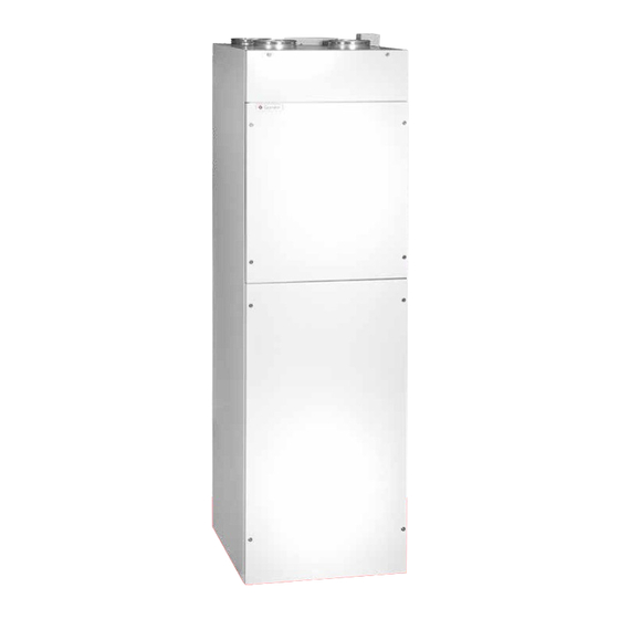
ABOUT THE PRODUCT Transportation and Storage Product Description As a rule, the unit should be stored packaged in an upright position and without water. Transported with care and over The Combi 185 is a combined ventilation unit and domes- short distances, the unit may be tilted to up to 45 °C. tic water heat pump which can be used for: •... - Page 4 Output Defrosting Combi 185 can, in the course of 24 hours, heat 380 litres of When the temperature difference between the temperature domestic water to a temperature of 55 °C. This can, of prior to the cooling coil and the temperature of the cooling course, vary depending on the temperature of the heat coil itself becomes too large, which occurs when there is ice source, the temperature of the cold water and the drainage...
-
Page 5: Installation
KVM-Genvex A/S always recommends that you carefully If recirculation is not used, make sure that the plan where to set up your Genvex product in relation to the recirculation pipe connection is fastened securely. position of any living room. Since this is an engineering... -
Page 6: Connecting Ducts
Connecting Ducts All duct connectors carry a yellow sticker which specifies which ventilation duct is to be connected to the various connectors. Discharge air Supply air Fresh Air Extract air FRONT Connecting Supply Air The ducting system leading from the unit to air injected in living quarters. -
Page 7: Ducting System
To keep the noise level from the unit satisfactorily low, al- Genvex recommends, as follows: ways mount silencers on the supply air and extract air duct- Supply Air and Extract Air Ducts ing systems between the unit and the first air intake and ex- tract valves. -
Page 8: Insulation Of Ducts In Heated Spaces
Water Connection Insulation of Ducts in Heated Spaces The following connectors are placed underneath the unit: Genvex recommends, as follows: • Condensation drainage hose Supply Air and Extract Air Ducts • 3/4” RG branch pipe for: Cold water/Recirculation/Hot water If the loft is warm, insulate the supply air and extract air •... -
Page 9: Electrical Installation
Electrical Installation Optimal Fine-Tuning of the System The connection to the mains must be performed by a Use air-measuring equipment. Check that all 5 items in the certified electrician. (See the enclosed electrical diagram). section above have been carried out before performing the fine-tuning. -
Page 10: Heat Exchanger Operation
Heat Exchanger Operation Energy-Saving Tips (S models only) Do not set the water temperature higher than necessary. The lower the temperature, the higher the efficiency of the Heating Boiler unit. Only use high temperatures when necessary Heat exchanger operation is used if you, for example, only want to heat water via an external heating boiler in the winter (an oil burner, for example). -
Page 11: Diagrams
DIAGRAMS Electrical diagram Optima 312 with ES 960 Print Q3= 0.5A Q4= 0.5A Q1= H8,H9,H10,H11, H12,H13,H14, H15,H16,H17 Q2= H6,H7,H9 Q3= L1-L17 Q4= L1-L17 Q5= H4, H5 ES960C A = LED blinker - Forsyning ok B = LED blinker (20 sek. interval) - Kommunikation til Optima Display D = LED blinker - Modbus kommunikation Q = Sikring MV = Magnetventil... -
Page 12: Circuit Board Es 960 For Optima 312
Print ES 960 to Optima 312 Potential free input for optional: Humidistat, Mains connection Extractor hood , 1x230VAC, L-N-PE Max: 13A Optima Design +10V Electric immersion heater 1000W Sensor, supply air Sensor, fresh air Electric Pre/re-heater Max 1200W Sensor, exhaust air Sensor, top hotwater cylinder High pressure switch... -
Page 13: Flow Diagram
Flow Diagram Bypass Bypass Fresh Air Extract air Udsugning Friskluft Evaporator (cooling coil) Counter current Fordamper (kleflade) heat exchanger Modstrmsvarmeveksler Supply air Discharge air Indblsning Afkast Condenser (heating coil) Kondensator (varmeflade) Control panel MA6 (equalisation valve) Betjeningspanel MA6 (udligningsventil) MA5 (equalisation valve) MA5 (udligningsventil) High-pressure Hjtryks-... -
Page 14: Hydraulic Connections
Hydraulic connections Heating circuit Supply air/Extract air heat pump Heating pump Heating Boiler Exhaust Circulation pump Temperature sensor Emptying Cold water connection Drain valve lowermost to drain unit 1: Check valve If you connect your heat pump to a boiler or a solid fuel 2: Pressure reducing valve boiler, make sure that the maximum temperature of the do- 3: Test valve... -
Page 15: Spare Parts
SPARE PARTS Pos. Item number Description Pos. Antal Varenummer Beskrivelse 069173 Bypass motor 069173 Bypassmotor 045721 Heating element 045721 Varmelegeme 068285 Packaging 068285 pakning 041162 Counterflow exchanger 041162 Modstrømsveksler 040180 Evaporator assembly 040180 Fordamper samling 061092 Expansion valve 061092 Ekspansionsventil 060776 Filter G4 060776... -
Page 16: Declaration Of Conformity
DECLARATION OF CONFORMITY The declaration of conformity can be found on our website: www.genvex.com... - Page 17 – in fact you can recover up to 95% of the heat energy with a Genvex system. Please visit www.genvex.com to see a list of our distributors KVM-Genvex A/S • Sverigesvej 6 • DK-6100 Haderslev • Tlf.: +45 73 53 27 00 • salgogsupport@genvex.dk • www.genvex.com...
Need help?
Do you have a question about the COMBI 185 BP and is the answer not in the manual?
Questions and answers