
Related Manuals for Kramer VM-218DTxr


Summary of Contents for Kramer VM-218DTxr
- Page 1 USER MANUAL MODELS: VM-218DTxr, VM-218DT HDMI/HDBT Switcher DA P/N: 2900-300931 Rev 1 www.kramerAV.com...
-
Page 2: Table Of Contents
Kramer Electronics Ltd. Contents Introduction Getting Started Overview Typical Applications Controlling your VM-218DTxr Defining VM-218DTxr HDMI/HDBT Switcher DA Installing in a Rack Connecting the HDMI/HDBT Switcher DA Connecting VM-218DTxr Connecting VM-218DT Extending Control Signals Controlling VM-218DTxr via RS-232 CONTROL Wiring the RJ 45 Connectors... -
Page 3: Introduction
Kramer Electronics Ltd. Introduction Welcome to Kramer Electronics! Since 1981, Kramer Electronics has been providing a world of unique, creative, and affordable solutions to the vast range of problems that confront the video, audio, presentation, and broadcasting professional on a daily basis. In recent years, we... -
Page 4: Overview
European Advanced Recycling Network (EARN) and will cover any costs of treatment, recycling and recovery of waste Kramer Electronics branded equipment on arrival at the EARN facility. For details of Kramer’s recycling arrangements in your particular country go to our recycling pages at www.kramerav.com/support/recycling. - Page 5 HDBaseT compliant extending product. • I-EDIDPro™ Kramer Intelligent EDID Processing™ – An intelligent EDID handling, processing and pass-through algorithm that ensures Plug and Play operation for HDMI source and display systems.
-
Page 6: Typical Applications
DA and to all the, transforming your 2x8 unit into a 2x16 switchable DA. • Flexible control extension – Bidirectional IR, RS-232 or Ethernet (for VM-218DTxr) for HDBT input and each of the HDBT outputs for control extension. •... -
Page 7: Defining Vm-218Dtxr Hdmi/Hdbt Switcher Da
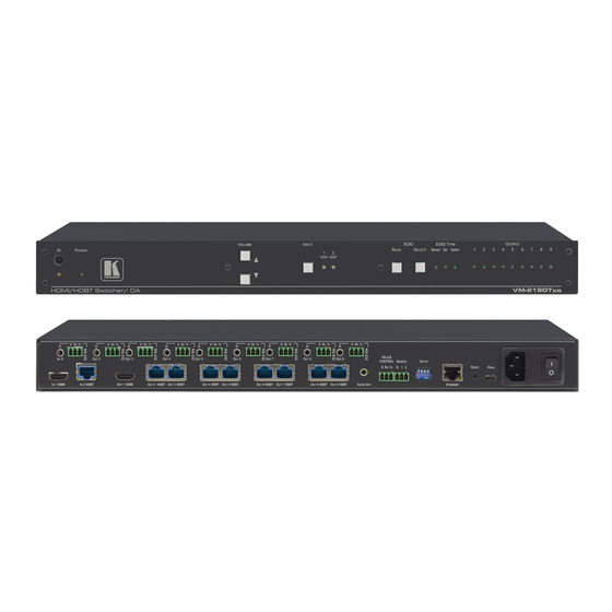
Defining VM-218DTxr HDMI/HDBT Switcher DA VM-218DTxr VM-218DT appear identical. This section defines VM-218DTxr. Figure 1: VM-218DTxr HDMI/HDBT Switcher DA Front Panel Feature Function IR LED Lights orange when the unit accepts IR remote commands. IR Sensor Use to control a peripheral device connected to OUT 2 HDBT with that device’s remote controller. - Page 8 TP-580R for VM-218DT). AUDIO OUT 3.5mm Mini Connect to an analog audio acceptor. Jack RS-232 CONTROL 3-pin Connect to the serial controller to control the VM-218DTxr. Terminal Block REMOTE 3-pin Terminal For future use. Block SETUP DIP-switches Use to set the device behavior.
-
Page 9: Installing In A Rack
Kramer Electronics Ltd. Installing in a Rack This section provides instructions for rack mounting VM-218DTxr. Before installing in a rack, verify that the environment is within the recommended range: • Operation temperature – 0 to 40C (32 to 104F). •... -
Page 10: Connecting The Hdmi/Hdbt Switcher Da
Ethernet signals, therefore the connecting procedures in this section are described separately for each device. Always switch off the power to each device before connecting it to your VM-218DTxr. After connecting your VM-218DTxr, connect its power and then switch on the power to each device. -
Page 11: Connecting Vm-218Dt
Figure 1. Connect an HDMI source (for example, a Blu-ray player) to the IN 1 HDMI connector 2. Connect an HDBT transmitter (for example, Kramer TP-580T) to the IN 2 HDBT RJ-45 connector 3. Connect the OUT 1 HDMI connector to an HDMI acceptor (for example, a display). -
Page 12: Extending Control Signals
VM-218DTxr only) to control a peripheral device. Figure 3 (for VM-218DTxr) and Figure 4 (for VM-218DT) show several types of signal extensions for each HDBT device, for illustrating device capabilities only. IR Extension Use the IR 3.5mm mini jacks for the HDBT input... - Page 13 RS-232 control signals between any set of RS-232 ports on the HDBT transmitter and receivers. To extend an RS-232 signal, for example, from VM-218DTxr to Projector B: 1. Connect OUT 5 RS-232 3-pin terminal block connector to a room controller (for example,...
-
Page 14: Controlling Vm-218Dtxr Via Rs-232 Control
Controlling VM-218DTxr via RS-232 CONTROL VM-218DTxr features an RS-232 CONTROL 3-pin terminal block connector allowing the RS-232 to control the VM-218DTxr. To do so, connect the VM-218DTxr to a controller (for example a PC) via the RS-232 CONTROL terminal block on the rear panel as follows: •... -
Page 15: Setting The Dip-Switches
On (down) – Disable audio de-embedding and enable pass-through of all audio formats. Note that the analog audio output port is muted. Off (up) – Normal mode (default). Force RGB On (down) – Force RGB mode. VM-218DTxr, VM-218DT – Connecting the HDMI/HDBT Switcher DA... -
Page 16: Cascading Devices
3. Connect the OUT 1 HDMI connector on the primary device to the IN 1 HDMI connector on the cascaded DA device. 4. After powering the cascaded device, make sure that the HDMI input is selected on the cascaded device. Figure 5: Cascading DAs VM-218DTxr, VM-218DT – Connecting the HDMI/HDBT Switcher DA... -
Page 17: Operating And Controlling The Vm-218Dtxr
You can acquire the EDID using: • The front panel buttons (see Acquiring EDID via the Front Panel Buttons on page 16) • The embedded web pages (see Managing EDID on page 24) VM-218DTxr, VM-218DT – Operating and Controlling the VM-218DTxr... -
Page 18: Using The Ethernet
Supports EDID Designer (via the mini USB port) that can be loaded from our Web site: Kramer EDID Designer. To use the mini USB port, you need to download and the Kramer USB driver from our Web site at: www.kramerav.com/support/product_downloads.asp install it. - Page 19 4. Highlight either Internet Protocol Version 6 (TCP/IPv6) or Internet Protocol Version 4 (TCP/IPv4) depending on the requirements of your IT system. 5. Click Properties. The Internet Protocol Properties window relevant to your IT system appears as shown in Figure 7 Figure VM-218DTxr, VM-218DT – Operating and Controlling the VM-218DTxr...
- Page 20 6. Select Use the following IP Address for static IP addressing and fill in the details as shown in Figure For TCP/IPv4 you can use any IP address in the range 192.168.1.1 to 192.168.1.255 (excluding 192.168.1.39) that is provided by your IT department. VM-218DTxr, VM-218DT – Operating and Controlling the VM-218DTxr...
- Page 21 8. Click Close. Connecting the Ethernet Port via IP LAN You can connect the Ethernet port of the VM-218DTxr, via IP LAN, to the Ethernet port on a network hub or using a straight-through cable with RJ-45 connectors. Configuring the Ethernet Port You can set the Ethernet parameters via the embedded Web pages.
-
Page 22: Using The Embedded Web Pages
2. Type the IP number of the device in the Address bar of your browser. For example, the default IP number: The Authentication window appears (if set, security is enabled): Figure 10: Using the Embedded Web Pages – The Authentication Window VM-218DTxr, VM-218DT – Using the Embedded Web Pages... - Page 23 24. • Setting Web Page Access Permission on page 29. • Changing Device Settings on page 31. • Upgrading the Firmware on page 33. • Viewing the About Page on page 34. VM-218DTxr, VM-218DT – Using the Embedded Web Pages...
-
Page 24: Switching The Inputs And Setting The Output Volume
1. In the Navigation pane, click Switching. The Switching page appears. 2. Use the slider to set the Analog Output Volume (0dB, by default). 3. If required, click to mute/unmute the output. VM-218DTxr, VM-218DT – Using the Embedded Web Pages... -
Page 25: Defining Video And Audio Settings
Setting HDCP support to disabled on the HDMI input allows the source to transmit a non-HDCP signal if required (for example, when working with a Mac computer). HDCP mode is set per input. VM-218DTxr, VM-218DT – Using the Embedded Web Pages... -
Page 26: Setting The Output Labels
2. Type the new output label and click Managing EDID Use the EDID page to read the EDID from: ▪ Any of the inputs. ▪ Any of the outputs. ▪ The default EDID. VM-218DTxr, VM-218DT – Using the Embedded Web Pages... - Page 27 Kramer Electronics Ltd. You can also load an external custom EDID file from your PC onto the VM-218DTxr. The selected EDID can be copied to the selected input/s. View the currently selected EDID source Bytemap by clicking Bytemap on the right side.
- Page 28 2. Select the EDID source (for example, one of the inputs). If you are reading EDID from an output, make sure that that output is connected to an acceptor. Figure 15: EDID Management Page – Select an EDID Input (Read From) VM-218DTxr, VM-218DT – Using the Embedded Web Pages...
- Page 29 Kramer Electronics Ltd. 3. Select the input/s (or all the inputs) to which the EDID is copied. Figure 16: EDID Management Page – Select the Inputs (Copy To) VM-218DTxr, VM-218DT – Using the Embedded Web Pages...
- Page 30 1. In the Navigation pane, click EDID Management. The EDID Management page appears. 2. Click Default. 3. Select the input/s (or all the inputs) to which the default EDID is copied. 4. Click Copy and follow the instructions on-screen. VM-218DTxr, VM-218DT – Using the Embedded Web Pages...
-
Page 31: Setting Web Page Access Permission
1. In the Navigation pane, click Authentication. The Authentication page appears. 2. Type current password and then type the new password twice. 3. Click Change to store the new password. The following message appears: Figure 20: Authentication – Reloading Web Page VM-218DTxr, VM-218DT – Using the Embedded Web Pages... - Page 32 1. In the Navigation pane, click Authentication. The Authentication page appears. 2. Click Enabled. The following message appears: Figure 23: [Figure Caption] 3. Click OK. The page reloads, and authentication is required. VM-218DTxr, VM-218DT – Using the Embedded Web Pages...
-
Page 33: Changing Device Settings
Factory Reset on page 33. Changing the Ethernet Settings To change the Ethernet settings: 1. In the Navigation pane, click Device Settings. The Device Settings page appears: Figure 24: The Device Settings Page VM-218DTxr, VM-218DT – Using the Embedded Web Pages... - Page 34 2. Click Load and browse for the configuration file. 3. Select the configuration file and click Open. The configuration file is uploaded, and the following message appears: Figure 26: Device Settings – Configuration Uploaded 4. Click OK. VM-218DTxr, VM-218DT – Using the Embedded Web Pages...
-
Page 35: Upgrading The Firmware
Figure 28: Firmware Upgrade Page – Selecting the New Firmware File 2. Click Update and select the new firmware file from the new firmware folder. Figure 29: Firmware Upgrade Page – Update Warning Message VM-218DTxr, VM-218DT – Using the Embedded Web Pages... -
Page 36: Viewing The About Page
5. Make sure that the new version appears in the Firmware Upgrade page. Viewing the About Page In the Navigation pane, click About to view the VM-218DTxr Web page version and Kramer Electronics Ltd details. Figure 31: About Page VM-218DTxr, VM-218DT – Using the Embedded Web Pages... -
Page 37: Upgrading The Firmware
The latest version of K-UPLOAD and installation instructions can be downloaded from our website at: www.kramerav.com/support/product_downloads.asp. Note that in order to use the micro USB port, you need to install the Kramer USB driver, available at: www.kramerav.com/support/product_downloads.asp. VM-218DTxr, VM-218DT – Upgrading the Firmware... -
Page 38: Technical Specifications
100-240V AC, 50/60Hz Environmental Operating Temperature 0° to +40°C (32° to 104°F) Conditions Storage Temperature -40° to +70°C (-40° to 158°F) Humidity 10% to 90%, RHL non-condensing Regulatory Safety CE, FCC Compliance Environmental RoHs, WEEE VM-218DTxr, VM-218DT – Technical Specifications... -
Page 39: Default Communication Parameters
Front panel buttons: power off the device, press and hold the RESET button for 3 seconds while powering the device, and then release. “#factory” command. Protocol 3000: Web Pages: In the Device Settings page, click Reset. Web Page Authentication User/Password: Admin/Admin VM-218DTxr, VM-218DT – Technical Specifications... -
Page 40: Default Edid
720 x 480p at 60Hz - EDTV (4:3, 8:9) 720 x 480i at 60Hz - Doublescan (16:9, 32:27) 720 x 576i at 50Hz - Doublescan (16:9, 64:45) 640 x 480p at 60Hz - Default (4:3, 1:1) NB: NTSC refresh rate = (Hz*1000)/1001 VM-218DTxr, VM-218DT – Default EDID... - Page 41 Front left/right center.. No Rear left/right center... No Rear LFE....No Report information Date generated... 18/02/2016 Software revision..2.60.0.972 Data source....File Operating system..6.1.7601.2.Service Pack 1 Raw data 00,FF,FF,FF,FF,FF,FF,00,2D,B2,00,12,01,01,01,01,FF,18,01,04,80,34,20,78,E2,B3,25,AC,51,30,B4,26, 10,50,54,FF,FF,80,81,8F,81,99,A9,40,61,59,45,59,31,59,71,4A,81,40,01,1D,00,72,51,D0,1E,20,6E,28, 55,00,07,44,21,00,00,1E,00,00,00,FF,00,32,39,35,2D,38,38,33,34,35,30,31,30,30,00,00,00,FC,00,56, 4D,2D,32,31,34,44,54,20,20,20,20,20,00,00,00,FD,00,38,4C,1E,53,11,00,0A,20,20,20,20,20,20,01,DF, 02,03,1B,C1,23,09,07,07,48,10,05,84,03,02,07,16,01,65,03,0C,00,10,00,83,01,00,00,02,3A,80,18,71, 38,2D,40,58,2C,45,00,07,44,21,00,00,1E,01,1D,80,18,71,1C,16,20,58,2C,25,00,07,44,21,00,00,9E,01, 1D,00,72,51,D0,1E,20,6E,28,55,00,07,44,21,00,00,1E,8C,0A,D0,8A,20,E0,2D,10,10,3E,96,00,07,44,21, 00,00,18,00,00,00,00,00,00,00,00,00,00,00,00,00,00,00,00,00,00,00,00,00,00,00,00,00,00,00,00,77 VM-218DTxr, VM-218DT – Default EDID...
-
Page 42: Protocol 3000
Kramer Electronics Ltd. Protocol 3000 Kramer devices can be operated using Kramer Protocol 3000 commands sent via serial or Ethernet ports. Understanding Protocol 3000 Protocol 3000 commands are a sequence of ASCII letters, structured according to the following. • Command format:... -
Page 43: Protocol 3000 Commands
– TCP/UDP ETH-PORT? Get Ethernet port COMMAND Get the Ethernet port protocol 0 – TCP protocol. #ETH-PORT?portType<CR> for UDP: #ETH-PORT?1<CR> 1 – UDP FEEDBACK – TCP / UDP port number ETHPort ~nn@ETH-PORTportType,ETHPort<CR><LF> (0 – 65535) VM-218DTxr, VM-218DT – Protocol 3000... - Page 44 Get command list or help COMMAND Get the command list: #HELP<CR> #HELP<CR> for specific command. command #HELPcommand_name<CR> To get help for FEEDBACK AV-SW-TIMEOUT: 1. Multi-line: HELPAV-SW-TIMEOUT<CR> ~nn@Devicecommand,command…<CR><LF> To get help for command use: HELP (COMMAND_NAME)<CR><LF> ~nn@HELPcommand:<CR><LF> description<CR><LF> USAGE:usage<CR><LF> VM-218DTxr, VM-218DT – Protocol 3000...
- Page 45 FEEDBACK The machine name is ~nn@NAMEmachine_name<CR><LF> not the same as the model name. The machine name is used to identify a specific machine or a network in use (with DNS feature on). VM-218DTxr, VM-218DT – Protocol 3000...
- Page 46 Set the gateway IP address to 192.168.0.1: #NET-GATEip_address<CR> xxx.xxx.xxx.xxx A network gateway #NET- FEEDBACK connects the device via GATE192.168.000.001<CR ~nn@NET-GATEip_address<CR><LF> another network and > maybe over the Internet. Be careful of security issues. For proper settings consult your network administrator. VM-218DTxr, VM-218DT – Protocol 3000...
- Page 47 6 – OUT 6 HDBT 7 – OUT 7 HDBT 8 – OUT 8 HDBT 9 – OUT 9 HDBT * – ALL x – disconnect – Source id 1 – IN 1 HDMI 2 – IN 2 HDBT VM-218DTxr, VM-218DT – Protocol 3000...
- Page 48 COMMAND number. #SN?<CR> digits, factory assigned #SN?<CR> FEEDBACK ~nn@SNserial_number<CR><LF> – XX.XX.XXXX firmware_version VERSION? Get firmware version COMMAND Get the device firmware number. #VERSION?<CR> where the digit groups are: version number: major.minor.build version #VERSION?<CR> FEEDBACK ~nn@VERSIONfirmware_version<CR><LF> VM-218DTxr, VM-218DT – Protocol 3000...
-
Page 49: Result And Error Codes
ERR_RESERVED_8 (Reserved) ERR_RESERVED_9 (Reserved) ERR_RESERVED_10 (Reserved) ERR_RESERVED_11 (Reserved) ERR_RESERVED_12 (Reserved) ERR_EDID_CORRUPTED EDID corrupted ERR_NON_LISTED Device specific errors File has the same CRC – no changed ERR_SAME_CRC ERR_WRONG_MODE Wrong operation mode ERR_NOT_CONFIGURED Device/chip was not initialized VM-218DTxr, VM-218DT – Protocol 3000... - Page 50 Electronics products, this product must be insured during shipment, with the insurance and shipping charges prepaid by you . If this product is returned uninsured, you assume all risks of loss or damage during shipment. Kramer Electronics will not be responsible for any costs r elated to the removal or re- installation of this product from or into any installation.
- Page 51 SAFETY WARNING Disconnect the unit from the power supply before opening and servicing For the latest information on our products and a list of Kramer distributors, visit our Web site where updates to this user manual may be found. We welcome your questions, comments, and feedback.
Need help?
Do you have a question about the VM-218DTxr and is the answer not in the manual?
Questions and answers