Advertisement
Quick Links
Remote Tuner Options
for the
DXE-MBVE-1
Vertical Antenna
DXE-MBVE-1UGBRT3
for the MFJ-993BRT
300 Watt Remote Tuner
DXE-MBVE-1UGBRT4
for the MFJ-994BRT
600 Watt Remote Tuner
DXE-MBVE-1UGRT8
for the MFJ-998RT
1500 Watt Remote Tuner
DXE-MBVE-1-RT-INS Revision 1
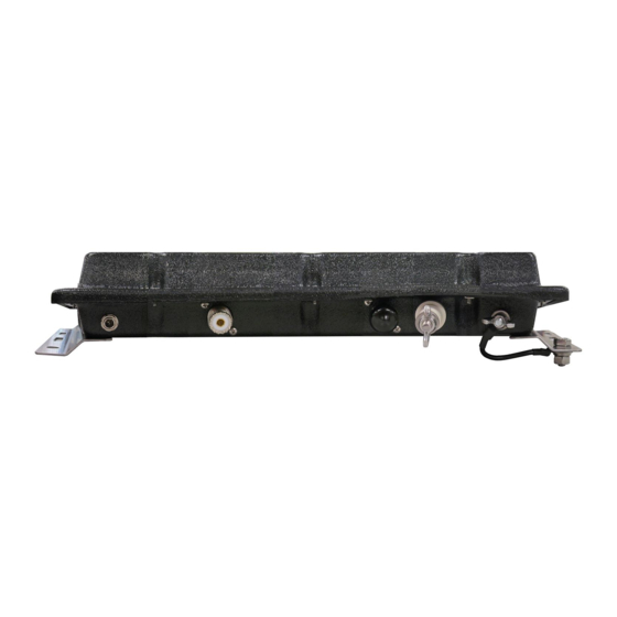
MFJ-993/994BRT Shown
MFJ-998RT Shown
© DX Engineering 2019
1200 Southeast Ave. - Tallmadge, OH 44278 USA
Phone: (800) 777-0703 - Tech Support and International: (330) 572-3200
Fax: (330) 572-3279 - E-mail:
DXEngineering@DXEngineering.com
Advertisement

Related Manuals for DX Engineering DXE-MBVE-1UGBRT3


Summary of Contents for DX Engineering DXE-MBVE-1UGBRT3
- Page 1 MFJ-998RT 1500 Watt Remote Tuner DXE-MBVE-1-RT-INS Revision 1 MFJ-993/994BRT Shown MFJ-998RT Shown © DX Engineering 2019 1200 Southeast Ave. - Tallmadge, OH 44278 USA Phone: (800) 777-0703 - Tech Support and International: (330) 572-3200 Fax: (330) 572-3279 - E-mail: DXEngineering@DXEngineering.com...
- Page 2 DXE-MBVE-1 multi-band vertical antenna system. There are 5 complete DXE-MBVE-1 antenna systems for use with MFJ the Remote Tuners. These packages include the DXE-MBVE-1 antenna with mounting hardware and remote tuner options: DX Engineering DXE-MBVE- DXE-MBVE-1-...
- Page 3 DXE-MBVE-1-UGHW Parts Listing DXE-MBVE-1UGHW Upgrade Insulator Hardware Kit For the MFJ-993BRT/MFJ-994BRT/MFJ-998RT Tuner mounting option Insulator, Black, Delrin, MBVE-1 Conversion #10 Self Tapping Screw (requires customer supplied 11/16” drill bit) 10” Wire Assembly, 12 ga, Black Insulated, two `1/4” ring terminals DXE-MBVE-THW Parts Listing DXE-MBVE-THW Mounting Hardware Kit For the MFJ-993BRT/MFJ-994BRT Tuner mounting option...
- Page 4 Basic Installation for all remote tuner models 1. Disconnect your coaxial cable that is connected to the UNUN. Remove the UNUN, UNUN mounting bracket and the braided feedline connections from the DXE-MBVE-1 antenna. The UNUN will not be used when the remote tuner is installed. 2.
- Page 5 Steps A1 through A7 are specific to the MFJ-993BRT or MFJ-994BRT remote tuner options. (See step B1 for the MFJ-998RT remote tuner option) A1. Tilt the base section and re-install the antenna upper sections onto the black insulator. Using the new Studded band clamp, lightly tighten the clamp in place as shown. Once this is done, raise the antenna back up to easily work on the rest of the installation.
- Page 6 A5. Place on 5/16” External Tooth Washer on each leg of the upper saddle clamp U-bolt and then position the MFJ-993BRT or MFJ-994BRT tuner in place on the upper U-bolt that protrudes from the saddle clamp. Once in place, loosely install the two 5/16” Flat Washers, two 5/16” Split Lock Washers and two 5/16”-18 Hex Nuts to hold the tuner in place on the upper clamp as shown.
- Page 7 A7. When the upper antenna parts are mounted to the base assembly (see previous installation instructions), install the Studded Band Clamp on the first element just above the black insulator with the stud facing the side nearest the tuner connections. Install the 10” long tuner wire on the studded band clamp using the #10 hardware as shown.
- Page 8 B3. With the U-bolts loose, you can slip the assembly onto the lower base tube. Position the top U-bolt 4-1/2” below the top of the base tube as shown. (Refer to Page 40 for photos showing the positioning of the clamps and tuner). Once positioned correctly, tighten all of the hardware holding the tuner shelf assembly to the lower base tube.
- Page 9 B6. When the upper antenna parts are mounted to the base assembly (see previous installation instructions), install the Studded Band Clamp on the first element just above the black insulator with the stud facing the side nearest the tuner connections. Install the 10” long tuner wire from the studded band clamp using the #10 hardware.
- Page 10 - 9 -...
- Page 11 Bias Tee Information The MFJ-4117 Bias Tee is included with the MFJ Remote Tuner. Since the coaxial cable is supplying the DC voltage to the remote tuner (injected in the coaxial cable by the Bias Tee), the coaxial cable used must have a good DC path. Lightning protectors that block DC cannot be used.
-
Page 12: Technical Support
All products manufactured by DX Engineering are warranted to be free from defects in material and workmanship for a period of one (1) year from date of shipment. DX Engineering’s sole obligation under these warranties shall be to issue credit, repair or replace any item or part thereof which is proved to be other than as warranted; no allowance shall be made for any labor charges of Buyer for replacement of parts, adjustment or repairs, or any other work, unless such charges are authorized in advance by DX Engineering.
Need help?
Do you have a question about the DXE-MBVE-1UGBRT3 and is the answer not in the manual?
Questions and answers