Leuze electronic MLC 530 Original Operating Instructions
Safety light curtains
Hide thumbs
Also See for MLC 530:
- Original operating instructions (69 pages) ,
- Safe implementation and operation (60 pages) ,
- Original operating instructions (56 pages)

Related Manuals for Leuze electronic MLC 530


Summary of Contents for Leuze electronic MLC 530
- Page 1 MLC 530 Safety light curtains S A F E I M P L E M E N T A T I O N A N D O P E R A T I O N O r i g i n a l o p e r a t i n g i n s t r u c t i o n s...
- Page 2 © 2013 Leuze electronic GmbH + Co. KG In der Braike 1 D-73277 Owen / Germany Phone: +49 7021 573-0 Fax: +49 7021 573-199 http://www.leuze.com info@leuze.de Leuze electronic MLC 530...
-
Page 3: Table Of Contents
3.3.2 Operating indicators on the MLC 530 receiver ....... . . - Page 4 7.1.2 MLC 530 receiver ........
- Page 5 EC Declaration of Conformity..........97 Leuze electronic MLC 530...
-
Page 6: About This Document
Brief description of the safety sensor, consisting of transmitter and receiver MTTF Mean time to a dangerous failure (Mean Time To dangerous Failure) Muting Temporary automatic suppression of the safety functions OSSD Safety-related switching output (Output Signal Switching Device) Leuze electronic MLC 530... -
Page 7: Checklists
The checklists contain minimum testing requirements. Depending on the application, other tests may be necessary. Leuze electronic MLC 530... -
Page 8: Safety
Make certain that the safety sensor is correctly connected and that the protective function of the pro- tective device is ensured. Make certain that, during all conversions, maintenance work and inspections, the system is securely shut down and protected against being restarted. Leuze electronic MLC 530... -
Page 9: Proper Use
• adhering to all regulations and directives for the safe starting-up of the machine 1. They perform a task related to the subject matter shortly thereafter and keep their knowledge up to date through continuous further training. Leuze electronic MLC 530... -
Page 10: Disclaimer
• adhering to all regulations and directives for labor protection and safety at work • regular testing by competent persons Disclaimer Leuze electronic GmbH + Co. KG is not liable in the following cases: • safety sensor is not used as intended • safety notices are not adhered to •... -
Page 11: Device Description
Table 3.1: Device models in the series with specific features and functions Transmitter Receivers Basic Standard Extended MLC 500 MLC 510 MLC 520 MLC 530 MLC 501 MLC 511 OSSDs (2x) Transmission channel changeover ... -
Page 12: Connection Technology
The transmitter and receiver feature an M12 connector as an interface to the machine control with the following number of pins: Device version Device type Device plug MLC 500 Transmitter 5-pin MLC 530 Extended receiver 8-pin Leuze electronic MLC 530... -
Page 13: Display Elements
10 s long after switch-on: reduced range selected by the wiring of pin 4 Transmission channel C1 Transmission channel C2 3.3.2 Operating indicators on the MLC 530 receiver Three LEDs and a 7-segment display for visualizing the operating state are located on the receiver: Leuze electronic MLC 530... - Page 14 Device description LED1, red/green LED2, yellow LED3, blue OSSD icon RES icon Blanking/muting icon 7-segment display Figure 3.4: Indicators on the MLC 530 receiver Table 3.3: Meaning of the LEDs Color State Description Red/green Device switched off OSSD off Red slowly flashing External fault (approx.
-
Page 15: Alignment Display
Segment Description Switched on All beams in the beam area are free. Flashing At least one, but not all beams in the beam area are free. Switched off All beams in the beam area are interrupted. Leuze electronic MLC 530... - Page 16 Device description When the protective field has been free for about 5 s, the device switches back to the display of the oper- ating mode. Leuze electronic MLC 530...
-
Page 17: Functions
For access guarding, the start/restart interlock function is mandatory. The protective device may only be operated without start/restart interlock in certain exceptional cases and under certain conditions acc. to EN ISO 12100. Leuze electronic MLC 530... -
Page 18: Edm Contactor Monitoring
After the reset button has been actuated, the safety sensor switches to the ON state. EDM contactor monitoring The MLC 530 safety sensor works in all operating modes without the EDM function. In case you need this function: Use a suitable Safety Relay. -
Page 19: Range Reduction
(MultiScan factor) is deter- in several consecutive mined by the receiver to be the maxi- scans mum possible value depending on the number of beams, so that the maximum response time is 99 ms (fixed value). Leuze electronic MLC 530... -
Page 20: Linkage
Impairment of the protective function due to faulty signals Series connection of devices with safety-related switching outputs (OSSDs) may only be created with the following Leuze electronic safety sensors: SOLID-2/2E, SOLID-4/4E, MLD 300, MLD 500, MLC 300, plus MLC 500, RS4, RD800 or COMPACT... -
Page 21: Blanking, Reduced Resolution
Select operating mode 1, 2 or 3 (see chapter 7 „Electrical connection“). Fixed blanking with beam tolerance Fixed blanking with beam tolerance is used in operating modes 4 and 6 for access guarding, for example to blank a roller conveyor so that it is resistant to interference. Leuze electronic MLC 530... - Page 22 Press the teach key switch again and release it within 0.15 s and 4 s. The teach event ends. LED3 illuminates blue if at least one beam area is blanked. All objects have been correctly taught. Leuze electronic MLC 530...
-
Page 23: Floating Blanking
Add the scanning time needed for the largest beam area with floating blanking to the response time (see chapter 6.1.5 „Resolution and safety distance for fixed and floating blanking as well as reduced resolution“). Leuze electronic MLC 530... -
Page 24: Controlling Blanking
(see figure 4.4). WARNING Reduced resolution may result in serious injury! Take into consideration the reduced resolution when calculating the safety distance (see chapter 6.1.1). Leuze electronic MLC 530... -
Page 25: Timing Controlled Muting
Muting may not be initiated by a single sensor signal, nor may it be fully initiated by software signals. Danger zone Receiver Transmitter Muting sensor 1 Muting sensor 2 Figure 4.5: Arrangements of muting sensors for timing controlled 2-sensor muting in an exit application Leuze electronic MLC 530... - Page 26 • The signals of the two muting sensors are simultaneously inactive for a duration of more than 0.3 s. • The signal of a muting sensor is inactive for a duration of more than 4 s. • The muting time limit (10 min muting timeout) has elapsed. Leuze electronic MLC 530...
-
Page 27: Partial Muting
If the safety sensor responds with an error message, perform an error reset (see chapter 4.9 „Error reset“). Press and release the reset button within 0.15 to 4 s. Press the reset button a second time and keep it pressed down. The safety sensor switches on. Leuze electronic MLC 530... -
Page 28: Error Reset
1, 2 and 3 deactivated Acknowledging with the reset button or alterna- tively switching the voltage supply on and off 4 and 6 activated Acknowledging with the reset button or alterna- tively switching the voltage supply on and off Leuze electronic MLC 530... -
Page 29: Applications
In contrast, when floating blanking is active, the object can move in the blanked beam area, see chapter 4.7.2 „Floating blanking“. When reduced resolution is active, beams can be interrupted if adjacent beams are active and effective, see chapter 4.7.4 „Reduced resolution“. Leuze electronic MLC 530... -
Page 30: Access Guarding
Access guarding on a transfer path 5.2.1 Muting Access guarding can be operated with a bridging function for material transport through the protective field. In this case, the integrated muting function is used, see chapter 4.8 „Timing controlled muting“ Leuze electronic MLC 530... -
Page 31: Danger Zone Guarding
Risk of injury due to inadmissible application of blanking! Blanking is not permitted with danger zone guarding since the blanked areas would form accessible bridges to the danger zone. Do not use blanking for danger zone guarding. Leuze electronic MLC 530... -
Page 32: Mounting
= Response time of the Safety Relay = Stopping time of the machine [mm] = Additional distance to the safety distance If longer stopping times are determined during regular inspections, an appropriate additional time must be added to t Leuze electronic MLC 530... -
Page 33: Rt Ro
= Stopping time of the machine [mm] = Additional distance for access guarding with approach reaction with resolutions of 14 to 40 mm, d = resolution of protective device C = 8 (d - 14) mm. Additional dis- Leuze electronic MLC 530... - Page 34 = Response time of the Safety Relay = Stopping time of the machine [mm] = Additional distance in which a body part can move towards the protective device before the protective device triggers: value (see table 6.1) Leuze electronic MLC 530...
- Page 35 Additional distance C to the danger zone [mm] 2600 2500 2400 2200 2000 1800 1100 1100 1600 1150 1150 1100 1000 1400 1200 1200 1100 1000 1200 1200 1200 1100 1000 1000 1200 1150 1050 1150 1050 1050 Leuze electronic MLC 530...
- Page 36 1400 mm; the point of operation is located at a height of 1000 mm Additional distance C to the point of operation is 700 mm (see table 6.1). Calculate safety distance S using the formula acc. to EN ISO 13855. Leuze electronic MLC 530...
-
Page 37: Calculation Of Safety Distance S For Parallel Approach To The Protective Field
= 1461 The safety distance of 1350 mm is not sufficient; 1460 mm are necessary. This is why the calculation is repeated with a protective field height of 1500 mm. The response time is now 14 ms. Leuze electronic MLC 530... - Page 38 [mm/s] = 1600 = (0.140 + 0.013 + 0.010) [mm] = 1200 - 0.4 300 [mm] = 1600 mm/s 0.163 s + 1080 mm [mm] = 1341 Leuze electronic MLC 530...
-
Page 39: Minimum Distance To Reflective Surfaces
Distance (b) transmit- Calculation of the minimum distance (a) to reflective surfaces ter-receiver a [mm] = 131 b > 3 m a [mm] = tan(2.5°) 1000 b [m] = 43.66 b [m] Leuze electronic MLC 530... -
Page 40: Resolution And Safety Distance For Fixed And Floating Blanking As Well As Reduced Resolution
= (L 25 mm 0.2 ms) + 1 ms 90 mm = (L 75 mm 0.2 ms) + 1 ms = length of the largest protective field area with floating blanking in mm Leuze electronic MLC 530... -
Page 41: Preventing Mutual Interference Between Adjacent Devices
Prevent optical crosstalk between adjacent devices. Mount adjacent devices with a shield between them or install a dividing wall to prevent mutual interfer- ence. Mount the adjacent devices opposite from one another to prevent mutual interference. Leuze electronic MLC 530... -
Page 42: Arrangement Of The Muting Sensors
If accessible distances exist between the transport material and the safety sensor, PS mats or wicket gates monitored with Safety Switches have been tried, tested and proven as additional safeguards. Such measures prevent injuries caused, for example, by crushing in the access ar- Leuze electronic MLC 530... -
Page 43: Basic Information
The signals can be generated by e.g. optoelectronic sensors from Leuze electronic. Any transducers which output a +24 VDC switching signal when detecting the permitted transport material can still be used as muting sensors: •... -
Page 44: Arrangement Of The Muting Sensors For Timing Controlled 2-Sensor Muting
This prevents muting from being triggered unintentionally. With this arrangement, an object can be transported through the protective field in both directions. Muting accessories from Leuze electronic, for example Muting Sensor Sets and matching Device Columns, facilitate the installation of muting applications significantly. - Page 45 This prevents—or makes more difficult—manipulation with the feet since the protective field is interrupted before the muting-sensor light beam. To increase safety and make manipulation more difficult, MS1 and MS2 should, if possible, be mounted at different heights (i.e. no point-shaped intersection of the light beams). Leuze electronic MLC 530...
-
Page 46: Arrangement Of The Muting Sensors For Timing Controlled 2-Sensor Muting Especially For Exit
Do the protective field height and dimensions satisfy the requirements of EN 13855? Is the safety distance to the point of operation maintained (see chapter 6.1.1)? Is the minimum distance to reflective surfaces maintained (see chapter 6.1.4)? Leuze electronic MLC 530... -
Page 47: Definition Of Directions Of Movement
Turning: movement around the longitudinal axis Tilting: lateral turning movement diagonal to the front screen Pitching: lateral turning movement in the direction of the front screen Figure 6.10: Directions of movement during alignment of the safety sensor Leuze electronic MLC 530... -
Page 48: Fastening Via Bt-Nc60 Sliding Blocks
The full resolution of the safety sensor is thus preserved on all points of the protective field down to the machine table. Leuze electronic MLC 530... -
Page 49: Mounting Accessories
While AC-SCM8 is the connection module in the stan- dard housing which is mounted directly on the machine via the M4 screws, the AC-SCM8-BT also contains a mounting plate which opens up further mounting options: Leuze electronic MLC 530... -
Page 50: Deflecting Mirror For Multiple-Side Guarding
Deflecting Mirror for multiple-side guarding For multiple-side guarding, redirecting the protective field with one or two Deflecting Mirrors is economical. To do this, Leuze electronic supplies • the UM60 Deflecting Mirror for mounting on the machine in various lengths (see table 15.5) •... -
Page 51: Mlc-Ps Protective Screen
10%. Mounting bracket sets with 2 and 3 clamp brackets are available. If the length equals 1200 mm or higher, 3 clamp brackets are recommended. Leuze electronic MLC 530... - Page 52 Mounting Figure 6.18: MLC-PS protective screen fastened with MLC-2PSF clamp bracket Leuze electronic MLC 530...
-
Page 53: Electrical Connection
• VIN1 = 0 V, VIN2 = +24 V: transmission channel C2 The wiring of pin 4 determines the transmitting power and thereby the range: • Pin 4 = +24 V: standard range • Pin 4 = 0 V or open: reduced range Leuze electronic MLC 530... -
Page 54: Mlc 530 Receiver
NOTICE Device connection Use shielded cables for device connection 7.1.2 MLC 530 receiver Table 7.2: MLC 530 receivers are equipped with an 8-pin M 12 connector. Figure 7.4: Pin assignment receiver MLCx30R Figure 7.5: Connection diagram receiver Leuze electronic... -
Page 55: Ac-Scm8 Sensor Connection Module
Electrical connection Table 7.3: MLC 530 receiver pin assignment Core color (CB-M12-xx000E-5GF) Receivers white IO1 - control-input function selection, control- input reset button, signal output brown VIN1 - supply voltage green IN3 - control input yellow IN4 - control input... -
Page 56: Operating Mode 1
Bridge to pin 8 +24 V (IN8) (IN8) 3 (IN3) +24 V 4 (IN4) +24 V Normal closed contact between “Active/inactive blanking” switch and device Normal closed contact between existing “Active/ inactive blanking” wiring and device Leuze electronic MLC 530... - Page 57 Linked safety sensor, e.g. moveable guard switch Key switch for teaching (“teach key switch”) Figure 7.6: Operating mode 1: circuit diagram example of linkage with position switch for monitoring for the presence of machine parts with fixed blanking Leuze electronic MLC 530...
- Page 58 Key switch for teaching (“teach key switch”) Figure 7.7: Operating mode 1: circuit diagram example with manual protective field changeover for ac- tivating/deactivating fixed blanking areas MLC 500 transmitter MLC 530 receiver AC-SCM8 sensor connection module S200 Safety Position Switch CB-M12-X000E-2GF/GM connection cable CB-M12-X000E-8GF connection cable...
-
Page 59: Operating Mode 2
4 (IN4) Bridge to pin 1 (IO1) 8 (IN8) OSSD2 from the Normal closed contact between upstream device electronic safety-related switch- ing outputs and device +24 V +24 V +24 V OSSD1 OSSD1 OSSD1 OSSD2 OSSD2 OSSD2 Leuze electronic MLC 530... -
Page 60: Operating Mode 3
CB-M12-X000E-8GF connection cable MSI-SR4 Safety Relay with RES and EDM CB-M12-X000E-5GF/GM connection cable Figure 7.10: Operating mode 2: connection example with MLC 530 and MLD 510 for combining point of operation and access guarding Operating mode 3 The following functions are summarized in function groups (FG) which can be selected by switching between IN4 and IN8. - Page 61 8 (IN8) +24 V Normal closed con- tact between protec- tive field inputs and device +24 V +24 V +24 V +24 V OSSD1 OSSD1 OSSD1 OSSD1 OSSD2 OSSD2 OSSD2 OSSD2 Leuze electronic MLC 530...
- Page 62 Figure 7.11: Operating mode 3: circuit diagram example of a linked, contact-based position switch for monitoring of the blanked object and a changeover switch for switching between function groups FG1 and FG2 MLC 500 transmitter MLC 530 receiver AC-SCM8 sensor connection module S300 position switch + changeover switch CB-M12-X000XE-2GF/GM connection cable...
-
Page 63: Operating Mode 4
0 V mut- ing ends) 4 (IN4) Muting signal 2 (+24 V muting begins, 0 V mut- ing ends) 8 (IN8) Bridge to pin 1 (IO1) +24 V +24 V +24 V OSSD1 OSSD1 OSSD1 OSSD2 OSSD2 OSSD2 Leuze electronic MLC 530... - Page 64 -MS2 -MS1 MLC500T MLC530R Figure 7.13: Operating mode 4: circuit diagram example for timing controlled 2-sensor muting MLC 500 transmitter MLC 530 receiver AC-SCM8 sensor connection module PRK 46B/4D.2-S12 muting sensor CB-M12-X000E-2GF/GM connection cable CB-M12-X000E-8GF connection cable AC-ABF-SL1 control unit CB-M12-X000E-3GF/GM connection cable Figure 7.14: Operating mode 4: connection example for timing controlled 2-sensor muting with control...
-
Page 65: Operating Mode 6
Muting signal 1 (+24 V muting begins, 0 V mut- ing ends) 8 (IN8) Muting signal 2 (+24 V muting begins, 0 V mut- ing ends) +24 V +24 V +24 V OSSD1 OSSD1 OSSD1 OSSD2 OSSD2 OSSD2 Leuze electronic MLC 530... - Page 66 -MS1 MLC530R MLC500T Figure 7.15: Operating mode 6: circuit diagram example with timing controlled 2-sensor muting (partial) � MLC 500 transmitter MLC 530 receiver AC-SCM8 sensor connection module PRK 46B/4D.2-S12 muting sensor CB-M12-X000E-2GF/GM connection cable CB-M12-X000E-8GF connection cable AC-ABF10 control unit...
-
Page 67: Starting Up The Device
Turn the receiver to the left until LED1 still flashes green but does not yet illuminate red. If necessary, you may have to turn the transmitter beforehand. The receiver with activated alignment display shows flashing segments in the 7-segment display, if applicable. Leuze electronic MLC 530... -
Page 68: Aligning Of Deflecting Mirrors With The Laser Alignment Aid
Now align the transmitter according to the same method, paying attention to the display elements of the receiver while doing so (see chapter 3.3.2 „Operating indicators on the MLC 530 receiver“). Aligning of Deflecting Mirrors with the laser alignment aid When using Deflecting Mirrors for multiple-side point of operation guarding and access guarding in partic- ular, an external laser alignment aid is recommended (see table 15.5). -
Page 69: Teaching Of Fixed Blanking Areas
• Accepting by actuating and releasing the teach key switch If the "Floating blanking" function is to be deselected, this can be managed by re-teaching a free protective field or a protective field with only stationary objects. Leuze electronic MLC 530... - Page 70 Start teaching - activate and release key switch Move all moving objects to be blanked within 60 s in their blanking areas End teaching - activate and release key switch Figure 8.1: Teaching floating and fixed blanking areas Leuze electronic MLC 530...
-
Page 71: Testing
Not until proper function of the Optoelectronic Protective Device is ascertained may it be integrated in the control circuit of the system. As a safety inspection, Leuze electronic offers testing by a competent person prior to the initial start-up in selected countries (see chapter 13). - Page 72 Are the notices for daily testing of the safety sensor legible to the operator and are they located in a highly visible location? Is the muting indicator visibly mounted on the entry/exit path in the case of a muting application? Leuze electronic MLC 530...
-
Page 73: To Be Performed Periodically By Competent Persons
Have all tests performed by competent persons. Observe the nationally applicable regulations and the time periods specified therein. As a safety inspection, Leuze electronic offers periodic testing by a competent person in selected countries (see chapter 13). Daily or at change of shift by the operator... - Page 74 (see figure 9.1) and ensure that the machine cannot be started with an interrupted light beam. Start the machine. Ensure that the dangerous state is stopped as soon as an active light beam is interrupted with a test object provided for this purpose. Leuze electronic MLC 530...
-
Page 75: Maintenance
Do not use chemical cleaners. Prerequisites for cleaning: • The system is safely shut down and protected against restart. Clean the safety sensor regularly depending on the degree of contamination. Leuze electronic MLC 530... -
Page 76: Rectifying The Fault
Analyze the cause of the error using the following tables (see table 11.1, see table 11.2, see table 11.3) and eliminate the error. If you are unable to rectify the fault, contact the Leuze electronic branch responsible for you or call the Leuze electronic customer service (see chapter 13 „Service and support“). - Page 77 A muting restart is Press the reset button to override the mut- required in operating ing zone. modes 4 and 6 blue, very quickly flash- Teaching of blankings Press the teach button again. still active Leuze electronic MLC 530...
-
Page 78: Error Messages 7-Segment Display
Locking voltage. Foreign transmitter detected Remove foreign transmitters and Locking increase the distance to the reflect- ing surfaces. Actuate the start but- ton if available. Ambient temperature too high Ensure correct environmental con- Automatic reset ditions Leuze electronic MLC 530... - Page 79 Automatic reset channel Linkage of electronic safety- Check the wiring. Automatic reset related switching outputs: OSSDs did not switch simultaneously. Linkage of electronic safety- Check the wiring. Automatic reset related switching outputs: OSSDs return no test pulses. Leuze electronic MLC 530...
- Page 80 2.5 min teach timeout Repeat the teach event. Fixed OSSD remains exceeded.Teach-in not finished or blanking: interrupt beams uniquely off. not finished correctly or release them. Floating blanking: move teach object slowly. Leuze electronic MLC 530...
-
Page 81: Muting Indicators
Flashing of the external muting indicator and quick flashing of the blue LED signal that no valid muting condition is present when the protective field is interrupted. Check whether the muting timeout has been exceeded or the concurrency condition (both muting sig- nals within 4 s) has not been met. Leuze electronic MLC 530... -
Page 82: Disposing
Disposing Disposing For disposal observe the applicable national regulations regarding electronic components. Leuze electronic MLC 530... -
Page 83: Service And Support
Monday to Thursday, 8.00 a.m. to 5.00 p.m. (UTC+1) Friday, 8.00 a.m. to 4.00 p.m. (UTC +1) E-mail: service.protect@leuze.de Return address for repairs: Service Center Leuze electronic GmbH + Co. KG In der Braike 1 D-73277 Owen / Germany Leuze electronic MLC 530... -
Page 84: Technical Data
Common value for ext. fuse in the supply line for transmitter 2 A semi time-lag and receiver Synchronization Optical between transmitter and receiver Safety class Protection class IP65 Temperature range, operation 0 … 55 °C Temperature range, storage -25 … 70 °C Leuze electronic MLC 530... - Page 85 300 mA 380 mA Residual current < 2 Load capacity Load inductivity Permissible wire resistance for load <200 Permissible wire cross section 0.25 mm Permissible cable length between receiver and load 100 m Leuze electronic MLC 530...
-
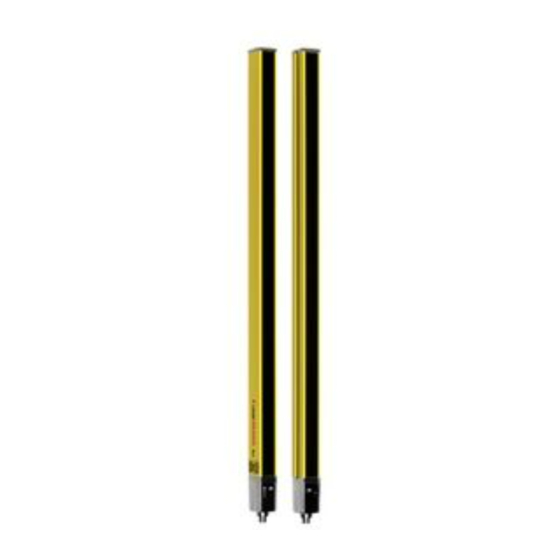
Page 86: Dimensions, Weight, Response Time
2 ms. Figure 14.1: Dimensions of transmitter and receiver Effective protective field height H goes beyond the dimensions of the optics area to the outer borders of the circles labeled with R. Leuze electronic MLC 530... - Page 87 MLC…-2550 2550 2616 2.70 MLC…-2700 2700 2766 2.85 MLC…-2850 2850 2916 3.00 MLC…-3000 3000 3066 3.15 a) H = nominal protective field height = length of the yellow housing part b) Total height, see figure 14.1 Leuze electronic MLC 530...
-
Page 88: Dimensional Drawings: Accessories
48 mm 30 mm 13 mm 49 mm 40 mm 19 mm 43 mm 90 mm 44 mm 18 mm 14.3 Dimensional drawings: accessories Figure 14.2: BT-L mounting bracket 12.1 10.8 Figure 14.3: BT-Z parallel bracket Leuze electronic MLC 530... - Page 89 Technical data Ø6,2 Ø6,2 Ø18 Ø18 Ø28 Ø28 Figure 14.4: BT-R swivel mount Figure 14.5: BT-P40 clamp bracket Leuze electronic MLC 530...
- Page 90 Technical data 26,5 ~26.5 11.3 11,3 Figure 14.6: BT-SSD and BT-SSD-270 swiveling mounting brackets Figure 14.7: AC-SCM8 sensor connection module Leuze electronic MLC 530...
-
Page 91: Ordering Information And Accessories
30 mm 40 mm 90 mm field height MLC500T14- MLC500T20- MLC500T30- MLC500T40- MLC500T90- hhhh [mm] hhhh hhhh hhhh hhhh hhhh 68000101 68000201 68000301 68000401 68000202 68000302 68000402 68000103 68000203 68000303 68000403 68000104 68000204 68000304 68000404 68000904 Leuze electronic MLC 530... - Page 92 68000328 68000428 68000928 3000 68000130 68000230 68000330 68000430 68000930 Table 15.4: Article numbers of MLC 530 receiver depending on resolution and protective field height Protective 14 mm 20 mm 30 mm 40 mm 90 mm field height MLC530R14- MLC530R20- MLC530R30-...
- Page 93 Connection cable, 5-pin, 10 m long 678057 CB-M12-15000E-5GF Connection cable, 5-pin, 15 m long 678058 CB-M12-25000E-5GF Connection cable, 5-pin, 25 m long Connection cable for MLC 530 receiver, shielded 678060 CB-M12-5000E-8GF Connection cable, 8-pin, 5 m long 678061 CB-M12-10000E-8GF Connection cable, 8-pin, 10 m long...
- Page 94 Device Column, U-shaped, profile height 2500 mm Deflecting Mirror Columns 549780 UMC-1000-S2 Continuous Deflecting Mirror Column 1000 mm 549781 UMC-1300-S2 Continuous Deflecting Mirror Column 1300 mm 549782 UMC-1600-S2 Continuous Deflecting Mirror Column 1600 mm 549783 UMC-1900-S2 Continuous Deflecting Mirror Column 1900 mm Leuze electronic MLC 530...
- Page 95 347082 MLC-PS1800 Protective screen, length 1798 mm 429038 MLC-2PSF Mounting device for MLC protective screen, 2 pieces 429039 MLC-3PSF Mounting device for MLC protective screen, 3 pieces Muting indicators 548000 MS851 Muting indicator with incandescent lamp Leuze electronic MLC 530...
- Page 96 LED muting indicator with connection cable 2 m Laser alignment aids 560020 LA-78U External laser alignment aid 520004 LA-78UDC External laser alignment aid for fastening in Device Column Test rods 349945 AC-TR14/30 Test rod 14/30 mm 349939 AC-TR20/40 Test rod 20/40 mm Leuze electronic MLC 530...
-
Page 97: Ec Declaration Of Conformity
Geschäft f f sführer / Directo Leuze electronic GmbH + Co. KG Leuze electronic GmbH + Co. KG, Sitz Owen, Registergericht Stuttgart, HRA 23071 Nr. 609 473-2013/08 Persönlich haftende Gesellschafterin Leuze electronic Ges chäftsführungs -GmbH, In der Braike 1...
Need help?
Do you have a question about the MLC 530 and is the answer not in the manual?
Questions and answers