Sony STR-DG510 Operating Instructions Manual
Sony multi channel av receiver operating instructions model no. str-dg510
Hide thumbs
Also See for STR-DG510:
- Operating instructions manual (71 pages) ,
- Service manual (66 pages) ,
- Quick setup manual (2 pages)
Table of Contents
Advertisement
2-898-429-11(1)
Multi Channel AV
Receiver
Operating Instructions
Owner's Record
The model and serial numbers are located on the rear of the unit. Record the
serial number in the space provided below. Refer to them whenever you call
upon your Sony dealer regarding this product.
Model No.
Serial No.
STR-DG510
©2007 Sony Corporation
Advertisement
Table of Contents

Related Manuals for Sony STR-DG510


Summary of Contents for Sony STR-DG510
-
Page 1: Operating Instructions
Owner’s Record The model and serial numbers are located on the rear of the unit. Record the serial number in the space provided below. Refer to them whenever you call upon your Sony dealer regarding this product. Model No. Serial No. - Page 2 WARNING To reduce the risk of fire or electric shock, do not expose this apparatus to rain or moisture. To prevent fire, do not cover the ventilation of the apparatus with newspapers, table-cloths, curtains, etc. And don’t place lighted candles on the apparatus.
-
Page 3: About This Manual
For customers in Europe Disposal of Old Electrical & Electronic Equipment (Applicable in the European Union and other European countries with separate collection systems) This symbol on the product or on its packaging indicates that this product shall not be treated as household waste. - Page 4 Note for the supplied remote (RM-AAU013) The VIDEO 3 button on the remote is not available for receiver operation.
-
Page 5: Table Of Contents
Table of Contents Getting Started Description and location of parts ... 6 1: Installing speakers... 14 2: Connecting speakers ... 15 3a: Connecting the audio components ... 16 3b: Connecting the video components ... 17 4: Connecting the antennas (aerials) ... 25 5: Preparing the receiver and the remote... -
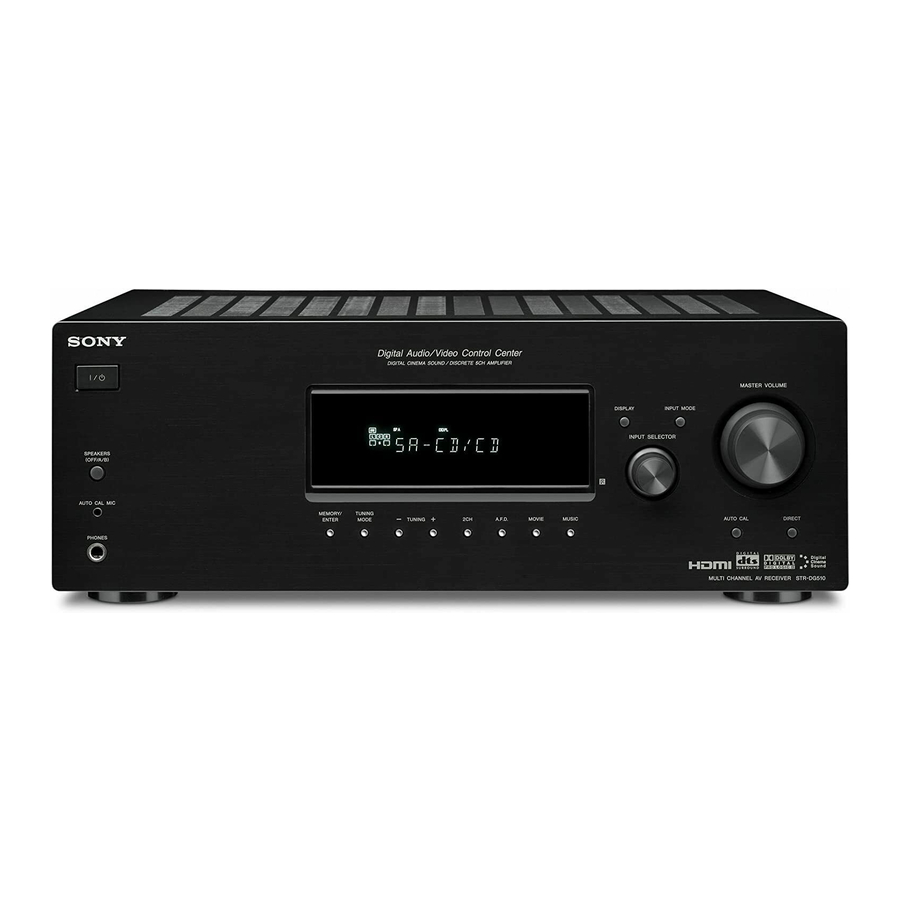
Page 6: Getting Started
Getting Started Description and location of parts Front panel SPEAKERS (OFF/A/B) AUTO CAL MIC PHONES Name Function A ?/1 Press to turn the receiver on (on/standby) or off (page 26, 34, 35, 52, 69). B SPEAKERS Press to select the front (OFF/A/B) speaker system (page 27). - Page 7 Name Function L MEMORY/ Press to operate the tuner ENTER (FM/AM) (page 52). TUNING MODE TUNING +/– M AUTO CAL Connects to the supplied MIC jack optimizer microphone for the Auto Calibration function (page 28). N PHONES jack Connects to headphones (page 64).
-
Page 8: About Indicators On Display
About the indicators on the display SP A SP B Name Function A SW Lights up when sub woofer selection is set to “YES” (page 42) and the audio signal is output from the SUB WOOFER jack. B LFE Lights up when the disc being played back contains an LFE (Low Frequency Effect) channel and the LFE channel... - Page 9 Name Function H MEMORY Lights up when a memory function, such as Preset Memory (page 55), etc., is activated. I Tuner Lights up when using the indicators receiver to tune in radio stations (page 52), etc. Note “RDS” appears for models of area code CEL, CEK only.
-
Page 10: Rear Panel
Rear panel OPTICAL DVD IN VIDEO 2 /BD IN HDMI VIDEO 2/ BD IN VIDEO IN VIDEO IN VIDEO OUT VIDEO IN VIDEO 1 COAXIAL DIGITAL ANTENNA AUDIO IN AUDIO IN AUDIO IN AUDIO OUT AUDIO IN SA-CD/CD VIDEO 1 A DIGITAL INPUT/OUTPUT section OPTICAL IN jacks... - Page 11 TV or projector (page 18, 20). Remote commander You can use the supplied remote RM-AAU013 to operate the receiver and to control the Sony audio/video components that the remote is assigned to operate (page 61). TV INPUT AUTO...
- Page 12 When you press any of the input buttons, the receiver turns on. The buttons are factory assigned to control Sony components as follows. You can change the button assignments following the steps in “Changing button assignments” on page 61.
- Page 13 Name Function Press to – search tracks in the forward/ reverse direction of the DVD player. – start fast forward/rewind of the VCR, CD player or blu- ray disc player. Press to start playback of the VCR, CD player, DVD player, or blu-ray disc player.
-
Page 14: 1: Installing Speakers
Name Function S -/-- Press -/-- and TV (M) at the same time to select the channel entry mode, either one or two digits of the TV. >10/ Press to select – track numbers over 10 of the VCR, satellite tuner or CD player. -
Page 15: 2: Connecting Speakers
2: Connecting speakers VIDEO 2 /BD IN HDMI SAT IN DVD IN MONITOR OUT VIDEO IN VIDEO IN VIDEO OUT VIDEO IN VIDEO OUT VIDEO 1 MONITOR COMPONENT VIDEO AUDIO OUT AUDIO OUT AUDIO IN AUDIO IN AUDIO IN WOOFER VIDEO 1 A Monaural audio cord (not supplied) B Speaker cords (not supplied) -
Page 16: 3A: Connecting The Audio Components
3a: Connecting the audio components Connecting a Super Audio CD/ CD player The following illustration shows how to connect a Super Audio CD/CD player. After connecting your Super Audio CD/CD player, proceed to “3b: Connecting the video components” (page 17). Super Audio CD player/CD player OPTICAL... -
Page 17: 3B: Connecting The Video Components
3b: Connecting the video components How to connect your components This section describes how to connect your video components to this receiver. Before you begin, refer to “Component to be connected” below for the pages which describe how to connect each component. After connecting all your components, proceed to “4: Connecting the antennas (aerials)”... -
Page 18: Connecting Components With Hdmi Jacks
ANTENNA AUDIO IN AUDIO IN SA-CD/CD A Coaxial digital cord (not supplied) B HDMI cable (not supplied) We recommend that you use a Sony HDMI cable. C Optical digital cord (not supplied) Blu-ray disc player Audio/video Audio signals signals VIDEO 2 /BD IN... - Page 19 Notes on HDMI connections • The sound is output from the TV speaker only when a playback component and this receiver, as well as this receiver and the TV are connected via the HDMI jack. To output the sound from the supplied speakers and to take advantage of the multi channel surround sound, be sure to –...
-
Page 20: Connecting A Tv
Connecting a TV The image from a video component connected to this receiver can be displayed on a TV screen. It is not necessary to connect all the cords. Connect audio and video cords according to the jacks of your components. Audio signals OPTICAL DVD IN... -
Page 21: Connecting A Dvd Player
Connecting a DVD player/DVD recorder The following illustration shows how to connect a DVD player/DVD recorder. It is not necessary to connect all the cords. Connect audio and video cords according to the jacks of your components. Connecting a DVD player DVD player Audio signals OPTICAL... -
Page 22: Connecting A Dvd Recorder
Connecting a DVD recorder Video signals OPTICAL DVD IN VIDEO 2 /BD IN HDMI VIDEO 2/ BD IN VIDEO IN VIDEO IN VIDEO OUT COAXIAL DIGITAL ANTENNA AUDIO IN AUDIO IN AUDIO IN AUDIO OUT SA-CD/CD A Video cord (not supplied) B Audio cord (not supplied) Notes •... - Page 23 Connecting a satellite tuner/ set-top box The following illustration shows how to connect a satellite tuner or a set-top box. It is not necessary to connect all the cords. Connect audio and video cords according to the jacks of your components. Satellite tuner/set-top box Audio signals OPTICAL...
-
Page 24: Connecting Components With
Connecting components with analog video and audio jack The following illustration shows how to connect a component which has analog jacks such as a VCR, etc. It is not necessary to connect all the cords. Connect audio and video cords according to the jacks of your components. -
Page 25: 4: Connecting The Antennas (Aerials)
4: Connecting the antennas (aerials) Connect the supplied AM loop antenna (aerial) and FM wire antenna (aerial). FM wire antenna (aerial) (supplied) OPTICAL DVD IN VIDEO 2 /BD IN HDMI VIDEO 2/ BD IN VIDEO IN VIDEO IN VIDEO OUT VIDEO 1 COAXIAL DIGITAL... -
Page 26: 5: Preparing The Receiver And The Remote
5: Preparing the receiver and the remote Setting the voltage selector If your receiver has a voltage selector on the rear panel, check that the voltage selector is set to the local power supply voltage. If not, use a screwdriver to set the selector to the correct position before connecting the AC power cord to a wall outlet. -
Page 27: Inserting Batteries Into Remote
Inserting batteries into the remote Insert two R6 (size-AA) batteries in the RM-AAU013 remote commander. Observe the correct polarity when installing batteries. Notes • Do not leave the remote in an extremely hot or humid place. • Do not use a new battery with old ones. •... -
Page 28: 7: Calibrating The Appropriate Settings Automatically (Auto Calibration)
7: Calibrating the appropriate settings automatically (AUTO CALIBRATION) The DCAC (Digital Cinema Auto Calibration) function allows you to perform automatic calibration such as: • Checking the connection between each speaker and the receiver. • Adjusting the speaker level. • Measuring the distance of each speaker from your listening position. -
Page 29: Performing Auto Calibration
Performing Auto Calibration TV INPUT AUTO TV ?/1 SLEEP AV ?/1 SYSTEM STANDBY VIDEO 1 VIDEO 2 VIDEO 3 SA-CD/CD TUNER A.F.D. MOVIE MUSIC AMP MENU FM MODE D.TUNING D.SKIP MEMORY DVD MENU >10/ 0/10 ENTER CLEAR MUTING DISPLAY TOOLS TV VOL MASTER VOL RETURN/EXIT... - Page 30 Error and warning codes When error codes appear When an error is detected during Auto Calibration, an error code will appear on the display cyclically after each measurement process as follows: Error code t blank display t (error code t blank display) t PUSH t blank display t ENTER...
-
Page 31: 8: Adjusting The Speaker Levels And Balance (Test Tone)
Warning codes and solutions Warning Explanation and solution code WARN. 40 The environment is noisy. Make sure the environment is quiet during Auto Calibration. WARN. 60 The front speaker balance is out of range. Reposition your front speakers. WARN. 62 The center speaker level is out of range. -
Page 32: Playback
Press V/v repeatedly to select “T. TONE Y”. The test tone is output from each speaker in sequence as follows: Front left t Center t Front right t Surround right t Surround left t Sub woofer Adjust the speaker levels and balance using the LEVEL menu so that the level of the test tone sounds the same from each... - Page 33 Selected input Components that can [Display] be played back VIDEO 1 VCR, etc., connected to [VIDEO 1] the VIDEO 1 jack VIDEO 2 Blu-ray disc player, etc., [VIDEO 2/BD]* connected to the VIDEO 2/BD jack DVD player, etc., [DVD] connected to DVD jack Satellite tuner, etc.
-
Page 34: Listening/Watching A Component
> TUNING – TUNING + Notes • The operation is described for a Sony Super Audio CD player. • Refer to the operating instructions supplied with the Super Audio CD player or CD player. You can select the sound field to suit the music. -
Page 35: Watching A Dvd
Watching a DVD TV INPUT AUTO TV ?/1 SLEEP AV ?/1 SYSTEM STANDBY VIDEO 1 VIDEO 2 VIDEO 3 SA-CD/CD TUNER A.F.D. MOVIE MUSIC AMP MENU FM MODE D.TUNING D.SKIP >10/ MEMORY DVD MENU 0/10 ENTER SPEAKERS CLEAR (OFF/A/B) DISPLAY TOOLS MUTING TV VOL... -
Page 36: Amplifier Operations
Amplifier Operations Navigating through menus By using the amplifier menus, you can make various adjustments to customize the receiver. A.F.D. MOVIE MEMORY DVD MENU >10/ 0/10 ENTER CLEAR DISPLAY TOOLS RETURN/EXIT MENU TV CH – PRESET – REPLAY ADVANCE < <... - Page 37 Overview of the menus The following options are available in each menu. For details on navigating through menus, see page 36. Menu Parameters [Display] [Display] LEVEL Test tone [T. TONE] [1-LEVEL] Front speaker balance (page 39) [FRT BAL] Center speaker level [CNT LVL] Surround left speaker level [SL LVL]...
- Page 38 Menu Parameters [Display] [Display] AUDIO Digital audio input decoding [5-AUDIO] priority [DEC. PRI.] (page 41) Digital broadcast language selection Synchronizes audio and video output [A.V. SYNC.] Naming inputs SYSTEM Sub woofer [6-SYSTEM] [SW SPK] (page 42) Front speakers [FRT SPK] Center speakers [CNT SPK] Surround speakers...
-
Page 39: Adjusting The Level (Level Menu)
Adjusting the level (LEVEL menu) You can use the LEVEL menu to adjust the balance and level of each speaker. These settings are applied to all sound fields. Select “1-LEVEL” in the amplifier menus. For details on adjusting the parameters, see “Navigating through menus”... -
Page 40: Adjusting The Tone (Tone Menu)
Adjusting the tone (TONE menu) You can use the TONE menu to adjust the tonal quality (bass/treble level) of the front speakers. These settings are applied to all sound fields. Select “2-TONE” in the amplifier menus. For details on adjusting the parameters, see “Navigating through menus”... -
Page 41: Settings For The Tuner (Tuner Menu)
Settings for the tuner (TUNER menu) You can use the TUNER menu to set the FM station receiving mode and to name preset stations. Select “4-TUNER” in the amplifier menus. For details on adjusting the parameters, see “Navigating through menus” (page 36) and “Overview of the menus”... -
Page 42: Settings For The System (System Menu)
x DUAL (Digital broadcast language selection) Lets you select the language you want to listen to during digital broadcast. This feature only functions for Dolby Digital sources. • DUAL M/S (Main/Sub) Sound of the main language will be output through the front left speaker and sound of the sub language will be output through the front right speaker simultaneously. - Page 43 x FRT SPK (Front speakers) • LARGE If you connect large speakers that will effectively reproduce bass frequencies, select “LARGE”. Normally, select “LARGE”. When the sub woofer is set to “NO”, the front speakers are automatically set to “LARGE”. • SMALL If the sound is distorted, or you feel a lack of surround effects when using multi channel surround sound, select “SMALL”...
-
Page 44: Speaker Distance
x FRT DIST. (Front speaker distance) Lets you set the distance from your listening position to the front speakers (A). If both front speakers are not placed an equal distance from your listening position, set the distance as the average distance between the front speakers. - Page 45 • SIDE/LO Select if the location of your surround speakers corresponds to sections A and C. • SIDE/HI Select if the location of your surround speakers corresponds to sections A and D. • BEHD/LO Select if the location of your surround speakers corresponds to sections B and C.
-
Page 46: Calibrating The Appropriate Settings Automatically (A. Cal Menu)
Calibrating the appropriate settings automatically (A. CAL menu) For details, see “7: Calibrating the appropriate settings automatically (AUTO CALIBRATION)” (page 28). Enjoying Surround Sound Enjoying Dolby Digital and DTS Surround sound (AUTO FORMAT DIRECT) The Auto Format Direct (A.F.D.) mode allows you to listen to higher fidelity sound and select the decoding mode for listening to a 2 channel stereo sound as multi channel sound. - Page 47 Types of A.F.D. mode Decoding A.F.D. mode mode [Display] (Detecting A.F.D. AUTO automatically) [A.F.D. AUTO] Dolby Pro Logic PRO LOGIC [DOLBY PL] Dolby Pro Logic PRO LOGIC II MOVIE [PLII MV] PRO LOGIC II MUSIC [PLII MS] (Multi Stereo) MULTI STEREO [MULTI ST.] Multi channel Effect...
-
Page 48: Selecting A Pre-Programmed Sound Field
If you connect a sub woofer This receiver will generate a low frequency signal for output to the sub woofer when there is no LFE signal, which is a low-pass sound effect output from a sub woofer to a 2 channel signal. - Page 49 * You can only select this sound field if the headphones are connected to the receiver. Effect Reproduces the sound characteristics of the Sony Pictures Entertainment “Cary Grant Theater” cinema production studio. This is a standard mode, great for watching almost any type of movie.
- Page 50 Sound fields with DC S mark use DCS technology. DCS is a unique sound reproduction technology for home theater developed by Sony, in cooperation with Sony Pictures Entertainment, for enjoying the exciting and powerful sound of movie theaters at home. With this “Digital Cinema Sound” developed...
-
Page 51: Using Only The Front Speakers (2Ch Stereo)
Using only the front speakers (2CH STEREO) In this mode, the receiver outputs the sound from the front left/right speakers only. There is no sound from the sub woofer. Standard 2 channel stereo sources completely bypass the sound field processing and multi channel surround formats are downmixed to 2 channel. -
Page 52: Resetting Sound Fields To The Initial Settings
Resetting sound fields to the initial settings Be sure to use the buttons on the receiver for this operation. SPEAKERS (OFF/A/B) AUTO CAL MIC MEMORY/ TUNING ENTER MODE TUNING A.F.D. MOVIE PHONES Press ?/1 to turn off the power. While holding down 2CH, press ?/1. -
Page 53: Direct Tuning
Automatic tuning VIDEO 1 VIDEO 2 VIDEO 3 SA-CD/CD TUNER A.F.D. MOVIE MUSIC AMP MENU FM MODE D.TUNING D.SKIP >10/ MEMORY DVD MENU 0/10 ENTER CLEAR DISPLAY TOOLS MUTING TV VOL MASTER VOL RETURN/EXIT MENU TV CH – TV CH + PRESET –... -
Page 54: Presetting Radio Stations
Press ENTER. You can also use MEMORY/ENTER on the receiver. If you cannot tune in a station Make sure you have entered the right frequency. If not, repeat steps 2 to 4. If you still cannot tune in a station, the frequency is not used in your area. -
Page 55: Tuning To Preset Stations
Press MEMORY. You can also use MEMORY/ENTER on the receiver. “MEMORY” lights up for a few seconds. Perform steps 4 and 5 before “MEMORY” goes out. Press the numeric buttons to select a preset number. You can also press PRESET + or PRESET –... -
Page 56: Naming Preset Stations
Naming preset stations VIDEO 1 VIDEO 2 VIDEO 3 SA-CD/CD TUNER A.F.D. MOVIE >10/ MEMORY DVD MENU 0/10 ENTER CLEAR DISPLAY TOOLS RETURN/EXIT MENU Press TUNER repeatedly to select the FM or AM band. You can also use INPUT SELECTOR on the receiver. -
Page 57: Using The Radio Data System (Rds)
Using the Radio Data System (RDS) (Models of area code CEL, CEK only) This receiver also allows you to use RDS (Radio Data System), which enables radio stations to send additional information along with the regular program signal. You can display RDS information. -
Page 58: Other Operations
Program type Description indication VARIED Other types of programs such as celebrity interviews, panel games, and comedy POP M Popular music programs ROCK M Rock music programs EASY M Easy Listening LIGHT M Instrumental, vocal, and choral music CLASSICS Performances of major orchestras, chamber music, opera, etc. -
Page 59: Naming Inputs
Naming inputs You can enter a name of up to 8 characters for inputs and display it on the receiver’s display. This is convenient for labeling the jacks with the names of the connected components. Press the input button to select the input you want to create an index name for. -
Page 60: Using The Sleep Timer
Using the Sleep Timer You can set the receiver to turn off automatically at a specified time. Press SLEEP repeatedly while the power is on. Each time you press the button, the display changes cyclically as follows: 1-30-00 t 1-00-00 t 0-30-00 2-00-00 t t OFF When sleep timer is activated, the display... -
Page 61: Using The Remote
(command mode BD1) Blu-ray disc recorder (command mode BD3) Not assigned Sony VCRs are operated with a VTR 2 or VTR 3 setting which corresponds to 8 mm and VHS respectively. Sony DVD recorders are operated with a DVD1 or DVD3 setting. -
Page 62: Additional Information
Additional Information Glossary x Component video A format for transmitting video signal information consisting of three separate signals: luminance Y, chrominance Pb, and chrominance Pr. High quality pictures, such as DVD video or HDTV pictures, are transmitted more faithfully. The three jacks are color - coded green, blue and red. -
Page 63: Precautions
Do not use any type of abrasive pad, scouring powder, or solvent, such as alcohol or benzine. If you have any questions or problems concerning your receiver, please consult your nearest Sony dealer. -
Page 64: Troubleshooting
Troubleshooting If you experience any of the following difficulties while using the receiver, use this troubleshooting guide to help you remedy the problem. Audio There is no sound, no matter which component is selected, or only a very low-level sound is heard. •... - Page 65 There is severe hum or noise. • Check that the speakers and components are connected securely. • Check that the connecting cords are away from a transformer or motor, and at least 3 m (10 feet) away from a TV set or fluorescent light.
-
Page 66: Error Messages
You can check the condition of the system by the message. Refer to the following table to solve the problem. If any problem persists, consult your nearest Sony dealer. If an error message appears while you perform Auto Calibration, see “Error and warning codes”... -
Page 67: Specifications
If the problem persist Consult your nearest Sony dealer. Note that if service personnel changes some parts during repair, these parts may be retained. Reference sections for clearing the receiver’s memory... - Page 68 Models of area code KR Minimum RMS Output Power (8 ohms, 20 Hz – 20 kHz, THD 0.09%) 85 W + 85 W 70 W + 70 W Stereo Mode Output Power (8 ohms, 1 kHz, THD 1%) 100 W + 100 W 90 W + 90 W Surround Mode Output Power THD 10%)
- Page 69 You can change the AM tuning scale to 9 kHz or 10 kHz. After tuning in any AM station, turn off the receiver. While holding down TUNING MODE, press ?/1. All preset stations will be erased when you change the tuning scale. To reset the scale to 10 kHz (or 9 kHz), repeat the procedure.
-
Page 70: Index
Index Numerics 2 channel 51 2CH STEREO 51 5.1 channel 14 AUTO CALIBRATION 28 AUTO FORMAT DIRECT (A.F.D.) 46 Blu-ray disc player connecting 18 CD player connecting 16 playback 34 Digital Cinema Sound (DCS) 50 Dolby Digital 62 DTS 62 DVD player connecting 21 playback 35... - Page 72 Sony Corporation Printed in Malaysia...