Table of Contents
Advertisement
Quick Links
•
•
•
•
Register your new swing set on-line @ www.swingsetsonline.com
Features the
Save this assembly manual for future reference in the event that
INS-6815-A-WOODRIDGE II-ENG-3-20-15
• Owner's Manual
• Frequently Asked Questions
• Assembly Instructions
• Warranty Information
(you will also find any updates on assembly instructions and
information to order replacement parts)
you need to order replacement parts.
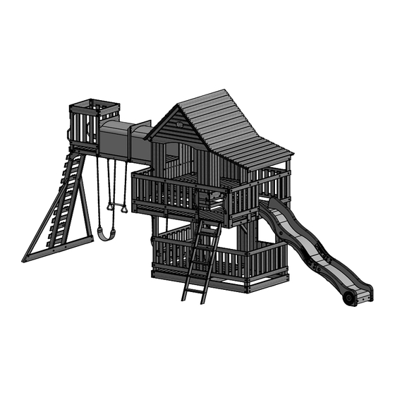
WOODRIDGE II
WOODEN PLAYSET
MODEL: #6815
fastening system.
Made in China
Advertisement
Table of Contents

Subscribe to Our Youtube Channel
Related Manuals for Backyard WOODRIDGE II


Summary of Contents for Backyard WOODRIDGE II
- Page 1 WOODRIDGE II WOODEN PLAYSET MODEL: #6815 • • Owner's Manual • • Frequently Asked Questions • • Assembly Instructions • • Warranty Information Register your new swing set on-line @ www.swingsetsonline.com (you will also find any updates on assembly instructions and...
- Page 2 STOP PARE Missing A Part? CALL US BEFORE GOING BACK TO THE STORE! The store where you made your purchase does not stock parts for this item. If you have assembly questions or if you need parts, whether they are missing or damaged Call Toll-Free Help Line or visit www.swingsetsonline.com ¡LLÁMENOS ANTES DE REGRESAR A LA TIENDA! La tienda donde realizó...
- Page 3 Owner’s Manual Play Set Dear Customer: Please read entire booklet completely before beginning the assembly process. Equipment is recommended for use by children 3 to 10 years of age. Structures are not intended for public use. The Company does not warranty any of its residential structures subjected to commercial use such as: Daycare, Preschool, Nursery School, Recreational Park, or any similar Commercial Application.
- Page 4 Owner’s Manual Play Set Please refer to the Assembly section of the Assembly Manual for Maximum Fall Height. Positioning Your Playcenter 1. The Playcenter is designed to be installed on a level surface by an Adult with an Adult helper. Place in a flat area of your yard to minimize ground preparation.
- Page 5 Owner’s Manual Play Set The following chart explains the fall height in feet from which a life threatening head injury would not be expected Critical Heights in feet (m) of Tested Materials Material Uncompressed Depth Compressed Depth 6" (152mm) 9" (228mm) 12" (304mm) to 9"...
- Page 6 Owner’s Manual Play Set 18. Verify that any suspended climbing ropes, chain, or cable are secured at both ends and that they cannot be looped back on it. 19. Instruct children not to attach items to the playground equipment that are not specifically designed for use with the equipment, such as, but not limited to, jump ropes, clothesline, pet leashes, cables and chain as they may cause a strangulation hazard.
- Page 7 Third Party Assembly: Customer may, in their sole discretion, elect to use a third party person or service to assemble this product. Backyard Discovery assumes no responsibility or liability for any charge incurred by the Customer for any assembly services’.
- Page 8 Owner’s Manual Play Set APPENDIX A Information on Playground Surfacing Materials: SECTION 4 OF THE CONSUMER PRODUCT SAFETY COMMISSION’S OUTDOOR HOME PLAYGROUND SAFETY HANDBOOK X3.1 Select Protective Surfacing—One of the most important things you can do to reduce the likelihood of serious head injuries is to install shock-absorbing protective surfacing under and around your play equipment.
- Page 9 5. How often should the playset be stained? Backyard Discovery recommends the playset be stained once each year. A water or oil based stain can be used at the customer’s discretion. 6. Why does it seem that my swing set is developing cracks? Wood is a natural material;...
- Page 10 Tools Required for Installation: (These are the tools that are generally required for assembly of our outdoor products. These tools are not included with the outdoor product purchase.) (Square) (Level 24") (Phillips Screw Driver) (Tape Measure) (Claw Hammer) (Rubber Mallet - Optional) (Drill Attachments: Phillips Head) (Ladder)
- Page 11 Basic Setup Dimensions Place the set on level ground, not less than 6 ft [2 m] from any structure or obstruction such as a fence, garage, house, overhanging branches, laundry lines, or electrical wires. Safe Play Zone 24'-8 1/2" [1.8] [7.5] 22'-1 1/2"...
- Page 12 Parts Identification Wood Components (NOT TO SCALE) B1 - SWING BEAM - W4L05729 3"x3"x89 1/2" (76x76x2274) B2 - SWING BEAM - W4L05750 3"x3"x89 1/2" (76x76x2274) B3 - POST - W4L05384 3"x3"x70 3/8" (76x76x1786) B4 - POST - W4L05608 3"x3"x70 3/8" (76x76x1786) B5 - POST - W4L05594 3"x3"x59"...
- Page 13 Parts Identification Wood Components (NOT TO SCALE) F4 - UPRIGHT - W4L05746 1 3/8"x2 3/8"x23 1/8" (36x60x586) F5 - BRACE - W4L05728 1 3/8"x2 3/8"x18 1/8" (36x60x460) G1 - GROUND BOARD - W4L05385 1"x5 1/4"x90 1/8" (24x134x2288) G2 - GROUND BOARD - W4L05731 1"x5 1/4"x89 1/2"...
- Page 14 Parts Identification Wood Components (NOT TO SCALE) H8 - FLOOR SUPPORT - W4L05624 1"x3 3/8"x53" (24x86x1346) H9 - FLOOR SUPPORT - W4L05625 1"x3 3/8"x53" (24x86x1346) H10 - SUPPORT BOARD - W4L05725 1"x3 3/8"x53" (24x86x1346) H11 - ROOF RAFTER - W4L05707 1"x3 3/8"x43 7/8"...
- Page 15 Parts Identification Wood Components (NOT TO SCALE) K4 - ARCHED RAIL - W4L05643 5/8"x5 1/4"x55 5/8" (16x134x1414) K5 - WALL RAIL - W4L05631 5/8"x5 1/4"x54 1/4" (16x134x1378) K6 - ARCHED RAIL - W4L05637 5/8"x5 1/4"x54 1/4" (16x134x1378) K7 - ARCHED RAIL - W4L05642 5/8"x5 1/4"x54 1/4"...
- Page 16 Parts Identification Wood Components (NOT TO SCALE) K93 - GABLE BOARD - W4L05716 3/8"x3 3/8"x36 7/8" (11x86x936) K94 - GABLE BOARD - W4L05717 3/8"x3 3/8"x30 1/2" (11x86x774) K95 - GABLE BOARD - W4L05718 3/8"x3 3/8"x24 1/8" (11x86x612) K96 - GABLE BOARD - W4L05719 3/8"x3 3/8"x17 3/4"...
- Page 17 Parts Identification Wood Components (NOT TO SCALE) L10 - WALL BOARD - W4L05614 5/8"x4 3/8"x23 3/4" (16x112x602) L11 - WALL BOARD - W4L05641 5/8"x4 3/8"x20 3/8" (16x112x518) L12 - CORNER BOARD - W4L05754 5/8"x4 3/8"x41 1/2" (16x112x1055) H20 - WALL RAIL - W4L05645 1"x3 3/8"x92"...
- Page 18 Parts Identification Wood Components (NOT TO SCALE) M15 - WALL BOARD - W4L05706 5/8"x3 3/8"x31" (16x86x788) M16 - WALL RAIL - W4L05748 5/8"x3 3/8"x27 3/4" (16x86x706) M17 - WALL RAIL - W4L05742 5/8"x3 3/8"x26 7/8" (16x86x682) M18 - FLOOR BOARD - W4L05607 (16) 5/8"x3 3/8"x24 3/4"...
- Page 19 Parts Identification Wood Components (NOT TO SCALE) M107 - ATTACHMENT BOARD - W103559 5/8"x3 3/8"x19 1/4" (16x86x488) N1 - WALL BOARD - W4L05751 5/8"x2 3/8"x32" (16x60x812) N2 - WINDOW TRIM - W4L05722 5/8"x2 3/8"x30" (16x60x761) N3 - WINDOW TRIM - W4L05615 5/8"x2 3/8"x22 1/2"...
- Page 20 Parts Identification Wood Components (NOT TO SCALE) (1) RP3 - PORCH PANEL - W2A01694 1 5/8"x20 5/8"x60 7/8" (42x524x1546) (1) RP4 - PORCH PANEL - W2A01695 1 5/8"x15 5/8"x60 7/8" (42x396x1546) (1) RP5 - ROOF PANEL - W2A01696 1 5/8"x15 5/8"x60 7/8" (42x396x1546) G7 - SEAT - W4L05755 1"x5 1/4"x49 7/8"...
- Page 21 Parts Identification Hardware (13) CF - WASHER LOCK INT 10x18 - H100107 (24) CG - WASHER LOCK INT 8x15 - H100108 (201) AC - WASHER LOCK EXT 8x19 - H100030 (24) D - NUT BARREL WH 5/16x7/8 - H100005 (19) CM - BOLT WH 5/16x1/2 - H100115 (24) AD - WASHER LOCK EXT 12x19 - H100031...
- Page 22 Parts Identification Hardware - T-40 TORX BIT - A100042 (22) AB - LAG SCREW WH 5/16x3 - H100029 - T-40 TORX WRENCH - A100041 AA - LAG SCREW WH 5/16x2 1/2 - H100028 (24) BE - T-NUT 1/4 - H100072 (50) Z - LAG SCREW WH 5/16x2 - H100027 (142)
- Page 23 Parts Identification Accessories (NOT TO SCALE) DD - TRIANGLE PLATE 105 5 HOLE - A100005 HP - MESH PANEL - A100012 DX - SLIDE BED 10' LIGHT GREEN - A100035 DP - SWING SEAT GREEN - A100027 TR - SLIDE RAIL 10' TOP RIGHT GREEN - A100033 DT - SLIDE RAIL 10' TOP LEFT GREEN - A100032 DW - SLIDE SUPPORT TUBE 21.34x505 - A100034 21.34 OD x 2.77 W x 505...
- Page 24 Parts Identification Accessories (NOT TO SCALE) DR - SLIDE RAIL 10' BOTTOM LEFT GREEN - A100030 DS - SLIDE RAIL 10' BOTTOM RIGHT GREEN - A100031 EF - CHAIN GREEN 57" - A100047 KN - CHAIN GREEN 31" - A100177 JV - HAND GRIP GREEN 816 c/c - A100134 FX - HAND GRIP METAL GREEN 381 c/c - A100118 HC - BYD ID TAG (LARGE) 2011 WITH AGES - A100164...
- Page 25 H76 - LADDER RUNG - W100611 H77 - LEFT UPRIGHT - W100972 1"x3 3/8"x18 1/8" (24x86x460) 1"x3 3/8"x64 3/8" (24x86x1634) 5 FOOT LADDER ASSEMBLY STEP 1 SCREW PFH (10) SCREW PFH 8x2...
- Page 26 H78 - RIGHT UPRIGHT - W100973 1"x3 3/8"x64 3/8" (24x86x1634) 5 FOOT LADDER ASSEMBLY STEP 2 SCREW PFH (10) SCREW PFH 8x2...
- Page 27 M73 - REAR SUPPORT - W100610 M107 - ATTACHMENT BOARD - W103559 5/8"x3 3/8"x19 1/4" (16x86x488) 5/8"x3 3/8"x19 1/4" (16x86x488) 5 FOOT LADDER ASSEMBLY STEP 3 M107 SCREW PFH SCREW PFH 8x2 FLUSH 1 1/4...
- Page 28 JV - HAND GRIP GREEN 816 c/c - A100134 5 FOOT LADDER ASSEMBLY STEP 4 LAG SCREW WH 1/4x1-1/2 LAG SCREW WH 1/4x1-1/2...
- Page 29 M70 - SLIDE BED SUPPORT - W100935 DX - SLIDE BED 10' LIGHT GREEN - A100035 5/8"x3 3/8"x19 7/8" (16x86x505) 10 FOOT SLIDE ASSEMBLY STEP 1 BOLT WH 5/16x1/2 T-NUT 5/16 DX - SLIDE BED 10' LIGHT GREEN (SEE SLIDE ASSEMBLY INSTALLATION STEP FOR DECK MOUNTING HOLE BOLT WH 5/16x1/2...
- Page 30 DS - SLIDE RAIL 10' BOTTOM RIGHT GREEN - A100031 TR - SLIDE RAIL 10' TOP RIGHT GREEN - A100033 DT - SLIDE RAIL 10' TOP LEFT GREEN - A100032 DR - SLIDE RAIL 10' BOTTOM LEFT GREEN - A100030 10 FOOT SLIDE ASSEMBLY STEP 2 BOLT WH...
- Page 31 DW - SLIDE SUPPORT TUBE 21.34x505 - A100034 21.34 OD x 2.77 W x 505 10 FOOT SLIDE ASSEMBLY STEP 3 PLACE (1) SLIDE RAIL ASSEMBLY ON A FLAT SURFACE AND BEGIN INSERTING SLIDE BED AT THE BOTTOM OF THE SLIDE RAIL (FIG. 1). HAVE A HELPER BEND THE SLIDE BED TOWARDS THE TOP OF THE SLIDE AND INSERT THE BED INTO THE SLIDE CAVITY.
- Page 32 10 FOOT SLIDE ASSEMBLY STEP 4 ONCE THE SLIDE BED, SUPPORT TUBES, AND SUPPORT BOARD ARE COMPLETELY IN THE CAVITY AND SUPPORT POCKET, SECURE USING 3" SCREWS AT EACH OF THE PILOT HOLE LOCATIONS AS SHOWN. REPEAT PROCESS FOR OPPOSITE SLIDE RAIL. SCREW PFH (38) SCREW PFH 8x3...
- Page 33 M2 - WALL RAIL - W4L05623 5/8"x3 3/8"x90 1/8" (16x86x2288) G1 - GROUND BOARD - W4L05385 1"x5 1/4"x90 1/8" (24x134x2288) B4 - POST - W4L05608 H7 - FLOOR SUPPORT - W4L05634 3"x3"x70 3/8" (76x76x1786) 1"x3 3/8"x53 3/4" (24x86x1366) B6 - POST - W4L05610 H5 - FLOOR SUPPORT - W4L05601 3"x3"x59"...
- Page 34 G1 - GROUND BOARD - W4L05385 1"x5 1/4"x90 1/8" (24x134x2288) K1 - DOUBLE ARCHED RAIL - W4L05611 5/8"x5 1/4"x90 1/8" (16x134x2288) B5 - POST - W4L05594 B3 - POST - W4L05384 3"x3"x59" (76x76x1500) 3"x3"x70 3/8" (76x76x1786) E4 - UPRIGHT - W4L05387 H5 - FLOOR SUPPORT - W4L05601 1 3/8"x3 3/8"x70 3/8"...
- Page 35 M8 - WALL RAIL - W4L05622 5/8"x3 3/8"x51 3/4" (16x86x1314) G4 - GROUND BOARD - W4L05390 1"x5 1/4"x53" (24x134x1346) STEP 3 LAG SCREW WH 5/16x2 WASHER LOCK EXT 8x19 FLUSH WASHER LOCK EXT 8x19 (8 PLCS) LAG SCREW WH 5/16x2 (8 PLCS)
- Page 36 M8 - WALL RAIL - W4L05622 5/8"x3 3/8"x51 3/4" (16x86x1314) H8 - FLOOR SUPPORT - W4L05624 1"x3 3/8"x53" (24x86x1346) G3 - GROUND BOARD - W4L05386 1"x5 1/4"x53" (24x134x1346) H2 - FLOOR SUPPORT - W4L05595 1"x3 3/8"x75 3/8" (24x86x1914) STEP 4 LAG SCREW NOTE HOLES WH 5/16x2...
- Page 37 G6 - FLOOR JOIST - W4L05389 1"x5 1/4"x49 1/2" (24x134x1256) G5 - GROUND BOARD - W4L05388 1"x5 1/4"x51 1/8" (24x134x1298) STEP 5 LAG SCREW WH 5/16x2 SCREW PFH 8x2 1/2 WASHER LOCK EXT 8x19 WASHER LOCK EXT 8x19 (4 PLCS) LAG SCREW WH 5/16x2 (4 PLCS) SCREW PFH 8x2 1/2...
- Page 38 Y1 - FLOOR BOARD - W4L05591 5/8"x4"x45 1/8" (16x102x1146) M5 - FLOOR BOARD - W4L05592 (14) 5/8"x3 3/8"x53" (16x86x1346) STEP 6 SCREW PFH (75) 8x1 1/2 14 PLCS SCREW PFH 8x1 1/2 (75 PLCS)
- Page 39 H4 - FLOOR SUPPORT - W4L05602 1"x3 3/8"x74 3/8" (24x86x1890) SQ - "A" REVISION TAG - A100314 STEP 7 LAG SCREW WH 5/16x2 WASHER LOCK EXT 8x19 "A" REVISION TAG SCREW PWH (1 PLC) 8x5/8 SCREW PWH 8x5/8 (2 PLCS) WASHER LOCK EXT 8x19 (2 PLCS) LAG SCREW WH 5/16x2...
- Page 40 H14 - FLOOR SUPPORT - W4L05603 1"x3 3/8"x35 3/8" (24x86x898) TZ - L BRACKET 2.5x38x50x55 - A100340 STEP 8 BOLT WH 5/16x3 3/4 WASHER LOCK EXT 8x19 (2 PLCS) NUT BARREL BOLT WH WH 5/16x7/8 5/16x1/2 BOLT WH 5/16x3 3/4 (2 PLCS) T-NUT 5/16 WASHER LOCK EXT 12x19...
- Page 41 H3 - FLOOR SUPPORT - W4L05606 1"x3 3/8"x75 3/8" (24x86x1914) H1 - FLOOR SUPPORT - W4L05593 1"x3 3/8"x90 1/8" (24x86x2288) STEP 9 BOLT WH 5/16x3 3/4 BOLT WH 5/16x2 1/4 T-NUT 5/16 WASHER LOCK EXT 8x19 BOLT WH 5/16x3 3/4 (3 PLCS) WASHER LOCK EXT 8x19 (5 PLCS)
- Page 42 L12 - CORNER BOARD - W4L05754 5/8"x4 3/8"x41 1/2" (16x112x1055) L7 - CORNER BOARD - W4L05597 5/8"x4 3/8"x31" (16x112x788) STEP 10 BOLT WH 5/16x4 1/2 T-NUT 5/16 (3 PLCS) WASHER T-NUT 5/16 LOCK EXT 8x19 WASHER LOCK EXT 8x19 (3 PLCS) BOLT WH 5/16x4 1/2 NOTE HOLES (3 PLCS)
- Page 43 E1 - FLOOR SUPPORT - W4L05596 L8 - CORNER BOARD - W4L05599 1 3/8"x3 3/8"x92" (36x86x2336) 5/8"x4 3/8"x31" (16x112x788) L9 - CORNER BOARD - W4L05600 THIS HOLE L6 - CORNER BOARD - W4L05647 5/8"x4 3/8"x31" (16x112x788) TOWARDS 5/8"x4 3/8"x31" (16x112x788) TZ - L BRACKET 2.5x38x50x55 - A100340 BOTTOM NUT BARREL WH 5/16x7/8...
- Page 44 H15 - FLOOR JOIST - W4L05605 1"x3 3/8"x35 3/8" (24x86x898) STEP 12 SCREW PFH 8x2 1/2 SCREW PFH 8x2 1/2 (8 PLCS)
- Page 45 F5 - BRACE - W4L05728 1 3/8"x2 3/8"x18 1/8" (36x60x460) STEP 13 BOLT WH 5/16x2 1/4 T-NUT 5/16 LAG SCREW WH 5/16x2 WASHER LOCK EXT 8x19 BOLT WH 5/16x2 1/4 (4 PLCS) T-NUT 5/16 (4 PLCS) LAG SCREW WH 5/16x2 (4 PLCS) WASHER LOCK EXT 8x19 (8 PLCS)
- Page 46 M4 - FLOOR BOARD - W4L05604 (11) 5/8"x3 3/8"x76 3/4" (16x86x1950) STEP 14 SCREW PFH (77) 8x1 1/2 11 PLCS SCREW PFH 8x1 1/2 (77 PLCS)
- Page 47 M18 - FLOOR BOARD - W4L05607 (16) 5/8"x3 3/8"x24 3/4" (16x86x628) STEP 15 SCREW PFH (64) 8x1 1/2 16 PLCS SCREW PFH 8x1 1/2 (64 PLCS)
- Page 48 H6 - FLOOR JOIST - W4L05626 H9 - FLOOR SUPPORT - W4L05625 1"x3 3/8"x53 3/4" (24x86x1366) 1"x3 3/8"x53" (24x86x1346) STEP 16 BOLT WH 5/16x4-1/4 SCREW PFH 8x2 1/2 WASHER T-NUT 5/16 LOCK EXT 8x19 SCREW PFH 8x2 1/2 (8 PLCS) BOLT WH 5/16x4-1/4 (2 PLCS) WASHER LOCK EXT 8x19...
- Page 49 M6 - FLOOR BOARD - W4L05627 (16) 5/8"x3 3/8"x53" (16x86x1346) STEP 17 SCREW PFH (96) 8x1 1/2 SCREW PFH 8x1 1/2 (96 PLCS) 16 PLCS...
- Page 50 M8 - WALL RAIL - W4L05622 5/8"x3 3/8"x51 3/4" (16x86x1314) M2 - WALL RAIL - W4L05623 5/8"x3 3/8"x90 1/8" (16x86x2288) STEP 18 LAG SCREW WH 5/16x2 T-NUT 5/16 BOLT WH 5/16x2 WASHER LOCK EXT 8x19 FLUSH BOLT WH 5/16x2 (1 PLC) LAG SCREW WH 5/16x2 T-NUT 5/16 (4 PLCS)
- Page 51 M10 - WALL BOARD - W4L05618 M27 - WALL RAIL - W4L05753 5/8"x3 3/8"x41 1/8" (16x86x1044) 5/8"x3 3/8"x10 3/4" (16x86x274) M26 - WALL RAIL - W4L05619 L4 - WALL BOARD - W4L05617 5/8"x3 3/8"x11 1/8" (16x86x284) 5/8"x4 3/8"x41 1/8" (16x112x1044) STEP 19 BOLT WH 5/16x3 1/2...
- Page 52 L2 - WALL BOARD - W4L05612 5/8"x4 3/8"x45 1/8" (16x112x1146) L10 - WALL BOARD - W4L05614 5/8"x4 3/8"x23 3/4" (16x112x602) M9 - WALL BOARD - W4L05613 5/8"x3 3/8"x45 1/8" (16x86x1146) STEP 20 SCREW PFH (24) 8x1 1/8 3 11/16 SCREW PFH 8x1 1/8 (24 PLCS)
- Page 53 N4 - WINDOW TRIM - W4L05616 5/8"x2 3/8"x19 7/8" (16x60x504) N3 - WINDOW TRIM - W4L05615 5/8"x2 3/8"x22 1/2" (16x60x570) STEP 21 SCREW PFH (16) 8x1 1/8 SCREW PFH 8x1 1/8 (16 PLCS)
- Page 54 M49 - PICKET - 53 - W4L05374 (14) 5/8"x3 3/8"x20 3/8" (16x86x518) STEP 22 2 11/16 TYPICAL SPACING SCREW PFH (56) 8x1 1/8 1 13/16 14 PLCS SCREW PFH 8x1 1/8 (56 PLCS)
- Page 55 M49 - PICKET - 53 - W4L05374 5/8"x3 3/8"x20 3/8" (16x86x518) STEP 23 2 15/16 TYPICAL SPACING SCREW PFH (28) 8x1 1/8 1 13/16 SCREW PFH 8x1 1/8 (28 PLCS) 7 PLCS...
- Page 56 M49 - PICKET - 53 - W4L05374 5/8"x3 3/8"x20 3/8" (16x86x518) STEP 24 2 3/4 TYPICAL SPACING SCREW PFH (20) 8x1 1/8 1 13/16 5 PLCS SCREW PFH 8x1 1/8 (20 PLCS)
- Page 57 K13 - WALL RAIL - W4L05633 K14 - WALL RAIL - W4L05630 K15 - WALL RAIL - W4L05629 5/8"x5 1/4"x14 1/8" (16x134x360) 5/8"x5 1/4"x11 5/8" (16x134x294) 5/8"x5 1/4"x11 5/8" (16x134x294) STEP 25 BOLT WH 5/16x4 1/2 T-NUT 5/16 BOLT WH 5/16x3 WASHER LOCK EXT...
- Page 58 K5 - WALL RAIL - W4L05631 5/8"x5 1/4"x54 1/4" (16x134x1378) K2 - WALL RAIL - W4L05628 5/8"x5 1/4"x55 5/8" (16x134x1414) STEP 26 BOLT WH 5/16x4 1/2 T-NUT 5/16 BOLT WH 5/16x3 WASHER LOCK EXT BOLT WH 8x19 5/16x1 1/2 T-NUT 5/16 TYPICAL INSTALATION (4 PLCS) BOLT WH 5/16x1 1/2...
- Page 59 E6 - UPRIGHT - W4L05632 1 3/8"x3 3/8"x41" (36x86x1040) E7 - UPRIGHT - W4L05726 1 3/8"x3 3/8"x41" (36x86x1040) STEP 27 BOLT WH T-NUT 5/16 5/16x2 LAG SCREW WASHER WH 5/16x2 LOCK EXT 8x19 WASHER LOCK EXT 8x19 (8 PLCS) BOLT WH 5/16x2 LAG SCREW WH 5/16x2 (4 PLCS) (4 PLCS)
- Page 60 K6 - ARCHED RAIL - W4L05637 K7 - ARCHED RAIL - W4L05642 5/8"x5 1/4"x54 1/4" (16x134x1378) 5/8"x5 1/4"x54 1/4" (16x134x1378) K4 - ARCHED RAIL - W4L05643 K3 - ARCHED RAIL - W4L05640 5/8"x5 1/4"x55 5/8" (16x134x1414) 5/8"x5 1/4"x55 5/8" (16x134x1414) TZ - L BRACKET 2.5x38x50x55 - A100340 STEP 28 BOLT WH...
- Page 61 M12 - WALL BOARD - W4L05727 5/8"x3 3/8"x36" (16x86x914) M25 - WALL BOARD - W4L05724 5/8"x3 3/8"x14 1/4" (16x86x362) L5 - WALL BOARD - W4L05639 5/8"x4 3/8"x36" (16x112x914) STEP 29 SCREW PFH (42) 8x1 1/8 1 1/4 SCREW PFH 8x1 1/8 (42 PLCS) 5 PLCS...
-
Page 62: Table Of Contents
H10 - SUPPORT BOARD - W4L05725 TZ - L BRACKET 2.5x38x50x55 - A100340 1"x3 3/8"x53" (24x86x1346) STEP 30 BOLT WH T-NUT 5/16 5/16x2 1/4 WASHER LOCK EXT SCREW PFH (13) 8x19 BOLT WH 8x1 1/8 5/16x1 1/2 FLUSH SCREW PFH 8x1 1/8 T-NUT 5/16 BOLT WH 5/16x1 1/2 (13 PLCS) - Page 63 M13 - WALL BOARD - W4L05638 5/8"x3 3/8"x36" (16x86x914) STEP 31 SCREW PFH (24) 8x1 1/8 SCREW PFH 8x1 1/8 1 1/4 (24 PLCS) 6 PLCS...
- Page 64 M49 - PICKET - 53 - W4L05374 M13 - WALL BOARD - W4L05638 L11 - WALL BOARD - W4L05641 5/8"x3 3/8"x20 3/8" (16x86x518) 5/8"x3 3/8"x36" (16x86x914) 5/8"x4 3/8"x20 3/8" (16x112x518) STEP 32 SCREW PFH (46) 8x1 1/8 1 1/4 SCREW PFH 8x1 1/8 (46 PLCS) M49 6 PLCS...
- Page 65 N2 - WINDOW TRIM - W4L05722 5/8"x2 3/8"x30" (16x60x761) N5 - WINDOW TRIM - W4L05723 5/8"x2 3/8"x14" (16x60x356) STEP 33 1 3/16 1 3/16 SCREW PFH (20) 4 13/16 8x1 1/8 7 9/16 3 11/16 NOTE: DRILL 1/8" (5mm) HOLES WHERE INDICATED. SCREW PFH 8x1 1/8 (20 PLCS)
- Page 66 M13 - WALL BOARD - W4L05638 5/8"x3 3/8"x36" (16x86x914) STEP 34 SCREW PFH (24) 8x1 1/8 1 1/4 SCREW PFH 8x1 1/8 (24 PLCS) M13 6 PLCS...
-
Page 67: Bolt Wh 5/16X1 1/4
H17 - WALL RAIL - W4L05636 1"x3 3/8"x23 3/4" (24x86x604) TZ - L BRACKET 2.5x38x50x55 - A100340 H16 - WALL RAIL - W4L05635 1"x3 3/8"x26 1/4" (24x86x668) STEP 35 SCREW PFH 8x2 1/2 T-NUT 5/16 NUT BARREL BOLT WH WH 5/16x7/8 5/16x1 1/4 BOLT WH 5/16x1 1/2... - Page 68 M49 - PICKET - 53 - W4L05374 5/8"x3 3/8"x20 3/8" (16x86x518) STEP 36 2 7/16 TYPICAL SPACING SCREW PFH (12) 8x1 1/8 1 13/16 SCREW PFH 8x1 1/8 (12 PLCS) 3 PLCS...
-
Page 69: Washer Lock Ext 8X19 (2 Plcs)
H20 - WALL RAIL - W4L05645 M14 - WALL BOARD - W4L05644 1"x3 3/8"x92" (24x86x2336) 5/8"x3 3/8"x31" (16x86x788) M7 - WALL RAIL - W4L05646 M15 - WALL BOARD - W4L05706 5/8"x3 3/8"x63 1/4" (16x86x1608) 5/8"x3 3/8"x31" (16x86x788) TZ - L BRACKET 2.5x38x50x55 - A100340 STEP 37 BOLT WH BOLT WH... -
Page 70: Screw Pfh 8X1
M49 - PICKET - 53 - W4L05374 5/8"x3 3/8"x20 3/8" (16x86x518) STEP 38 2 1/2 TYPICAL SPACING SCREW PFH (32) 8x1 1/8 1 13/16 SCREW PFH 8x1 1/8 (32 PLCS) 8 PLCS... -
Page 71: Bolt Wh (2) 5/16X1
H13 - WALL RAIL - W4L05649 1"x3 3/8"x36 1/4" (24x86x922) TZ - L BRACKET 2.5x38x50x55 - A100340 H12 - WALL RAIL - W4L05648 1"x3 3/8"x38 3/4" (24x86x983) STEP 39 BOLT WH NUT BARREL 5/16x1 1/2 WASHER WH 5/16x7/8 LOCK EXT 8x19 T-NUT 5/16 BOLT WH... -
Page 72: Screw Pfh 8X1
M49 - PICKET - 53 - W4L05374 5/8"x3 3/8"x20 3/8" (16x86x518) STEP 40 2 1/2 TYPICAL SPACING SCREW PFH (20) 8x1 1/8 1 13/16 SCREW PFH 8x1 1/8 (20 PLCS) M49 5 PLCS... - Page 73 M3 - WALL RAIL - W4L05701 L3 - CORNER BOARD - W4L05598 5/8"x3 3/8"x78" (16x86x1982) 5/8"x4 3/8"x41 1/2" (16x112x1055) M14 - WALL BOARD - W4L05644 M24 - WALL RAIL - W4L05703 M11 - WALL RAIL - W4L05702 5/8"x3 3/8"x31" (16x86x788) 5/8"x3 3/8"x16"...
- Page 74 M49 - PICKET - 53 - W4L05374 5/8"x3 3/8"x20 3/8" (16x86x518) STEP 42 SCREW PFH (20) 8x1 1/8 2 3/8 1 1/2 2 5/16 TYPICAL SPACING 1 13/16 SCREW PFH 8x1 1/8 (20 PLCS) M49 5 PLCS...
- Page 75 N7 - SAFETY RAIL - W4L05709 N8 - SAFETY RAIL - W4L05705 5/8"x2 3/8"x53 3/4" (16x60x1366) 5/8"x2 3/8"x52 1/4" (16x60x1326) N9 - SAFETY RAIL - W4L05708 N10 - SAFETY RAIL - W4L05704 5/8"x2 3/8"x51 3/4" (16x60x1314) 5/8"x2 3/8"x50 1/8" (16x60x1274) STEP 43 SCREW PFH 8x1 1/2...
- Page 76 H11 - ROOF RAFTER - W4L05707 1"x3 3/8"x43 7/8" (24x86x1114) STEP 44 SCREW PFH 1 11/16 PRE-DRILL 1/8" (3mm) HOLE LAG SCREW WH 5/16x3 WASHER LOCK EXT 8x19 SCREW PFH 8x3 (2 PLCS) H11 4 PLCS WASHER LOCK EXT 8x19 (4 PLCS) LAG SCREW WH 5/16x3 (4 PLCS)
- Page 77 (1) RP1 - PEAK ROOF PANEL - W2A01692 (1) RP2 - ROOF PANEL - W2A01693 1 5/8"x15 5/8"x60 7/8" (42x396x1546) 1 5/8"x15 5/8"x60 7/8" (42x396x1546) (1) RP5 - ROOF PANEL - W2A01696 1 5/8"x15 5/8"x60 7/8" (42x396x1546) STEP 45 SCREW PFH (12) 8x2 1/2 SCREW PFH 8x2 1/2...
- Page 78 (1) RP1 - PEAK ROOF PANEL - W2A01692 (2) RP2 - ROOF PANEL - W2A01693 1 5/8"x15 5/8"x60 7/8" (42x396x1546) 1 5/8"x15 5/8"x60 7/8" (42x396x1546) STEP 46 SCREW PFH (12) 8x2 1/2 SCREW PFH 8x2 1/2 (12 PLCS)
- Page 79 O5 - CLEAT - W4L05712 5/8"x1 3/8"x36 7/8" (16x34x936) STEP 47 3 1/16 SCREW PFH (16) 8x1 1/8 3 1/16 SCREW PFH 8x1 1/8 (16 PLCS)
- Page 80 K91 - GABLE BOARD - W4L05714 K94 - GABLE BOARD - W4L05717 3/8"x3 3/8"x49 5/8" (11x86x1260) 3/8"x3 3/8"x30 1/2" (11x86x774) K97 - GABLE BOARD - W4L05720 3/8"x3 3/8"x11 3/8" (11x86x288) K95 - GABLE BOARD - W4L05718 K92 - GABLE BOARD - W4L05715 3/8"x3 3/8"x24 1/8"...
- Page 81 N1 - WALL BOARD - W4L05751 5/8"x2 3/8"x32" (16x60x812) HC - BYD ID TAG (LARGE) 2011 WITH AGES - A100164 HP - MESH PANEL - A100012 STEP 49 SCREW PFH 8x1 1/8 SCREW PFH (3 PLCS) 8x1 1/8 SCREW PWH 8x5/8 (6 PLCS) SCREW PWH 8x5/8...
- Page 82 J1 - PORCH RAFTER - W4L05710 L1 - WALL BOARD - W4L05711 1"x2 3/8"x38 1/4" (24x60x971) 5/8"x4 3/8"x54 1/4" (16x112x1378) STEP 50 BOLT WH NUT BARREL WASHER WASHER 5/16x1 1/4 WH 5/16x7/8 LOCK EXT LOCK EXT 8x19 12x19 SCREW PFH 8x2 1/2 T-NUT 5/16 BOLT WH...
- Page 83 (1) RP4 - PORCH PANEL - W2A01695 1 5/8"x15 5/8"x60 7/8" (42x396x1546) (1) RP3 - PORCH PANEL - W2A01694 1 5/8"x20 5/8"x60 7/8" (42x524x1546) O6 - CLEAT - W4L05713 5/8"x1 3/8"x26 3/4" (16x34x680) STEP 51 SCREW PFH 8x1 1/8 SCREW PFH (10) 8x2 1/2 3 3/8...
- Page 84 E2 - LADDER RAIL - W4L05730 M23 - LADDER RUNG - W4L05733 1 3/8"x3 3/8"x89 1/4" (36x86x2266) 5/8"x3 3/8"x16 7/8" (16x86x429) M21 - LADDER RUNG - W4L05735 M22 - LADDER RUNG - W4L05734 (11) 5/8"x3 3/8"x22 1/2" (16x86x572) 5/8"x3 3/8"x22 1/2" (16x86x572) STEP 52 SCREW PFH (52)
- Page 85 - GREEN HC ROCK #2 - A6P00037 - GREEN HC ROCK #1 - A6P00036 STEP 53 BOLT PTH (22) 1/4x3/4 WASHER (22) LOCK INT 8x15 (22) T-NUT 1/4 GREEN HC ROCK #2 (5 PLCS) GREEN HC ROCK #1 (6 PLCS) BOLT PTH 1/4x3/4 (22 PLCS) WASHER LOCK INT 8x15...
- Page 86 E3 - BRACE - W4L05732 1 3/8"x3 3/8"x72 5/8" (36x86x1845) G2 - GROUND BOARD - W4L05731 1"x5 1/4"x89 1/2" (24x134x2274) STEP 54 BOLT WH 5/16x3 WASHER LOCK EXT 8x19 BOLT WH 5/16x2 1/4 T-NUT 5/16 LAG SCREW WH 5/16x2 1/2 BOLT WH 5/16x3 (2 PLCS) BOLT WH 5/16x2 1/4...
- Page 87 B1 - SWING BEAM - W4L05729 3"x3"x89 1/2" (76x76x2274) B2 - SWING BEAM - W4L05750 3"x3"x89 1/2" (76x76x2274) DD - TRIANGLE PLATE 105 5 HOLE - A100005 STEP 55 BOLT WH 5/16x4 1/2 T-NUT 5/16 WASHER BOLT WH BOLT WH 5/16x2 1/2 5/16x2 1/2 LOCK EXT (4 PLCS)
- Page 88 (6) SWING HANGER - A4M00505 STEP 56 BOLT HEX (12) 3/8x3 1/4 T-NUT 3/8 (12) T-NUT 3/8 (12 PLCS) WASHER (12) FLAT 11x25 WASHER (12) LOCK INT 10x18 SWING HANGER (6 PLCS) WASHER FLAT 11x25 (12 PLCS) WASHER LOCK INT 10x18 (12 PLCS) BOLT HEX 3/8x3 1/4 (12 PLCS)
- Page 89 STEP 57 LAG SCREW WH 5/16x2 LAG SCREW WH 5/16x2 (2 PLCS)
- Page 90 M19 - FLOOR BOARD - W4L05738 M20 - FLOOR BOARD - W4L05737 (24) K12 - FLOOR BOARD - W4L05736 5/8"x3 3/8"x23 1/8" (16x86x586) 5/8"x3 3/8"x23 1/8" (16x86x586) 5/8"x5 1/4"x23 1/8" (16x134x586) STEP 58 SCREW PFH (104) 24 PLCS SCREW PFH 8x2 (104 PLCS)
- Page 91 F4 - UPRIGHT - W4L05746 1 3/8"x2 3/8"x23 1/8" (36x60x586) STEP 59 LAG SCREW WH 5/16x3 3 11/16 3 11/16 SCREW PFH 6 7/8 WASHER LOCK EXT 6 5/16 8x19 SCREW PFH 8x2 (4 PLCS) 2 PLCS WASHER LOCK EXT 8x19 (4 PLCS) LAG SCREW WH 5/16x3 (4 PLCS)
- Page 92 F2 - UPRIGHT - W4L05743 F3 - UPRIGHT - W4L05747 1 3/8"x2 3/8"x37" (36x60x940) 1 3/8"x2 3/8"x28 1/4" (36x60x716) STEP 60 LAG SCREW WH 5/16x3 WASHER LOCK EXT 8x19 WASHER LOCK EXT 8x19 (8 PLCS) LAG SCREW WH 5/16x3 (8 PLCS) LEAVE LOOSE AT THIS TIME FOR PLASTIC TUNNEL TO BE INSTALLED LATER...
- Page 93 K8 - WALL RAIL - W4L05741 K10 - ARCHED RAIL - W4L05745 5/8"x5 1/4"x27 1/8" (16x134x690) 5/8"x5 1/4"x25 7/8" (16x134x658) STEP 61 SCREW PFH LAG SCREW WH 5/16x2 SCREW PFH 8x1 1/2 WASHER T-NUT 5/16 LOCK EXT 8x19 WASHER LOCK EXT 8x19 (4 PLCS) LAG SCREW WH 5/16x2 (4 PLCS)
- Page 94 - TUNNEL - A6P00065 1/8"x61 3/8"x81" (2x1558x1649) STEP 62 SCREW PFH 8x1 1/2 1 7/8 TIGHTEN TIGHTEN TIGHTEN SCREW PFH 8x1 1/2 (6 PLCS) 1 3/16 TUNNEL 3 1/8 (1 PLC) 3 1/8...
- Page 95 N6 - WALL BOARD - W4L05749 M16 - WALL RAIL - W4L05748 5/8"x2 3/8"x10 3/8" (16x60x264) 5/8"x3 3/8"x27 3/4" (16x86x706) STEP 63 SCREW PFH 8x1 1/2 SCREW PFH (12) SCREW PFH 8x1 1/2 (4 PLCS) SCREW PFH 8x2 (12 PLCS) M16 4 PLCS...
- Page 96 F1 - UPRIGHT - W4L05739 1 3/8"x2 3/8"x37" (36x60x940) K9 - WALL RAIL - W4L05740 5/8"x5 1/4"x26 7/8" (16x134x682) STEP 64 LAG SCREW WH 5/16x3 T-NUT 5/16 WASHER (12) LOCK EXT BOLT WH 8x19 5/16x2 T-NUT 5/16 (8 PLCS) WASHER LOCK EXT 8x19 (12 PLCS) BOLT WH 5/16x2 (8 PLCS)
- Page 97 K11 - ARCHED RAIL - W4L05744 5/8"x5 1/4"x25 7/8" (16x134x658) K8 - WALL RAIL - W4L05741 5/8"x5 1/4"x27 1/8" (16x134x690) M17 - WALL RAIL - W4L05742 5/8"x3 3/8"x26 7/8" (16x86x682) STEP 65 LAG SCREW WH 5/16x2 WASHER T-NUT 5/16 LOCK EXT 8x19 BOLT WH SCREW PFH...
- Page 98 FX - HAND GRIP METAL GREEN 381 c/c - A100118 STEP 66 LAG SCREW WH 5/16x1 1/2 HAND GRIP METAL GREEN 381 c/c (2 PLCS) LAG SCREW WH 5/16x1 1/2 (4 PLCS)
- Page 99 M47 - PICKET - 51 - W4L05620 5/8"x3 3/8"x25 1/4" (16x86x640) STEP 67 EQUALLY SPACED SCREW PFH (24) 8x1 1/8 1 13/16 SCREW PFH 8x1 1/8 (24 PLCS) 6 PLCS...
- Page 100 EF - CHAIN GREEN 57" - A100047 KN - CHAIN GREEN 31" - A100177 DP - SWING SEAT GREEN - A100027 - TRAPEZE - A6P00034 FA - QUICK LINK - A100069 STEP 68 CHAIN GREEN 31" (2 PLCS) TRAPEZE (2 PLCS) CHAIN GREEN 57"...
- Page 101 FX - HAND GRIP METAL GREEN 381 c/c - A100118 STEP 69 BOLT WH 5/16x1/2 T-NUT 5/16 T-NUT 5/16 (4 PLCS) BOLT WH 5/16x1/2 (4 PLCS) HAND GRIP METAL GREEN 381 c/c (2 PLCS)
- Page 102 LADDER ASSEMBLY STEP 70 BOLT WH 5/16x2 WASHER T-NUT 5/16 LOCK EXT 8x19 T-NUT 5/16 (2 PLCS) WASHER LOCK EXT 8x19 (2 PLCS) BOLT WH 5/16x2 (2 PLCS) LADDER ASSEMBLY...
- Page 103 SLIDE ASSEMBLY STEP 71 4 1/16 BOLT WH 5/16x1/2 T-NUT 5/16 6 13/16 BOLT WH 5/16x1/2 (3 PLCS) SLIDE ASSEMBLY T-NUT 5/16 (3 PLCS)
- Page 104 H18 - SEAT - W4L05756 H19 - SUPPORT BOARD - W4L05757 1"x3 3/8"x49 7/8" (24x86x1266) 1"x3 3/8"x5 1/4" (24x86x132) M28 - CLEAT - W4L05758 G7 - SEAT - W4L05755 5/8"x3 3/8"x5 1/4" (16x86x132) 1"x5 1/4"x49 7/8" (24x134x1266) STEP 72 5 5/8 7 1/4 NOTE: SCREW PFH...
- Page 105 K16 - SAFETY RAIL - W4L05759 5/8"x5 1/4"x16 7/8" (16x134x430) STEP 73 SCREW PFH 8x1 1/8 SCREW PFH 8x1 1/8 (3 PLCS)
- Page 106 - GROUND STAKE REBAR - A4M00527 STEP 74 LAG SCREW WH 5/16x1 1/2 LAG SCREW (6 PLCS) WH 5/16x1 1/2 GROUND STAKE REBAR (6 PLCS) NOTE: FAILURE TO USE GROUND STAKES CAN VOID TYPICAL GROUND STAKE INSTALLATION WARRANTY AND CAUSE INJURY! (SEE BELOW) FINAL STEP DOUBLE CHECK EVERY BOLT, SCREW AND NUT FOR TIGHTNESS.
- Page 107 Limited Warranty. In addition, Backyard Discovery will replace any parts within the first 30 days from date of purchase found to be missing from or damaged in the original packaging.
Need help?
Do you have a question about the WOODRIDGE II and is the answer not in the manual?
Questions and answers