Table of Contents
Advertisement
Quick Links
OPERATOR'S MANUAL
BATTERY CHARGER POWER SUPPLY WITH RELAY ALARM SIGNALS
KEPCO INC.
An ISO 9001 Company.
IMPORTANT NOTES:
1)
This manual is valid for the following Model and associated serial numbers:
MODEL
2)
A Change Page may be included at the end of the manual. All applicable changes and
revision number changes are documented with reference to the equipment serial num-
bers. Before using this Instruction Manual, check your equipment serial number to identify
your model. If in doubt, contact your nearest Kepco Representative, or the Kepco Docu-
mentation Office in New York, (718) 461-7000, requesting the correct revision for your par-
ticular model and serial number.
3)
The contents of this manual are protected by copyright. Reproduction of any part can be
made only with the specific written permission of Kepco, Inc.
Data subject to change without notice.
©2019, KEPCO, INC
P/N 243-1400
KEPCO, INC. 131-38 SANFORD AVENUE FLUSHING, NY. 11355 U.S.A. TEL (718) 461-7000 FAX (718) 767-1102
TBC SERIES
POWER SUPPLY
MODEL
TBC SERIES
POWER SUPPLY
ORDER NO.
SERIAL NO.
email: hq@kepcopower.com World Wide Web: www.kepcopower.com
REV. NO.
REV. NO.
KEPCO
THE POWER SUPPLIER™
®
Advertisement
Table of Contents

Related Manuals for KEPCO TBC 12-50M


Summary of Contents for KEPCO TBC 12-50M
- Page 1 Data subject to change without notice. KEPCO ® ©2019, KEPCO, INC THE POWER SUPPLIER™ P/N 243-1400 KEPCO, INC. 131-38 SANFORD AVENUE FLUSHING, NY. 11355 U.S.A. TEL (718) 461-7000 FAX (718) 767-1102 email: hq@kepcopower.com World Wide Web: www.kepcopower.com...
-
Page 3: Table Of Contents
TABLE OF CONTENTS SECTION PAGE SECTION 1 - INTRODUCTION Scope of Manual ............................. 1-1 General Description..........................1-1 Specifications ............................1-1 General Features ............................ 1-1 Overvoltage Protections and Special Features ..................1-4 SECTION 2 - INSTALLATION Unpacking and Inspection ........................2-1 Terminations, Controls and Indicators..................... -
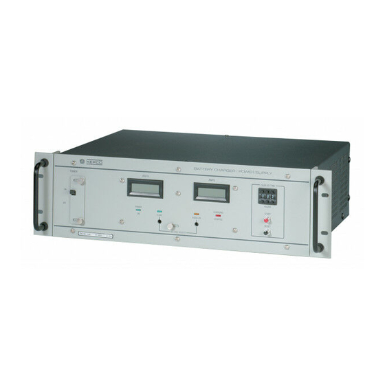
Page 4: Tbc Series Rack Mount Battery Charger Power Supply
FIGURE 1-1. TBC SERIES RACK MOUNT BATTERY CHARGER POWER SUPPLY TBC OPR 071019... -
Page 5: Section 1 - Introduction
Charger Power Supply manufactured by Kepco, Inc., Flushing, New York, U.S.A. GENERAL DESCRIPTION The Kepco TBC Series of Telecommunications Battery Chargers, hereafter referred to as TBC, consists of three major groups of Power Supplies. They are used for charging 12, 24, and 48 Volt batteries respectively, and are capable of delivering up to 120 Amps. -
Page 6: Float, Equalize, And Overvoltage Protection Specifications
(2) The Equalize voltage can not be set higher than the Overvoltage protection level. (3) For the following models V OVP is 120% ±7% of V SET - Latch-style tracking overvoltage protection: TBC 12-50M, TBC 12-100M, TBC 24-25M, TBC 24-50M, TBC 24-100M, TBC 48-12M, TBC 48-25M, and TBC 60-25M. Cycle power to reset. -
Page 7: General Specifications
TABLE 1-3. GENERAL SPECIFICATIONS SPECIFICATION RATING/DESCRIPTION CONDITION Input Characteristics Input Voltage Nominal: 100 - 120V a-c, 220 - 240V a-c Single Phase, Wide Range Range: 85 - 264V a-c Frequency Nominal: 50 - 60Hz Range: 47 - 63Hz Leakage 100 - 120V a-c Input <1.0mA a-c max. -
Page 8: Overvoltage Protections And Special Features
OVERVOLTAGE PROTECTIONS AND SPECIAL FEATURES The TBC incorporates switching power supplies with power factor correction (PFC). A Control Board in the TBC controls and monitors critical functions of the TBC Battery Charger. The front panel contains a main Circuit Breaker, voltage and current meters, status indicators (LED), and an Equalize Timer control. -
Page 9: Tbc Mechanical Outline Drawing
FIGURE 1-2. TBC MECHANICAL OUTLINE DRAWING -4/(-5 # 071019 1-5/(1-6 Blank) -
Page 11: Section 2 - Installation
SECTION 2 - INSTALLATION UNPACKING AND INSPECTION This instrument has been thoroughly inspected and tested prior to packing and is ready for operation. After unpacking, inspect for shipping damage before attempting to operate. Perform the preliminary inspection as outlined in the following paragraph. If any indication of damage is found, file an immediate claim with the responsible transport service. -
Page 12: Tbc Series (Except Tbc 24-120M And Tbc 48-60M) Front Panel Controls And Indicators
FIGURE 2-1. TBC SERIES (EXCEPT TBC 24-120M AND TBC 48-60M) FRONT PANEL CONTROLS AND INDICATORS FIGURE 2-2. TBC 24-120M AND TBC 48-60M FRONT PANEL CONTROLS AND INDICATORS b. Rear Panel: The TBC has two output power terminals for connecting to the battery and/ or load. -
Page 13: Tb1 Input/Output Terminal Assignments
TABLE 2-2. TB1 INPUT/OUTPUT TERMINAL ASSIGNMENTS TERMINAL NO. NAME DESCRIPTION OR FUNCTION Control With a jumper between these terminals and the battery connected, the TBC Con- trol Board will remain ON even if the AC Circuit Breaker is OFF. With the jumper ON/OFF removed the Control Board will go OFF if the AC Circuit Breaker is OFF. -
Page 14: Ac Source Power Requirements
FIGURE 2-3. TBC REAR PANEL AC SOURCE POWER REQUIREMENTS The TBC Battery Charger Power Supply is supplied for operation on a single phase line with a-c input voltage between 100V and 250V a-c nominal (universal a-c input). The circuit breaker remains effective at all input voltages. -
Page 15: Cooling
FIGURE 2-4. AC INPUT POWER TERMINAL BLOCK, TB3 COOLING The power transistors and rectifiers in the TBC Battery Charger Power Supply are maintained within their operating temperature range by means of special heat sink assemblies, cooled by internal fans. CAUTION: SIDE PANEL OPENINGS AND THE TOP OF THE CASE MUST BE KEPT CLEAR FROM OBSTRUCTIONS TO ENSURE PROPER AIR CIRCULATION. -
Page 16: Rack Panel Mounting
To release the circuit breaker locking plate loosen the two knurled head screws (6-32 x 1/2) and slide the locking plate to the right (see Figure 2-5A). For models TBC 24-120M and TBC 48-60M slide the locking plate down (see Figure 2-5B). FIGURE 2-5. -
Page 17: Rack Mounting
FIGURE 2-6. RACK MOUNTING 2-7/(2-8 Blank) TBC OPR 071019... -
Page 19: Section 3 - Operating Instructions
SECTION 3 - OPERATING INSTRUCTIONS GENERAL Interconnections between a stabilized Battery Charger Power Supply, and its load are as critical as the interface between other types of electronic equipment. If optimum performance is expected, certain rules for the interconnections must be observed by the user. These rules are described in detail in the following paragraphs. -
Page 20: Load Connection, Method 2 (Remote Error Sensing)
FIGURE 3-1. LOCAL ERROR SENSING CONNECTIONS LOAD CONNECTION, METHOD 2 (REMOTE ERROR SENSING) To avoid excessive output effects at remote loads, remote error sensing must be used. The links between the +S and + M terminals and between the -S and -M terminals must be removed. Use a twisted, shielded pair of wires from the Sensing Terminals directly to the load to compensate for load wire voltage drops. -
Page 21: Parallel Operation
FIGURE 3-2. REMOTE ERROR SENSING CONNECTIONS PARALLEL OPERATION Up to three identical TBC Battery Charger Power Supplies can be connected in parallel opera- tion, except for models TBC 48-60M and TBC 24-120M, which have two power supplies in par- allel that are built into the units. For the TBC 48-60M or TBC 24-120M only one additional TBC unit can be connected in parallel. -
Page 22: Suggested Wiring For Up To Three Tbc Units With Remote Sensing And Remote Control
FIGURE 3-3. SUGGESTED WIRING FOR UP TO THREE TBC UNITS WITH REMOTE SENSING AND REMOTE CONTROL TBC OPR 071019...
Need help?
Do you have a question about the TBC 12-50M and is the answer not in the manual?
Questions and answers