Table of Contents
Advertisement
Quick Links
Advertisement
Table of Contents

Related Manuals for BECKWITH ELECTRIC M-3425A


Summary of Contents for BECKWITH ELECTRIC M-3425A
- Page 1 Instruction Book Part 1 of 2 M-3425A Generator Protection...
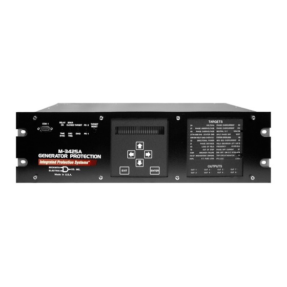
- Page 2 PROTECTION Generator Protection M-3425A ® Integrated Protection System for Generators of All Sizes Unit shown with optional M-3925A Target Module and M-3931 HMI (Human-Machine Interface) Module. • Exceeds IEEE C37.102 and Standard 242 requirements for generator protection • Protects generators of any prime mover, grounding and connection type •...
- Page 3 M-3425A Generator Protection Relay Optional Protective Functions Protective Functions • Sync Check with Phase Angle, ΔV and ΔF Base Package with dead line/dead bus options (25) • Overexcitation (V/Hz) (24) • Field Ground (64F) and Brush Lift Off (64B) • Phase Undervoltage (27) (Includes M-3921 Field Ground Coupler) •...
- Page 4 M-3425A Generator Protection Relay PROTECTIVE FUNCTIONS Device Setpoint Number Function Ranges Increment Accuracy † Phase Distance (three-zone mho characteristic) 0.1 to 100.0 Ω 0.1 Ω 0.1 Ω or 5% Circle Diameter #1,#2,#3 (0.5 to 500.0 Ω) ( 0.5 Ω or 5%) –100.0 to 100.0 Ω...
- Page 5 M-3425A Generator Protection Relay PROTECTIVE FUNCTIONS ( cont .) Device Setpoint † Number Function Ranges Increment Accuracy Third-Harmonic Undervoltage, Neutral Pickup #1, #2 0.10 to 14.00 V 0.01 V 0.1 V or Positive Sequence Voltage Block 5 to 180 V 0.5 V or...
- Page 6 ( 0.02 A or Time Delay 1 to 8160 Cycles 1 Cycle 1 Cycle or 50BF can be initiated from designated M-3425A output contacts or programmable control/status inputs. Definite Time Overcurrent Pickup Phase A #1, #2 0.20 A to 240.00 A 0.01 A 0.1 A or...
- Page 7 M-3425A Generator Protection Relay PROTECTIVE FUNCTIONS ( cont .) Device Setpoint Number Function Ranges Increment Accuracy † Instantaneous Neutral Overcurrent Pickup 0.1 to 240.0 A 0.1 A 0.1 A or (0.1 to 48.0 A) ( 0.02 A or Time Delay...
- Page 8 M-3425A Generator Protection Relay PROTECTIVE FUNCTIONS ( cont .) Device Setpoint Number Function Ranges Increment Accuracy † Phase Overvoltage Pickup #1, #2, #3 5 to 180 V 0.5 V or 0.5% 0.8 V or 0.75%* Time Delay #1, #2, #3...
- Page 9 M-3425A Generator Protection Relay PROTECTIVE FUNCTIONS ( cont .) Device Setpoint Number Function Ranges Increment Accuracy † Residual Directional Overcurrent Definite Time* Pickup 0.5 to 240.0 A 0.1 A 0.1 A or (0.1 to 48.0 A) ( 0.02 A or...
- Page 10 M-3425A Generator Protection Relay PROTECTIVE FUNCTIONS ( cont .) Device Setpoint Number Function Ranges Increment Accuracy † Frequency Accumulation Frequency Accumulation Frequency Accumulation Frequency Accumulation Frequency Accumulation Bands #1, #2, #3, #4, #5, #6 High Band #1 50.00 to 67.00 Hz 0.01 Hz...
- Page 11 M-3425A Generator Protection Relay PROTECTIVE FUNCTIONS ( cont .) Device Setpoint Number Function Ranges Increment Accuracy † IPSlogic IPSlogic uses element pickups, element trip commands, control/status input state changes, output contact close signals to develop 6 programmable logic schemes. Time Delay #1–#6...
- Page 12 M-3425A Generator Protection Relay OPTIONAL PROTECTIVE FUNCTIONS Device Setpoint † Number Function Ranges Increment Accuracy Sync Check Dead Check Dead Voltage Limit 0 to 60 V 0.5 V or ±0.5% Dead Time Delay 1 to 8160 Cycles 1 Cycle –1 to +3 Cycles or 1%...
- Page 13 M-3425A Generator Protection Relay Description The M-3425A Generator Protection Relay is suitable for all generator ratings and prime movers. Typical connection diagrams are illustrated in Figure 4, M-3425A One-Line Functional Diagram (configured for phase differential), and Figure 5, One-Line Functional Diagram (configured for split-phase differential).
- Page 14 M-3425A Generator Protection Relay Sequence of Events Log The Sequence of Events Log records relay element status, I/O status, measured values and calculated values time stamped with 1 ms resolution at user-defined events. The Sequence of Events Log includes 512 of the most recently recorded relay events.
- Page 15 When the optional Ethernet port is purchased it also provides MODBUS over TCP/IP and BECO2200 over TCP/IP protocols. IRIG-B The M-3425A Generator Protection Relay can accept either modulated or demodulated IRIG-B time clock synchronization signal. The IRIG-B time synchronization information is used to correct the hour, minutes, seconds, and milliseconds information.
- Page 16 M-3425A Generator Protection Relay Temperature Controller Monitoring Any Temperature Controller equipped with a contact output may be connected to the M-3425A and controlled by the relay's IPSlogic function. Figure 1 is an example of a typical Temperature Controller Monitoring application.
- Page 17 M-3425A Generator Protection Relay Electrical Environment Electrostatic Discharge Test EN 60255-22-2 Class 4 (8 kV)—point contact discharge EN 60255-22-2 Class 4 (15kV)–air discharge Fast Transient Disturbance Test EN 60255-22-4 Class A (4 kV, 2.5 kHz) Surge Withstand Capability ANSI/IEEE 2,500 V pk-pk oscillatory applied to each independent circuit to earth C37.90.1-...
- Page 18 Patent & Warranty The M-3425A Generator Protection Relay is covered by U.S. Patents 5,592,393 and 5,224,011. The M-3425A Generator Protection Relay is covered by a five year warranty from date of shipment. Specification subject to change without notice. External Connections M-3425A external connection points are illustrated in Figures 2 and 3.
- Page 19 M-3425A Generator Protection Relay –18–...
- Page 20 M-3425A Generator Protection Relay –19–...
- Page 21 When 67N function with I (Residual) operating current is enabled, 87GD is not available, and vice versa. When VT source is used as a turn-to-turn fault protection device (See M-3425A Instruction Book, Chapter 2, Application, for additional 59X applications.) The current input I can be connected either from neutral current or residual current.
- Page 22 The 50BFN, 50N, 51N, 59D, 67N (with I or V ) and 87GD functions are unavailable when the 64S function has been purchased. See the M-3425A Instruction Book for connection details. Figure 5 One-Line Functional Diagram (configured for split-phase diffential) –21–...
- Page 23 M-3425A Generator Protection Relay 17.48 [44.4] ACTUAL 5.21 [13.23] ACTUAL Rear View 10.20 [25.91] 19.00 [48.26] 19.00 [48.26] 0.33 18.34 [46.58] [0.84] 0.40 [1.02] x 0.27 [0.68] SLOT (4x) 2.35 [5.96] 1.35 [3.42] Standard 19" Horizontal Mount Chassis n NOTE: Dimensions in brackets are in centimeters.
- Page 24 M-3425A Generator Protection Relay 10.20 [25.9] 19.00 [48.26] .25 X .45 SLOT [.64 X 1.14] 4 PLACES OUTPUTS TARGET RELAY BRKR 4.00 COM 1 TARGET CLOSED TARGET PS 1 RESET [10.16] TIME OSC. PS 2 6.96 SYNC TRIG [17.68] M-3425A...
- Page 25 ■ NOTES: When mounted vertically, the target module will be located at the top and all front-panel text will be horizontally aligned. Consult Beckwith Electric Co. for details. Expanded I/O not avilable on vertical mount chassis model. Figure 8 Vertical Mounting Dimensions (Without Expanded I/O)
- Page 26 \U+2205.28 (4X) RECOMMENDED CUTOUT STANDARD 3 UNIT PANEL M-3425A 18.34 [46.17] 17.50 [.86] [44.45] 1.48 [3.76] 7.03 [17.86] 4.00 [10.16] \U+2205.28 (4X) RECOMMENDED CUTOUT 4 UNIT PANEL M-3425A (EXTENDED I/O) TOLERANCE: .XX±.015 Figure 9 M-3425A Panel Mount Cutout Dimensions –25–...
- Page 27 M-3425A Generator Protection Relay M-3921 Field Ground Coupler PROTECTION RELAY M-3425A PROCESSOR Excitation System Field Ground Brushes Detection Squarewave Gen. Generator Rotor COUPLING Signal NETWORK Measurement and Processing (M-3921) Shaft Ground Brush Ground/Machine Frame Figure 10 Field Ground Protection Block Diagram...
- Page 28 1989 5,000 V pk Fast Transient applied to each independent circuit to earth 5,000 V pk Fast Transient applied between each independent circuit ■ NOTE: See also M-3425A Surge Withstand Capability test standards, ANSI/IEEE C37.90.2-2002. Radiated Susceptibility ANSI/IEEE 25-1000 Mhz @ 20 V/m C37.90.2...
-
Page 29: Printed In U.s.a. (9
Figure 11 M-3921 Field Ground Coupler Mounting Dimensions BECKWITH ELECTRIC CO., INC. 6190 - 118th Avenue North • Largo, Florida 33773-3724 U.S.A. PHONE (727) 544-2326 • FAX (727) 546-0121 E-MAIL marketing@beckwithelectric.com WEB PAGE www.beckwithelectric.com © 2001 Beckwith Electric Co. Printed in U.S.A. (#01-67) (04.25.03) 800-3425A-SP-01MC5 1/06... - Page 30 WARNING DANGEROUS VOLTAGES, capable of causing death or serious injury, are present on the external terminals and inside the equip- ment. Use extreme caution and follow all safety rules when han- dling, testing or adjusting the equipment. However, these internal voltage levels are no greater than the voltages applied to the exter- nal terminals.
- Page 31 PRODUCT CAUTIONS Before attempting any test, calibration, or maintenance procedure, personnel must be completely familiar with the particular circuitry of this unit, and have an adequate understanding of field effect devices. If a component is found to be defective, always follow replacement procedures carefully to that assure safety features are maintained.
- Page 32 NOTE The following features, described in this Instruction Book, are only available for firmware version D-0150-V01.00.33 and later: 59N 20 Hz Injection Mode (Page 2-58) IEEE curves for 51N, 51V, and 67N functions (Appendix D) Sequence of Events Recorder (Page 4-18) Dropout/Reset Time Delay added to IPSlogic (Page 2-91) Response Time Delay for Communications (Page 4-3) 25 Function (does not produce a target) (Page 2-21)
- Page 33 This Page Left Intentionally Blank...
-
Page 34: Table Of Contents
M-3425A Generator Protection Instruction Book Chapters - Part 1 of 2 Page Chapter 1 Introduction Instruction Book Contents ..............1–1 M-3425A Generator Protection Relay ..........1–2 Accessories ..................1–4 Chapter 2 Application Configuration ..................2–1 Profiles ....................2–2 Functions .................... 2–2 Special Considerations ................ -
Page 35: Chapters - Part 1 Of
M-3425A Instruction Book Chapters - Part 1 of 2 (cont'd) Page Chapter 2 Application (cont'd) 67N Residual Directional Overcurrent ..........2–70 78 Out of Step .................. 2–73 81 Frequency ..................2–76 81A Frequency Accumulators ............2–78 81R Rate of Change of Frequency ............2–80 87 Phase Differential ................ - Page 36 Serial Ports (RS-232) ................. 4–1 Serial Port (RS-485) ................4–1 Optional Ethernet Port ................. 4–1 Direct Connection ................4–2 Setting up the M-3425A Generator Protection Relay for Communication ..............4–3 Serial Communication Settings............4–3 Ethernet Communication Settings ............4–3 DHCP Protocol ..................4–3 Ethernet Protocols ................
- Page 37 M-3425A Instruction Book Figures - Part 1 of 2 Page Chapter 1 M-3925A Target Module ..............1–3 M-3931 Human-Machine Interface (HMI) Module......1–4 Chapter 2 Setup System Dialog Box ..............2–5 Selection Screen for Expanded Input ..........2–6 Pulse Relay Expanded Output Screen ..........2–6 Latch Relay Expanded Output Screen ..........
- Page 38 Table of Contents Figures - Part 1 of 2 Page Chapter 2 (cont'd) 2-26 Tripping on Over Reactive Power with Element #3 (Over Power, Positive Pickup and Directional Power Sensing Set to Reactive) ................2–33 2-27 Directional Power, 3-Phase (32) Setpoint Ranges ......2–34 2-28 Loss of Field (40) Protective Approach 1 ........
- Page 39 Selection Screen for Initiating Function Pickup ........2–90 2-79 Dropout Delay Timer Logic Diagram ........... 2–91 2-80 Reset Delay Timer Logic Diagram ............2–91 Chapter 3 M-3425A Front Panel ................. 3–3 Screen Message Menu Flow ............. 3–3 Main Menu Flow ................. 3–4...
- Page 40 Table of Contents Figures - Part 1 of 2 (cont'd) Page Chapter 4 Multiple System Addressing Using Communications Line Splitter ............4–2 ® IPScom Menu Selections ..............4–6 IPScom Program Icon ................ 4–8 New Device Profile Dialog Box ............4–9 Communication Dialog Box ..............
- Page 41 4-47 Setup Dialog Box ................4–33 Tables - Part 1 of 2 Page Chapter 1 M-3425A Device Functions ..............1–2 Chapter 2 Input Activated Profile ............... 2–3 Impedance Calculation ..............2–17 Voltage Control Time Settings ............2–36 Delta/Wye Transformer Voltage-Current Pairs ........ 2–54 Typical Frequency Settings .............
- Page 42 Table of Contents Chapters - Part 2 of 2 Page Chapter 5 Installation General Information ................5–1 Mechanical/Physical Dimensions ............5–1 External Connections ................. 5–9 Commissioning Checkout ..............5–15 Circuit Board Switches and Jumpers ..........5–20 Chapter 6 Testing Equipment/Test Setup ................ 6–2 Functional Test Procedures ...............
- Page 43 M-3425A Instruction Book Chapters - Part 2 of 2 (cont'd) Page Chapter 6 Testing (cont'd) 87 Phase Differential ................6–59 87GD Ground Differential ..............6–61 BM Breaker Monitoring ............... 6–63 Trip Circuit Monitoring .................6–65 IPSlogic™ ..................6–66 Diagnostic Test Procedures ............... 6–67 Overview.....................
- Page 44 Table of Contents Figures - Part 2 of 2 Page Chapter 5 M-3425A Mounting Dimensions – Horizontal Chassis ..... 5–2 M-3425A Mounting Dimensions – Horizontal Chassis (Expanded I/O) ..............5–3 M-3425A Panel Mount Cutout Dimensions .......... 5–4 M-3425A Mounting Dimensions – Vertical Chassis ......5–5 (H2) Mounting Dimensions ..............
- Page 45 M-3425A Instruction Book Figures (cont'd) Page Chapter 6 (cont'd) 6-14 Voltage Input Configuration ..............6–79 6-15 Voltage Input Configuration ..............6–79 6-16 Voltage Input Configuration ..............6–80 Appendix A Human-Machine Interface (HMI) Module ...........A–6 Communication Data & Unit Setup Record Form ......A–7 Functional Configuration Record Form ..........
- Page 46 Self-Test Error Codes ................ C–1 ® IPScom Error Messages ..............C–2 Appendix D D-1A M-3425A Inverse Time Overcurrent Relay Characteristic Curves ... D–6 Appendix E Declaration of Conformity ..............E–2 ©1998 Beckwith Electric Co. Printed in U.S.A. (9.21.01) 800-3425A-IB-01MC6 01/06...
- Page 47 M-3425A Instruction Book This Page Left Intentionally Blank...
-
Page 48: Chapter 1 Introduction
Chapter Two is designed for the person or group and all external connections in this chapter. For responsible for the application of the M-3425A reference, the Three-Line Connection Diagram is Generator Protection Relay. It includes functional repeated from Chapter 2, Application. -
Page 49: M-3425A Generator Protection Relay
IRIG-B time- M-3425A Generator sync capability for accurate time-tagging of events. Protection Relay The M-3425A Generator Protection Relay is a microprocessor-based unit that uses digital signal processing technology to provide up to thirty-four protective relaying functions for generator protection. - Page 50 Introduction – 1 Communication Ports There are three physical communication ports i t c provided on the M-3425A. If the optional RJ45 t s i Ethernet port is purchased, then the relay includes r e t t s i ) c i...
-
Page 51: Accessories
® M-3801D IPSplot Oscillograph Analysis PLUS Software Package The IPSplot Oscillograph Analysis Software PLUS ® runs conjunction with IPScom Communications Software PC-compatible computer, enabling the plotting, printing, and analysis of waveform data downloaded from the M-3425A Generator Protection Relay. 1–4... -
Page 52: Chapter 2 Application
Setpoints and Time Settings ........... 2–13 Chapter Two is designed for the person or group Configuration responsible for the application of the M-3425A Generator Protection Relay. It includes functional and connection diagrams for a typical application of Configuration of the relay consists of enabling the the relay;... -
Page 53: Profiles
M-3425A Instruction Book Control/status input IN1 is preassigned to be the The relay allows the user to designate up to six 52b breaker status contact. If a multiple breaker logic functions which perform similarly to internal scheme is used, the control/status input IN1 must relay functions, using IPSlogic . -
Page 54: Relay System Setup
30° phase dis delta_ab delta_ac shift for 51V and 21 functions. This screen allows the user to select the phase rotation of the M-3425A PHASE ROTATION to match the generator. a-c-b a-b-c 2–3... - Page 55 M-3425A Instruction Book This screen allows the selection of RMS or DFT for the 59 and 27 59/27 MAGNITUDE SELECT functions. The magnitude can be selected as the RMS of the total rms dft waveform (including harmonics) or the RMS of the 60/50 Hz fundamental component of the waveform using the Discrete Fourier Transform (DFT).
-
Page 56: Setup System Dialog Box
Application – 2 SETUP SETUP SYSTEM Nominal Frequency: 60 Hz C.T. Secondary Rating: 5A Nominal Voltage: 140.0 V 50.0 V Delta-Y Transform Nominal Current: 5.00 0.50 A 6.00 A Disable Delta-AB Delta-AC Input Active State: Input Active State Expanded O p e n O p e n O p e n O p e n... -
Page 57: Selection Screen For Expanded Input
M-3425A Instruction Book Figure 2-2 Selection Screen for Expanded Input Pulse Relay Expanded Outputs OUTPUT9 OUTPUT17 OUTPUT10 OUTPUT18 OUTPUT11 OUTPUT19 OUTPUT12 OUTPUT20 OUTPUT13 OUTPUT21 Cancel OUTPUT14 OUTPUT22 OUTPUT15 OUTPUT23 OUTPUT16 Figure 2-3 Pulse Relay Expanded Output Screen Figure 2-4 Latch Relay Expanded Output Screen... -
Page 58: System Diagrams
The 50BFN, 50N, 51N, 59D, 67N (with I or V ) and 87GD functions are unavailable when the 64S function has been purchased. See the M-3425A Instruction Book for connection details. Figure 2-5 One-Line Functional Diagram 2–7... - Page 59 The 50BFN, 50N, 51N, 59D, 67N (with I or V ) and 87GD functions are unavailable when the 64S function has been purchased. See the M-3425A Instruction Book for connection details. Figure 2-6 Alternative One-Line Functional Diagram (configured for split-phase differential) 2–8...
-
Page 60: Three-Line Connection Diagram
Application of external voltage on these inputs may result in damage to the units. NOTE : M-3425A current terminal polarity marks ( . ) indicate "entering" current direction when M-3425A primary current is "from" the generator to the Three VT Wye-Wye system. -
Page 61: Function 25 Sync Check Three-Line Connection Diagram
M-3425A Instruction Book M-3425A Used when Generator Side VTs are connected Line-Ground. Used for Sync Check (25) M-3425A Used when Generator Side VTs are connected Line-Line M-3425A M-3425A Three VT Wye-Wye Connection M-3425A Two VT Open-Delta Connection Generator ■ NOTE: When V is connected for Sync Check function (25), turn-to-turn fault protection (59X) is not available. -
Page 62: Function 59X Turn-To-Turn Fault Protection Three-Line Connection Diagram
Application – 2 M-3425A M-3425A used for turn-to-turn fault protection (59X) Generator Line to Neutral Voltage Rated Cable M-3425A M-3425A Low Impedance Grounding High Impedance Grounding ■ NOTE: When V is connected for turn-to-turn fault protection, 59X and 25 functions are not available. -
Page 63: Function 67N, 59D, 59X (Bus Ground) Three-Line Connection Diagram
M-3425A Instruction Book Bus Section M-3425A input can be connected Residual CT either at Neutral or as Residual. M-3425A Connection M-3425A Bus Ground M-3425A 67N, 59D Connection can be used for both 67N and Generator 59D if connected in this manner. -
Page 64: Setpoints And Time Settings
Application – 2 Setpoints and Time Settings The individual protective functions, along with their magnitude and timing settings are described in the following pages. Settings for disabled functions do not apply. Some menu and setting screens do not appear for functions that are disabled or not purchased. Menu screens are as they would appear on units equipped with the M-3931 HMI Module. -
Page 65: Phase Distance
M-3425A Instruction Book 21 Phase Distance The Phase Distance function (21) is designed for When the generator is connected to the system system phase fault backup protection and is through a delta/wye transformer, proper voltages implemented as a three-zone mho characteristic. -
Page 66: Phase Distance (21) Coverage
Protected Range Zone 1 –R –X M-3425A Figure 2-12 Phase Distance (21) Coverage ■ NOTE: The reach settings of the distance elements (21) should not include generator impedance since the distance measurement starts at the VT location. However, since the neutral side CTs are used for this function, backup protection for generator Phase-to-Phase faults is also provided 2–15... -
Page 67: Phase Distance (21) Function Applied For System Backup
M-3425A Instruction Book ZONE 3 Transmission Line ZONE 2 Circle Diameters ZONE 1 Unit Transformer Block Block –R –jX Zone 1 Load Encroachment Blinder R Reach Zone 2 Load Encroachment Blinder R Reach δ1 Zone 1 Load Encroachment Blinder Angle δ2... -
Page 68: Phase Distance
Application – 2 (21) PHASE DISTANCE 0.1 Ohm 100.0 Ohm(s) Circle Diameter: -100.0 Ohm(s) 100.0 Ohm(s) Offset: 0° 90° Impedance Angle: 1° Load Encr. Angle: 90° Enable 0.1 Ohm 100.0 Ohm(s) Load Encr. R Reach: Disable 8160 Cycles 1 Cycle Delay: Enable 0.1 A... -
Page 69: Overexcitation Volts/Hz
M-3425A Instruction Book 24 Overexcitation Volts/Hz The Volts-Per-Hertz function (24) provides Setting this relay function involves determining the overexcitation protection for the generator and unit- desired protection levels and operating times. The connected transformers. This function incorporates first step is to plot the combined generator and... -
Page 70: Example Of Capability And Protection Curves (24)
#1 The operating time of the inverse time M-3425A Firmware Version D-0150V 01.00.34 element at the definite time element #1 The inverse time element has a definite minimum pickup should be greater than the definite time of 30 cycles. -
Page 71: Volts-Per-Hertz (24) Setpoint Ranges
M-3425A Instruction Book (24) - VOLTS/HZ 100% 200% Def. Time #1 Pickup: Delay: 30 Cycles 8160 Cycles OUTPUTS Blocking Inputs Expanded I/O’s 100% 200% Def. Time #2 Pickup: Delay: 30 Cycles 8160 Cycles OUTPUTS Blocking Inputs Expanded I/O’s Inv. Time... -
Page 72: Sync Check
Application – 2 25 Sync Check ■ NOTE: The 25 function cannot be enabled under Dead Line/Dead Bus Check any one of the following conditions: The Dead Volt Limit defines the Hot/Dead voltage • 67N (Residual Directional Overcurrent) level used in Deadline/Dead Bus closing schemes. is enabled and the polarizing quantity When the measured V voltage is equal to or below... - Page 73 M-3425A Instruction Book If this function is enabled, the following settings are applicable: Phase angle setting. 25S PHASE LIMIT ________ Degrees Upper voltage limit for voltage acceptance. 25S UPPER VOLT LIMIT ________ Volts Lower voltage limit for voltage acceptance. 25S LOWER VOLT LIMIT ________ Volts Sync check time delay.
-
Page 74: Sync Check Logic Diagrams
Application – 2 Delta V and Delta F Check Logic With Delta V AND Delta F Enabled Only one Delta V and |V 1 - V X | < Delta V Limit Delta F Check Scheme may be active at a time. Delta V Is Enabled Phase Angle Check Logic |F 1 - F X | <... -
Page 75: Sync Check
M-3425A Instruction Book (25) - SYNC CHECK Phase Angle Window: 60 V 140 V Upper Voltage Limit: 40 V 120 V Lower Voltage Limit: 1 Cycle 8160 Cycles Sync Check Delay: Delta Voltage: 1.0 V 50.0 V Enable Disable Delta Frequency: 0.001 Hz... -
Page 76: Phase Undervoltage
Application – 2 27 Phase Undervoltage Magnitude measurement depends on the 59/27 The Phase Undervoltage function (27) may be used to detect any condition causing long- or short-term Magnitude Select setting. (See Section 2.1, Configuration, Relay System Setup.) When the RMS undervoltage. -
Page 77: 27Tn Third Harmonic Undervoltage, Neutral
To properly handle pump storage operations, the will display those values directly, no additional M-3425A forward power blocking algorithm is enable equipment is required. The undervoltage inhibit from “zero per unit” to the forward power setpoint. -
Page 78: Third-Harmonic Undervoltage (27Tn) Protection Characteristics
Application – 2 27TN #1 LAG VAR BLK 27TN #1 BAND FWD PWR BLK disable ENABLE disable enable 27TN #1 LAG VAR BLK 27TN#1 LO B FWD PWR BLK ________ PU ________ PU 27TN #1 LEAD PF BLK 27TN#1 HI B FWD PWR BLK ________ PU disable enable... -
Page 79: Tn Blocking Regions
M-3425A Instruction Book Low Band Forward Lag var Block Power Block Forward Block Block Reverse High Band Power Power Forward Block Block Power Block Lead var Block Figure 2-21 27TN Blocking Regions 2–28... -
Page 80: Third Harmonic Undervoltage, Neutral Circuit (27Tn Setpoint Ranges
Application – 2 (27TN) - THIRD HARMONIC UNDERVOLTAGE, NEUTRAL Pickup: 0.1 V 14.00 V Pos. Seq. Voltage Block: 180 V Enable Disable 0.01 PU Forward Power Block: 1.00 PU Enable Disable -1.00 PU Reverse Power Block: -0.01 PU Enable Disable Lead var Block: -0.01 PU -1.00 PU... -
Page 81: Directional Power
M-3425A Instruction Book 32 Directional Power The Directional Power function (32) can provide valves are closed. In this case the Over/Under protection against both generator motoring and power setting is set to Under and a positive pickup overload. It provides three power setpoints, each setting is chosen. - Page 82 Application – 2 32 #2 TARGET LED disable enable 32#2 UNDER/OVER POWER over under 32 #3 PICKUP ________ PU 32 #3 DELAY ________ Cycles 32 #3 TARGET LED disable enable 32#3 UNDER/OVER POWER over under Directional Power Sensing for Element #3 can be se- 32 #3 DIR POWER SENSING lected as Real or Reactive.
-
Page 83: Tripping On Overpower (Over Power With Positive Pickup)
M-3425A Instruction Book Figure 2-24 Tripping on Low Forward Power (Under Power with Positive Pickup) Figure 2-25 Tripping on Overpower (Over Power with Positive Pickup) 2–32... -
Page 84: Tripping On Over Reactive Power With
Application – 2 Figure 2-26 Tripping on Over Reactive Power with Element #3 (Over Power, Positive Pickup and Directional Power Sensing Set to Reactive) 2–33... -
Page 85: Directional Power, 3-Phase (32) Setpoint Ranges
M-3425A Instruction Book (32) - DIRECTIONAL POWER -3.000 PU 3.000 PU Pickup: 1 Cycle 8160 Cycles Delay: Overpower Underpower Target LED Enable OUTPUTS Blocking Inputs Expanded I/Os -3.000 PU 3.000 PU Pickup: Delay: 1 Cycle 8160 Cycles Overpower Underpower Target LED Enable... -
Page 86: Loss Of Field
Two approaches are widely used in the industry, both of which are The loss-of-field function is implemented with two supported by the M-3425A relay. Both approaches offset mho elements, an undervoltage element, require knowledge of the reactances and other and a directional element. -
Page 87: Voltage Control Time Settings
M-3425A Instruction Book The second approach is shown in Figure 2-29, 40 #2 DIAMETER Loss of Field (40) – Protective Approach II. In ________ Ohms this approach, one of the mho elements is set with an offset of –X ÷ 2, a diameter of 1.1 X ÷... -
Page 88: Loss Of Field (40) Protective Approach 1
Application – 2 Heavy Load Light Load –R Underexcited –X Figure 2-28 Loss of Field (40)—Protective Approach 1 Directional Element Block Direction Heavy Load Light Load Trip Direction –R Directional Element Angle Setting Underexcited –X Figure 2-29 Loss of Field (40)—Protective Approach 2 2–37... -
Page 89: Loss Of Field (40) Setpoint Ranges
M-3425A Instruction Book Figure 2-30 Loss-of-Field (40) Setpoint Ranges ■ NOTE: Out of Step Block Enable is not available for this release, and will appear greyed-out in display. 2–38... -
Page 90: Negative Sequence Overcurrent
Application – 2 46 Negative Sequence Overcurrent value, the trip timer takes four minutes to reset The Negative Sequence Overcurrent function (46) from its 100% trip level. Figure 2-31, Negative provides protection against possible rotor Sequence Overcurrent Inverse Time Curves, overheating and damage due to unbalanced faults illustrates the inverse time characteristic of the or other system conditions which can cause... -
Page 91: Negative Sequence Overcurrent Inverse Time Curves
M-3425A Instruction Book ■ ■ ■ ■ ■ NOTE: When the phase current exceeds 3X I nominal, the operating times will be greater than those shown. * 0.24 seconds for 50 Hz units. Figure 2-31 Negative Sequence Overcurrent Inverse Time Curves Figure 2-32 Negative Sequence Overcurrent (46) Setpoint Ranges 2–40... -
Page 92: Stator Overload Protection
Application – 2 49 Stator Overload Protection The Stator Thermal Overload function (49) provides loaded with 80% of its rating power prior to overload, protection against possible damage during overload then the current goes up to 2.0 times the maximum conditions. -
Page 93: Function Overload Curves
M-3425A Instruction Book 49 - Overload Curves 0.01 P=0.99 0.001 where: P= Figure 2-34 49 Function Overload Curves 2–42... -
Page 94: Stator Thermal Protection (49) Setpoint Ranges
Application – 2 Figure 2-35 Stator Thermal Protection (49) Setpoint Ranges 2–43... -
Page 95: Instantaneous Overcurrent (50) Setpoint Ranges
M-3425A Instruction Book 50/50N Instantaneous Overcurrent, Phase and Neutral Circuits The Instantaneous Phase (50) and Instantaneous automatically selects fundamental RMS or total Neutral (50N) overcurrent functions provide fast RMS calculation based on the input frequency. tripping for high fault currents. The settings of both... -
Page 96: Instantaneous Neutral Overcurrent (50N) Setpoint Ranges
Application – 2 Figure 2-37 Instantaneous Neutral Overcurrent (50N) Setpoint Ranges 2–45... -
Page 97: 50Bf Generator Breaker Failure/Hv Breaker Flashover
CT location and the generator 50BF-Ph Generator Breaker Failure: When the breaker, a possible area of mis-operation exists. M-3425A Generator Protection Relay detects an Usually the risk of faults in this limited area is small internal fault or an abnormal operating condition, it enough to be ignored but should be considered. -
Page 98: Breaker Failure Logic Diagram
Application – 2 If generator breaker failure function is used in this application, ENABLE 50BF PHASE ELEMENT here. disable enable 50BF PICKUP PHASE Set phase pickup amps. ________ Amps If the breaker flashover protection is to be used with the generator 50BF NEUTRAL ELEMENT breaker failure function of the relay, set ENABLE (enable phase disable... -
Page 99: Breaker Failure (50Bf) Setpoint Ranges
M-3425A Instruction Book Figure 2-39 Breaker Failure (50BF) Setpoint Ranges 2–48... -
Page 100: 50Dt Definite Time Overcurrent (For Split-Phase Differential)
Application – 2 50DT Definite Time Overcurrent (for split-phase differential) ■ NOTE: When 50DT function is used for split- The Definite Time Overcurrent (50DT) function can be applied in two different configurations based on phase differential, 50BF, 87 and 87GD functions must be disabled. -
Page 101: 50/27 Inadvertant Energizing
M-3425A Instruction Book 50/27 Inadvertent Energizing The Inadvertent Energizing function (50/27) of the in a matter of seconds. Voltage supervised relay is an overcurrent function supervised by overcurrent logic is designed to provide this generator terminal bus voltage. Inadvertent or protection. -
Page 102: Inadvertent Energizing Function Logic Diagram
Application – 2 Overcurrent I>PU Programmed Output Contacts Pickup Delay Undervoltage* V<PU Dropout Delay * On All Three Phases Simultaneously Figure 2-41 Inadvertent Energizing Function Logic Diagram F50/27 (50/27) - INADVERTENT ENERGIZING (50) - OVERCURRENT 50/27 Pickup: 0.50 A 15.00 A (27) - UNDERVOLTAGE Pickup: 130 V... -
Page 103: Inverse Time Neutral Overcurrent
M-3425A Instruction Book 51N Inverse Time Neutral Overcurrent one cycle time delay should be added to these The Inverse Time Neutral Overcurrent function (51N) curves in order to obtain the relay operating time. provides protection against ground faults. Since no... -
Page 104: Inverse Time Phase Overcurrent With Voltage Control/Restraint
Application – 2 51V Inverse Time Phase Overcurrent with 51V is a true three-phase function, in that the relay Voltage Control/Restraint incorporates separate integrating timers on each Time-overcurrent relays, one per phase, are used phase. to trip circuits selectively and to time-coordinate The inverse time overcurrent function can be voltage with other up- or downstream relays. -
Page 105: Voltage Restraint (51Vr) Characteristic
M-3425A Instruction Book Tap Setting as % of Tap Setting at Rated Voltage Input Voltage (% of rated voltage) Figure 2-44 Voltage Restraint (51VR) Characteristic Generator Connected Through Generator Directly Connected Delta AB/Wye or Delta AC/Wye Transformer Voltage Control or Restraint... -
Page 106: Phase Overvoltage
Application – 2 59 Phase Overvoltage Magnitude measurement depends on the 59/27 The Phase Overvoltage function (59) may be used Magnitude Select setting (See Section 2.1, to provide overvoltage protection for the generator. Configuration, Relay System Setup). When the The relay provides overvoltage protection functions RMS option is selected, the magnitude calculation with three voltage levels and three definite-time is accurate over a wide frequency range (10 to 80... -
Page 107: Third Harmonic Voltage Differential
M-3425A Instruction Book 59D Third Harmonic Voltage Differential (Ratio) operation of the differential relay (see Figure 2-20). This scheme, when used in conjunction with 59N The generator terminal voltage (Line Side Voltage) function may provide 100% Stator Ground fault can be selected as 3V (Calculated by the relay protection. -
Page 108: Third Harmonic Voltage Differential (59D) Setpoint Ranges
Application – 2 M-3425A The ratio V > Pickup Where: V is the Third Harmonic Triple Zero Sequence voltage measured at the generator terminals. is the Third Harmonic voltage measure at the neutral. Figure 2-47 Third Harmonic Voltage Differential (Ratio) Scheme for Generator Ground Fault... -
Page 109: Overvoltage, Neutral Circuit Or Zero Sequence
(high side of the GSU).) For applications where the M-3425A relay (where the 64S function is purchased or not) is used with 100% Stator Ground protection with 20 Hz injection schemes, the 59N 20 Hz injection mode must be enabled in order to calculate the voltage magnitude accurately for the 59N function, due to the 20 Hz injection voltage. -
Page 110: Multipurpose Overvoltage (Turn-To-Turn Stator Fault Or Bus Ground Protection)
Application – 2 59X Multipurpose Overvoltage (Turn-to-Turn Stator Fault Protection or Bus Ground Protection) faults. The relay will, however, operate for turn-to- For generators where the stator-winding configuration turn faults, which increase the 3V voltage above does not allow the application of split-phase low normal levels. - Page 111 M-3425A Instruction Book Figure 2-51 (59X) Multi-purpose Overvoltage Setpoint Ranges 2–60...
-
Page 112: 60Fl Vt Fuse Loss
Application – 2 60FL VT Fuse Loss Some functions may operate inadvertently when a The 60FL function does not have to be enabled in VT fuse is blown or an event causes a loss of one, order to use the FL as a blocking input in the relay two, or all three potentials to the relay. - Page 113 M-3425A Instruction Book 2–62...
-
Page 114: Fuse Loss (60Fl) Setpoint Ranges
Application – 2 Figure 2-53 Fuse Loss (60FL) Setpoint Ranges 2–63... -
Page 115: F Field Ground Protection
M-3425A Instruction Book 64B/F Field Ground Protection cabling between the coupler and relay exceeds 100 feet, provisions should be made for in circuit 64F Field Ground Detection calibration to nullify the effects of cabling A typical connection diagram for Field Ground capacitance. - Page 116 Application – 2 8 WARNING: Machine should be off-line and The following Table gives typical frequency settings based on the rotor capacitance. The rotor field excitation should be off during the capacitance can be measured with a capacitance capacitance measurement. meter by connecting the meter across the field ■...
-
Page 117: Brush Lift-Off Detection
M-3425A Instruction Book 64B Brush Lift-Off Detection ■ NOTE: Field breaker should be closed for the Brush Lift-Off Detection (64B) provides detection of open brushes of the rotor shaft. This function works capacitance measurements. in conjunction with the 64F Field Ground Detection... -
Page 118: 100% Stator Ground Protection By Low Frequency Signal Injection
M-3425A relay through a suitable voltage increase. The 64S function will issue a trip signal divider, that limits the M-3425A to O O O O O 200 V ac (the after a set time delay when the measured 20 Hz... -
Page 119: S Function Component Connection Diagram
M-3425A Instruction Book 20 Hz Supply Generator Voltage 20 Hz 430- Band Pass A(L1) 00426 Filter B(L2) C(L3) 430-00427 External Block Device 400A Neutral Operative Wiring Grounding Shielded Transformer High 400/5 A Voltage 20 Hz CT 430-00428 M-3425A Max. 200 V... -
Page 120: Stator Ground Protection (64S) Setpoint Ranges
Application – 2 F64S (64S) - 100% STATOR GROUND Pickup: 2 mA 40 mA Delay: 1 Cycle 8160 Cycles Undervoltage Inhibit: Enable Disable 30 V OUTPUTS Blocking Inputs Expanded I/O’s @ : WARNING, You have not selected an output! Save Cancel Figure 2-58 100% Stator Ground Protection (64S) Setpoint Ranges 2–69... -
Page 121: Residual Directional Overcurrent
M-3425A Instruction Book 67N Residual Directional Overcurrent The Residual Directional Overcurrent function (67N) provides both definite time and inverse time provides protection from ground faults. The 67N elements. The inverse time element provides several function can provide generator ground fault curves. - Page 122 Application – 2 67NDT PICKUP Pickup value for the 67N element. ________ Amps 67NDT DIR ELEMENT Directional discrimination enable. When disabled, this function disable ENABLE will work like a 50N. 67NDT DELAY Time Delay setting. ________ Cycles 67NIT PICKUP Inverse Time Pickup ________ Amps 67NIT DIR ELEMENT Directional discrimination enabled.
-
Page 123: Residual Directional Overcurrent (67N) Setpoint Ranges
M-3425A Instruction Book F67N (67N) - RESIDUAL DIRECTIONAL OVERCURRENT Pickup: 0.5 A 240.0 A Def. Time Delay: 1 Cycle 8160 Cycles Enable Disable Directional Element: OUTPUTS Blocking Inputs Expanded I/O’s Pickup: 0.25 A 12.00 A Inv. Time Time Dial: 11.0... -
Page 124: Out Of Step
Application – 2 78 Out-of-Step The Out-of-Step function (78) is used to protect the Consider, for example, Figure 2-62. If the Out-of- generator from out-of-step or pole slip conditions. step swing progresses to impedance Z ), the This function uses one set of blinders, along with a MHO element and the blinder A element will both supervisory MHO element. -
Page 125: Out-Of-Step Relay Characteristics
M-3425A Instruction Book Figure 2-61 Out-of-Step Relay Characteristics SYSTEM 1.5 X TRANS δ SWING LOCUS ELEMENT BLINDER ELEMENTS Figure 2-62 Out-of-Step Protection Settings 2–74... -
Page 126: Out-Of-Step (78) Setpoint Ranges
Application – 2 Figure 2-63 Out-of-Step (78) Setpoint Ranges 2–75... -
Page 127: Frequency
M-3425A Instruction Book 81 Frequency The Frequency function (81) provides either Sample settings of the 81 function are shown in overfrequency or underfrequency protection of the Figure 2-64. The frequency functions are generator. It has four independent pickup and time automatically disabled when the input voltage delay settings. -
Page 128: Example Of Frequency (81) Trip Characteristics
Application – 2 Over Frequency Magnitude #1 Trip 61.0 60.8 60.6 60.4 Over Frequency Magnitude #2 60.2 Over Frequency Over Frequency Time Delay #1 Time Delay #2 Time (cycles) 60.0 Under Frequency Under Frequency Time Delay #4 Time Delay #3 59.8 Under Frequency Magnitude #3... -
Page 129: Frequency Accumulators
M-3425A Instruction Book 81A Frequency Accumulator for the next band, i.e., Low Band #2 is the upper limit for Band #3, and so forth. Frequency bands Frequency Accumulation feature (81A) provides an must be used in sequential order, 1 to 6. Band #1 indication of the amount of off frequency operation must be enabled to use Bands #2–#6. -
Page 130: Frequency Accumulator (81A) Example Bands
Application – 2 Example- Band 81-1 HB #1 Band 81-1 LB #2 Band 81-2 LB #3 Band 81-3 LB #4 Band 81-4 LB #5 Band Time (mins) Figure 2-66 Frequency Accumulator (81A) Example Bands F81A (81A) FREQUENCY ACCUMULATOR High Pickup: 50.00 Hz 67.00 Hz Low Pickup:... -
Page 131: Rate Of Change Of Frequency
M-3425A Instruction Book 81R Rate of Change of Frequency The function also has an automatic disable feature The Rate of Change of Frequency function (81R) which disables 81R function during unbalanced can be used for load shedding or tripping faults and other system disturbances. This feature applications. -
Page 132: Phase Differential
Application – 2 87 Phase Differential The Phase Differential function (87) is a percentage For very high currents in large generators, the differential with an adjustable slope of 1–100%. proximity of CTs and leads in different phases can Although this protection is used to protect the cause unbalanced currents to flow in the machine from all internal winding faults, single- secondaries. -
Page 133: Differential Relay (87) Operating Characteristics
M-3425A Instruction Book SLOPE TRIP (4xset) ((I A x CTC)-I a ), ((I B x CTC)-I b ), ((I C x CTC)-I c ) BLOCK SLOPE (set) MIN PU =2xI Restraint Current ((I A x CTC)+I a )/2, ((I B x CTC)+I b )/2, ((I C x CTC)+I c )/2... -
Page 134: 87Gd Ground (Zero Sequence) Differential
Application – 2 87GD Ground (Zero Sequence) Differential The advantage of directional supervision is the security against ratio errors and CT saturation during The Zero Sequence Differential function (87GD) faults external to the protected generator. provides ground fault protection for low impedance grounded generator applications. -
Page 135: Breaker Monitoring
M-3425A Instruction Book Breaker Monitoring The Breaker Monitoring feature calculates an estimate the relay can operate a programmable output contact. of the per-phase wear on the breaker contacts by The accumulated value for each phase can be measuring and integrating the current (IT) or current displayed as an actual value. -
Page 136: Trip Circuit Monitoring
When the Output Contact is closed, no current selections. flows in the Trip Circuit Monitoring Input. If the M-3425A has issued a trip command to close the This function should be programmed to block when Output Contact and Trip Circuit Monitoring Input... -
Page 137: Trip Circuit Monitor (Tc) Setpoint Ranges
M-3425A Instruction Book Figure 2-74 Trip Circuit Monitor (TC) Setpoint Ranges 2–86... -
Page 138: Ipslogic
Application – 2 IPSlogic™ The relay provides six logic functions and associated Programming the IPSlogic can only be implemented IPSlogic. The logic functions can be used to allow ® through IPScom Communications Software. The external devices to trip through the relay, providing IPSlogic cannot be programmed using the Human- additional target information for the external device. - Page 139 M-3425A Instruction Book 2–88...
-
Page 140: Ipslogic
Application – 2 The IPSlogic Function can be programmed to Settings and Logic Applicable when perform any or all of the following tasks: IPSlogic™ Function(s) programmed using ® IPScom • Change the Active Setting Profile There are four initiating input sources: Initiating •... -
Page 141: Selection Screen For Initiating Function Timeout
M-3425A Instruction Book Initiating Function Timeout Figure 2-77 Selection Screen for Initiating Function Timeout Initiating Function Pickup Figure 2-78 Selection Screen for Initiating Function Pickup 2–90... -
Page 142: Dropout Delay Timer Logic Diagram
Application – 2 DO/RST (Dropout/Reset) Timer Feature The DO/RST timer can be set as either Dropout or Reset mode. The operation of the Dropout Delay Timer and the Reset Delay Timer are described below. Dropout Delay Timer The Dropout Delay Timer logic is presented in Figure 2-79. The Dropout Delay Timer feature allows the user to affect an output time delay that starts when the IPSlogic PU Status drops out (A) and can hold the Output (D) status true beyound the Output Seal In Delay value (C). - Page 143 M-3425A Instruction Book This Page Left Intentionally Blank 2–92...
-
Page 144: Chapter 3 Operation
Operation – 3 Operation Front Panel Controls ..............3–1 Initial Setup Procedure/Settings ..........3–5 Setup Unit Data ................3–5 Setup System Data ..............3–6 Status/Metering ................3–9 Target History ................3–10 This chapter contains information that describes Arrow Pushbuttons the operation of the M-3931 Human Machine Interface The left and right arrow pushbuttons are used to Module (HMI) and the M-3925A Target module. -
Page 145: Power Supply #1 (#2) Led
M-3425A Instruction Book Power Supply #1 (#2) LED Diagnostic LED The green PS LED indicator will remain illuminated The diagnostic DIAG LED will flash when a self-test for the appropriate power supply whenever power is error is detected. The LED will flash the Error Code applied to the unit and the power supply is operating number;... -
Page 146: M-3425A Front Panel
Operation – 3 Figure 3-1 M-3425A Front Panel Self-Tests POWER ON SELFTESTS TARGET XXXXXXXX BECKWITH ELECTRIC CO. 01-Jan-2003 01:05:20.000 53rd St. Substation TARGET LED Test Default Message Screens POWER ON SELFTESTS TARGET PASS 27 #1 Phase Undervoltage Model Number Trip Target Screens Beckwith Electric Co. -
Page 147: Main Menu Flow
M-3425A Instruction Book STATUS VOLTAGE RELAY SYNC CHECK RELAY config sys STAT VOLT curr freq v/hz field stator SYNC • Voltage Status • 27 Phase Undervoltage • 25S Sync Check • Current Status • 59 Phase Overvoltage • 25D Dead Volt •... -
Page 148: Initial Setup Procedure/Settings
Settings ■ NOTE: Please see Figure 3-3, Main Menu Flow, for a list of submenus associated with The M-3425A Generator Protection Relay is shipped the SETUP UNIT menu. from the factory with all functions disabled (user will only be able to enable purchased functions). -
Page 149: Setup Unit Features That Do Not Require Data Entry
M-3425A Instruction Book User Control Number: This is a user-defined value Setup System Data which can be used for inventory or identification. The relay does not use this value, but it can be ■ NOTE: Please see Figure 3-3, Main Menu Flow, accessed through the HMI or the communications interface, and can be read remotely. -
Page 150: Configure Relay Data
Operation – 3 Configure Relay Data Setpoints and Time Settings ■ NOTE: Please see Figure 3-3, Main Menu Flow, ■ NOTE: Please see Figure 3-3, Main Menu Flow, for a list of submenus associated with for a list of submenus and specific the CONFIGURE RELAY menu. -
Page 151: Oscillograph Recorder Data
M-3425A Instruction Book Oscillograph Recorder Data • Post-Trigger Delay: A post-trigger delay ■ NOTE: Please see Figure 3-3, Main Menu Flow, of 5% to 95% must be specified. After triggering, the recorder will continue to for a list of submenus associated with... -
Page 152: Status/Metering
Operation – 3 Press the ENTER pushbutton to access Press the ENTER pushbutton to access the COMMUNICATION menu and begin the STATUS menu. the data entry. STATUS COMMUNICATION config sys STAT targets osc_rec COMM ■ NOTE: Some menus are dynamic, and do not The general information required to complete the appear if the function is not purchased communications settings entry of this section... -
Page 153: Target History
M-3925A Target Module is present, the corresponding function LED will be lit. If the optional The M-3425A Generator Protection Relay includes M-3931 HMI module is available, a series of screens the ability to store the last 32 target conditions in a nonvolatile memory. -
Page 154: Phase Undervoltage
Operation – 3 This screen gives access to the target history, and also allows VIEW TARGET HISTORY the user to clear the target history record from memory. TRGT clear Using up and down buttons, user may select which particular VIEW TARGET HISTORY target to view from the last 24 recorded triggers. - Page 155 M-3425A Instruction Book This Page Left Intentionally Blank 3–12...
-
Page 156: Chapter 4 Remote Operation
COM3 located on the rear terminal block of the relay using M-3820D IPScom M-3425A is an RS-485, 2-wire connection. Appendix Communications Software or other means. B, Figure B-3 illustrates a 2-wire RS-485 network. Individual remote addressing also allows for communications through a serial multidrop network. -
Page 157: Direct Connection
• Reconfiguration of all relay functions Protocol documents are available directly from Other communication topologies are possible using Beckwith Electric or from our website the M-3425A Generator Protection Relay. An www.beckwithelectric.com. Application Note, “ Serial Communication with Beckwith Electric’s Integrated Protection System Direct Connection Relays ”... -
Page 158: Setting Up The M-3425A Generator Protection Relay For Communication
Remote Operation – 4 Setting Up the M-3425A Generator Protection Communication Access Code: If additional link Relay for Communication security is desired, a communication access code can be programmed. Like the user access codes, if The initial setup of the relay for communication... -
Page 159: Ethernet Port Setup
M-3425A Instruction Book The Standard Port Number for the BECO2200 over Ensure that TCP is selected (Upper Case). TCP/IP protocol is 8800. The master device may If TCP is not selected (Upper Case), then require the entry of the Standard Port Number. -
Page 160: Manual Configuration Of Ethernet Board
Remote Operation – 4 Then the display will return to the following: Use the Right/Left arrow pushbuttons to select the desired protocol (Upper Case), ETHERNET SETUP then press ENTER, the following will be access eth_ip displayed: TCP/IP SETTINGS If the ethernet board fails to obtain an IP tcp PROT Address within 15 seconds the following will be displayed (for approximately 2... -
Page 161: Loss Of Field
M-3425A Instruction Book IPScom File Comm Relay Window Help M-3425 Window User Logo Lines Relay Type File / Unit Identifier Cascade Unit Address Tile Open... Arrange Icons Close Close All Save Save As... Print Help Printer Setup Print Summary Contents... -
Page 162: Installing The Modems
Remote Operation – 4 From the Ethernet Settings screen select The modem must be attached to (if Ethernet Enable. external) or assigned to (if internal) the same serial port as assigned in IPScom. Select DHCP Protocol Disable. While IPScom can use any of the four serial ports (COM1 through COM4), Enter values for IP Address, Net Mask and most computers support only COM1... -
Page 163: Installation And Setup
M-3425A Instruction Book Installation and Setup (IPScom) IPScom runs with the Microsoft Windows ® ® operating system or later. IPScom only supports communication using the BECO 2200 protocol. Figure 4-3 IPScom Program Icon IPScom is available on CD-ROM, or it my be... -
Page 164: Overview
Help Since IPScom can be used with several Beckwith The Communication dialog box (see Figure 4-5) protection systems in addition to the M-3425A allows setup of the IPScom communication data to Generator Protection Relay, the format and contents coordinate with the relay and by choosing the... -
Page 165: Relay Menu
M-3425A Instruction Book Edit Displays the Add/Edit dialog box, Communication allowing you to review and change the user lines (unit identifier), phone number, and communication address of a selected entry. Delete Deletes a selected entry. Save Saves any changes to the displayed... -
Page 166: Setup System Dialog Box
Remote Operation – 4 SETUP SETUP SYSTEM Nominal Frequency: 60 Hz C.T. Secondary Rating: 5A Nominal Voltage: 140.0 V 50.0 V Delta-Y Transform Nominal Current: 5.00 0.50 A 6.00 A Disable Delta-AB Delta-AC Input Active State: Input Active State Expanded O p e n O p e n O p e n... -
Page 167: Expanded Input Active State
M-3425A Instruction Book Figure 4-7 Expanded Input Active State Pulse Relay Expanded Outputs OUTPUT9 OUTPUT17 OUTPUT10 OUTPUT18 OUTPUT11 OUTPUT19 OUTPUT12 OUTPUT20 OUTPUT13 OUTPUT21 Cancel OUTPUT14 OUTPUT22 OUTPUT15 OUTPUT23 OUTPUT16 Figure 4-8 Pulse Relay Expanded Output Screen Figure 4-9 Latch Relay Expanded Output Screen... -
Page 168: Relay Setpoints Dialog Box
Remote Operation – 4 feature hotspots which allows the user to jump from The Setpoints command displays the Relay a scrolling dialog box to an individual relay function Setpoints dialog box (see Figure 4-10) from which dialog box and return to the scrolling dialog box the individual relay function dialog boxes can be again. -
Page 169: All Setpoints Table Dialog Box (Partial)
M-3425A Instruction Book All Setpoints Table SETUP SYSTEM Seal-In Time Expanded Seal-In Time (Cycles) F64S Frequency: OUT5: Nominal Voltage: V.T. Configuration: OUT1: OUT9-15: OUT6: Nominal Current: V.T. Phase Ratio: OUT2: OUT7: Nominal Frequency: OUT3: V.T. Neutral Ratio: OUT8: OUT4: Phase Rotation: V.T. -
Page 170: Configure Dialog Box (Partial)
Remote Operation – 4 Configure O U T P U T S Blocking Inputs FL 6 Def. Time #1 Def. Time #2 Inverse Time Sync Dead 27TN VC#1 VC#2 Def. Time Inv. Time 50BF 50DT Figure 4-14 Configure Dialog Box (partial) Path: Relay menu / Setup submenu / Setpoints window/ Configure command button JUMP HOTSPOTS... - Page 171 M-3425A Instruction Book Configure Expanded Blocking Inputs E x p a n d e d O U T P U T S 23 22 21 20 19 18 17 16 15 14 13 12 11 10 14 13 12 11 10 Def.
-
Page 172: Unit Date/Time Dialog Box
Remote Operation – 4 The Set Date/Time command (see Figure 4-16) The Monitor submenu provides access for reviewing allows the system date and time to be set, or the present status of the relay's measured and system clock to be stopped. This dialog box also calculated values, other real-time parameters and displays an LED mimic to identify when the Time conditions as well as examining real-time and... -
Page 173: Target Dialog Box
M-3425A Instruction Book Target List Target Figure 4-17 Target Dialog Box Path: Relay menu / Targets submenu / Display window Time is displayed in milliseconds. COMMAND BUTTONS Comment Opens comment dialog box for annotation. Print Prints out selected target information, with comment. -
Page 174: Trigger Events Screen With Expanded I/O
Remote Operation – 4 Elements trigger on Trip, Drop Out and Pickup Event Trigger Setup I/O triggers on Pickup, Drop Out Figure 4-18 Trigger Events Screen with Expanded I/O Impedance, Sync Information Pickup, Dropout, Trip Event #, Date, Time Event Log Viewer Voltages, Currents and I/O Status Figure 4-19 Event Log Viewer 4–19... -
Page 175: Event Download Screen
M-3425A Instruction Book Retrieve Oscillograph Record Events Download Event Record Total Event Number: Download Cancel Figure 4-20 Event Download Screen Figure 4-22 Retrieve Oscillograph Record Dialog Relay Setup Relay Monitor Setup Target Monitor Sequence of Events Oscillograph Setup Target Profile... -
Page 176: Window Menu/Help Menu
An Adobe Acrobat reader is Relay required to view this document. Setup The M-3425A Instruction Book has been indexed to Monitor its table of contents. By selecting the “Navigator Target pane’ in Adobe Acrobat Reader, the user can directly Sequence of Events access selected topics. -
Page 177: Checkout Status/Metering
M-3425A Instruction Book Checkout Status/Metering Primary Status VOLTAGE VOLTAGE CURRENT POWER (va) FREQUENCY V/HZ ROCOF BREAKER OUTPUTS INPUTS EXPANDED OUTPUTS EXPANDED INPUTS Figure 4-27 Primary Status Dialog Box Path: Relay menu/ Monitor submenu/ Primary Status window These are calculated values based on the VT and CT inputs. -
Page 178: Accumulator Status Screen
Remote Operation – 4 Frequency Accumulator Status Startup Time: Accumulator #1 Cycles Accumulator #2 Cycles Accumulator #3 Cycles Accumulator #4 Cycles Accumulator #5 Cycles Accumulator #6 Cycles Breaker Monitor Accumulators (Amp Cycles) Neutral: Phase A Phase B Phase C Figure 4-29 Accumulator Status Screen Phase Distance Circle Diameter 1.00... -
Page 179: Loss Of Field Dialog Box
M-3425A Instruction Book Loss of Field Figure 4-31 Loss of Field Dialog Box Path: Relay menu / Monitor submenu / Loss of Field window Loss-of-Field window shows a graphic representation of loss-of-field settings, and also displays the positive sequence impedance. -
Page 180: Phasor Dialog Box
Remote Operation – 4 Figure 4-33 Phasor Dialog Box Path: Relay menu / Monitor submenu / Phasor Diagram window CONTROL BUTTONS p Voltage Toggle & display voltage channel information p Currents (A) Toggle & display current channel information. p Freeze Toggle &... -
Page 181: Function Status Screen
M-3425A Instruction Book Function Status P: Pickup T:Tripped (21) #1 Phase Distance (59N) #1 Neutral Overvoltage (21) #2 Phase Distance (59N) #2 Neutral Overvoltage (21) #3 Phase Distance (59N) #3 Neutral Overvoltage (24DT) #1 Volts/Hz DEF (59X) #1 Multi-purpose Overvoltage... -
Page 182: Cautions
Remote Operation – 4 Cautions System and IPScom ® Compatibility Echo Cancel The Echo Cancel check box, under the Comm Every attempt has been made to maintain menu, should only be used when several relays are compatibility with previous software versions. In connected using a fiber optic loop network. -
Page 183: Keyboard Shortcuts
M-3425A Instruction Book Keyboard Shortcuts Keyboard Shortcuts SYSTEM KEYS ® ® These keys can be used within Microsoft Windows and IPScom Alt-Tab To switch between applications. Ctrl-Esc To open Task List dialog box. Opens Start Menu (Win 95/98). Ctrl-Tab To switch between windows within an application. -
Page 184: Ipsutil Communications Software
Remote Operation – 4 IPSutil™ Communications Software IPSutility ( Relay M-3425A D-00XX VX.XX.XX ) Help Comm Relay Security Miscellaneous Comm Clock Ethernet Window Miscellaneous Setup Monitor Status RelayComm Ethernet Calibration Help Comm Connect About... Exit Alt+F4 Clock Security Change Comm Access Code... -
Page 185: Installation
M-3425A Instruction Book Installation • Select the access code resident in the relay. Factory default is 9999. An installation utility has been provided as a part of ® IPScom and IPSutil™ programs. After installation, • Select “Open com”. IPSutil can be run from the hard drive by choosing IPSUTIL.EXE. -
Page 186: Security Menu
Remote Operation – 4 Security Menu Monitor Status Security The Security Menu allows you to set the communication access code and the level access codes for the relay. The Change Comm Access Code allows you to assign new communication access code to the relay. -
Page 187: Help Menu
M-3425A Instruction Book Help Menu Ethernet Settings Help Under Help, the About... submenu provides you the information on the IPSUtil™ version numbers. COMM Baud Rate PC Port Open COM COM1 Figure 4-43 Ethernet Settings Close COM 1200 2400 Access Code... -
Page 188: Change Communication Access Code Dialog Box
Returns you to the IPSutil™ main window. Any changes to the displayed Cancel Returns you to the IPSutil main window. information are lost. changes displayed information are lost. ■ NOTE: Output Test is not available on some versions of the M-3425A Relay. 4–33... - Page 189 M-3425A Instruction Book This Page Left Intentionally Blank 4–34...
- Page 190 There shall be no warranties which extend beyond those contained in the Beckwith Electric Co., Inc. terms of sale. All rights reserved by Beckwith Electric Co., Inc. No reproduction may be made without prior written approval of the Company.
- Page 191 BECKWITH ELECTRIC CO., INC. 6190 - 118th Avenue North • Largo, Florida 33773-3724 U.S.A. PHONE (727) 544-2326 • FAX (727) 546-0121 E-MAIL marketing@beckwithelectric.com WEB PAGE www.beckwithelectric.com © 2004 Beckwith Electric Co. Printed in USA 800-3425A-IB-01MC6 01/06...
Need help?
Do you have a question about the M-3425A and is the answer not in the manual?
Questions and answers