Sign In
Upload
Manuals
Brands
BECKWITH ELECTRIC Manuals
Protection Device
M-3425A
User Manuals: BECKWITH ELECTRIC M-3425A Relay
Manuals and User Guides for BECKWITH ELECTRIC M-3425A Relay. We have
3
BECKWITH ELECTRIC M-3425A Relay manuals available for free PDF download: Instruction Book
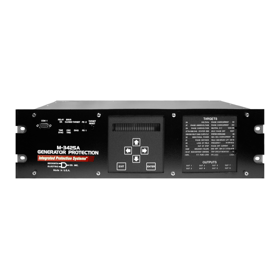
BECKWITH ELECTRIC M-3425A Instruction Book (482 pages)
Integrated Protection System for Generators of All Sizes
Brand:
BECKWITH ELECTRIC
| Category:
Protection Device
| Size: 9 MB
Table of Contents
This Page Left Intentionally Blank
44
M-3425A Generator Protection
26
Table of Contents
44
Chapter 1 Introduction
58
Instruction Book Contents
58
M-3425A Generator Protection Relay
59
Auto Calibration
59
Appendix A: Configuration Record Forms
59
Appendix B: Communications
59
Appendix C: Self-Test Error Codes
59
Appendix D: Inverse Time Curves
59
Appendix E: Layup and Storage
59
Appendix F: HMI Menu Flow
59
Appendix G: Index
59
Appendix H: Declaration of Conformity
59
Communication Ports
60
Accessories
61
M-3925A Target Module
61
M-3801D Ipsplot Plus Oscillograph Analysis Software
62
M-3931 Human-Machine Interface (HMI) Module
62
M-3933/M-0423 Serial Communications Cable
62
M-3948 Redundant High Voltage Power Supply
62
M-3949 Redundant Low Voltage Power Supply
62
S-3400 Ipscom Communications Software
61
Chapter 2 Operation
65
Alphanumeric Display
66
Arrow Pushbuttons
66
Breaker Closed (BRKR CLOSED) LED
66
Diagnostic LED (DIAG)
66
ENTER Pushbutton
66
EXIT Pushbutton
66
Front Panel Controls and Indicators
66
Relay Ok Led
66
Screen Blanking
66
Time Sync LED
66
M-3925A Target Module and Target Reset Pushbutton
67
Power Supply (PS1) and (PS2) Leds
67
Target LED
67
Default Message Screens
68
HMI Operation Overview
68
Operation (HMI/PC)
68
System Priority
68
HMI Security
69
Main HMI Menu Flow
70
Status Monitoring (from Relay Front Panel)
71
Primary Metering & Status
72
Status Monitoring (from Ipscom ® )
72
Primary Metering & Status Screen
73
Monitor/Secondary Metering and Status
74
Secondary Metering & Status
74
Secondary Metering & Status Screen
75
Time and Date Stamping
76
View Target History
76
View Target History (from Ipscom ® )
78
View Targets
78
View Targets Screen
78
Clear Targets
79
Oscillograph Recorder Data
79
Oscillograph Download Successful Confirmation Screen
82
Oscillograph Record Download Dialog Screen
82
Oscillograph Recorder (from Ipscom)
82
Retrieve Oscillograph Records
82
Clear Oscillograph Records
83
Clear Oscillograph Records Confirmation Screen
83
Oscillograph Records Successfully Cleared Dialog Screen
83
Oscillograph Successfully Triggered Dialog Screen
83
Trigger Oscillograph
83
Trigger Oscillograph Confirmation Screen
83
Serial Number (Relay Front Panel Only)
84
Software Version (Relay Front Panel Only)
84
Alter Access Codes (from Relay Front Panel)
85
Access Code Changed Confirmation Screen
87
Alter User Access Codes (from Ipscom ® )
87
Comm Access Codes
87
Access Level Code Dialog Screen
88
Change User Access Code Dialog Screen
88
User Access Codes
88
Clear Output Counters (Relay Front Panel)
89
System Error Codes, Output and Alarm Counters
89
Clear Alarm Counters (Relay Front Panel)
90
Clear Error Codes (Relay Front Panel)
91
Counters and Error Codes Dialog Screen
92
Resetting Counters (from Ipscom)
92
Tools/Counters and Error Codes
92
Relay/Sequence of Events/Retrieve
93
Sequence of Events Retrieve Download Screen
93
Time and Date Stamping
93
View Sequence of Events Record Screen
93
Clear Sequence of Events Record Command Confirmation Screen
94
Relay/Sequence of Events/Clear
94
Relay/Sequence of Events/View
94
Chapter 3 Ipscom
96
Ipscom Functional Description
96
Ipscom Main Screen Menu Bar
96
Ipscom Main Screen Status Line
96
Shortcut Command Buttons
96
File Menu
99
File/Close Command
99
File/Exit Command
99
File/New Command
99
File/Open Command
99
File/Save and Save as Command
99
Connect\Communication Menu
100
Communication\Open Terminal Window
101
Monitor Menu
102
Monitor/Primary Metering & Status
102
Monitor/Secondary Metering & Status
104
Monitor/Accumulator Status
106
Monitor/Phasor Diagram
107
Monitor/Phase Distance Diagram
108
Monitor/Loss of Field
109
Monitor/Out of Step
110
Monitor/Sync Scope
111
Monitor/Function Status
112
Monitor/87 Dual Slope
113
Relay Menu
114
Relay/Setup
114
Relay/Setup/Setup System
114
Relay/Setup/Relay Setpoints
116
Relay/Setup/Set Date & Time
118
Relay/Setup/Display/I/O Map
119
Relay/Setup/Display All Setpoints
120
Relay/Targets
121
Relay/Sequence of Events
122
Relay/Oscillograph
124
Relay/Profile
125
Relay/Read Data from Relay
126
Relay/Write File to Relay
126
Tools Menu
126
Tools/Security
126
Tools/Security/ Change Comm Access Code
126
System OK LED
127
Tools/Security/Change User Access Code
127
Tools/User Information
127
Tools/User Information/User Logo Line
127
User Control Number
127
Tools/Output Test
128
Tools/Relay Communication
128
Tools/Counters and Error Codes
129
Help Menu
130
Tools/Calibration Data
130
Tools/Firmware Update
130
Window Menu
130
Chapter 4 System Setup and Setpoints
132
Unit Setup
132
- System Setup and Setpoints
133
Chapter 4 - System Setup and Setpoints
136
HMI Comm Access Code Setup
136
Ipscom User Access Code Setup
137
HMI User Access Codes Setup
138
HMI User Logo Line Setup
139
Ipscom User Logo Line, User Control Number, System OK LED Setup and HMI Blanking
139
System OK LED
139
User Control Number
139
User Logo Line
139
HMI User Control Number Setup
141
HMI System OK LED Setup
142
HMI SET DATE and TIME
143
Direct Connection
145
Ipscom Set Date/Time
143
System Clock
143
Communication Setup
145
Device Address
145
Ipscom COM Port Definitions and System's Communication Address
145
Serial Port (RS-485)
145
Serial Ports (RS-232)
145
HMI COM Port Definitions and Device Address
147
COM Port Security
148
Disabling COM Ports
148
Ipscom Ethernet Port Setup with DHCP
149
DHCP Protocol
149
Ethernet Communication Settings
149
ETHERNET Protocols
149
Ipscom Ethernet Port Setup Without DHCP
149
HMI Ethernet Port Setup
150
Manual Configuration of Ethernet Board
151
Installing the Modems
152
Connecting the PC Modem
152
Initializing the PC Modem
153
Connecting the Local Modem to the Relay
154
Oscillograph Setup
155
Ipscom Setup Oscillograph Recorder
156
HMI Setup Oscillograph Recorder
157
Ipscom Setup Sequence of Events Recorder
158
Setup System
159
System Diagrams
164
System Setpoints
170
Setpoint Profiles (Setting Groups)
170
Configure Relay Data
170
Functions
171
Special Considerations
172
Phase Distance
177
Overexcitation Volts/Hz
181
M-3425A Firmware Version D-0150V 01.00.34
182
M-3425A Firmware Version D-0150V 01.04.00
182
Delta Voltage and Delta Frequency Check
184
Phase Angle Check
184
Sync Check
184
Phase Undervoltage
188
27TN #2 Screens Are Identical to 27TN #1
191
Directional Power
192
Protection from Excessive Reactive Power
192
Protection from Generator Motoring
192
Protection from Generator Overload
192
Loss of Field
196
Negative Sequence Overcurrent
199
Stator Overload Protection
201
50/50N Instantaneous Overcurrent, Phase and Neutral Circuits
204
50/50N Instantaneous Overcurrent
204
50BF Generator Breaker Failure/Hv Breaker Flashover
206
50DT Definite Time Overcurrent (for Split-Phase Differential)
208
50DT Definite Time Overcurrent
208
50/27 Inadvertent Energizing
209
Inverse Time Neutral Overcurrent
211
Inverse Time Phase Overcurrent with Voltage Control/Restraint
212
Inverse Time Phase Overcurrent with
212
Voltage Control/Restraint
212
Phase Overvoltage
214
Third Harmonic Voltage Differential (Ratio)
216
Overvoltage, Neutral Circuit or Zero Sequence
218
Multipurpose Overvoltage
220
60FL VT Fuse Loss
222
60FL VT Fuse Loss Alarm Function
222
Protection
222
External Fuse-Loss Function
222
Internal Fuse Loss Detection Logic
222
F Field Ground Protection
224
Factors Affecting 64F Performance
224
Field Ground Detection
224
Brush Lift-Off Detection
226
100% Stator Ground Protection by Low Frequency Signal Injection
228
Residual Directional Overcurrent
234
Out-Of-Step
237
Out-Of-Step
239
Frequency
240
Frequency Accumulator
243
Rate of Change of Frequency
245
Phase Differential
246
87GD Ground (Zero Sequence) Differential
248
Breaker Monitoring
249
Trip Circuit Monitoring
250
Ipslogic
251
Settings and Logic Applicable When Ipslogic™ Function(S) Programmed Using Ipscom
253
DO/RST (Dropout/Reset) Timer Feature
255
Dropout Delay Timer
255
Reset Delay Timer
255
Installation
256
Chapter 5 Installation
256
General Information
256
Service Conditions and Conformity to CE Standard
256
Mechanical/Physical Dimensions
257
External Connections
263
Grounding Requirements
263
Insulation Coordination
263
Power Supply
263
Relay Outputs
263
Replacement Fuses
263
Torque Requirements
263
Unit Isolation
263
Commissioning Checkout
269
Circuit Board Switches and Jumpers
275
Accessing Switches and Jumpers
275
Low Frequency Signal Injection Equipment
279
Ipscom ® Communications and Analysis Software Installation
285
Hardware Requirements
285
Installing Ipscom
285
Ipscom Installation and Setup
285
Activating Initial Local Communications
285
Ipscom
285
Initial Setup Procedure
286
6 Testing
288
Chapter 6 Testing
289
Equipment/Test Setup
289
Equipment Required
289
Setup
289
Functional Test Procedures
293
Power on Self Tests
294
Phase Distance
295
Directional Power, 3-Phase
308
Loss of Field
311
Negative Sequence Overcurrent Definite Time
313
Negative Sequence Overcurrent Inverse Time
314
Stator Overload
315
Instantaneous Phase Overcurrent
317
50BF/50BF-N Breaker Failure
318
50/27 Inadvertent Energizing
320
50DT Definite Time Overcurrent for Split-Phase Differential
321
Instantaneous Neutral Overcurrent
322
Inverse Time Neutral Overcurrent
323
Inverse Time Phase Overcurrent with Voltage Control/Restraint
324
Third Harmonic Voltage Differential
327
Overvoltage, Neutral Circuit or Zero Sequence
328
Multipurpose Overvoltage
329
60FL VT Fuse Loss Detection
330
Field Ground Protection
331
Brush Lift off Detection
333
Out of Step
341
Frequency
344
Rate of Change of Frequency
345
Phase Differential
347
87GD Ground Differential
349
Trip Circuit Monitoring
353
Ipslogic
354
Overview
355
Diagnostic Test Procedures
355
Button Test
360
Display Test
361
Auto Calibration
365
Auto-Calibration
365
Advertisement
BECKWITH ELECTRIC M-3425A Instruction Book (191 pages)
Generator Protection
Brand:
BECKWITH ELECTRIC
| Category:
Relays
| Size: 2 MB
Table of Contents
Printed in U.S.A. (9
29
Table of Contents
34
Chapters - Part 1 of
35
Appendix A: Configuration Record Forms
48
M-3425A Generator Protection Relay
49
Chapter 6 Testing (Cont'D)
48
Chapter 1 Introduction
48
Instruction Book Contents
48
Appendix B: Communications
49
Appendix C: Self-Test Error Codes
49
Accessories
51
Chapter 2 Application
52
Configuration
52
Relay Configuration Table
52
Functions
53
Profiles
53
Special Considerations
53
Relay System Setup
54
Setup System Dialog Box
56
Selection Screen for Expanded Input
57
System Diagrams
58
Three-Line Connection Diagram
60
Function 25 Sync Check Three-Line Connection Diagram
61
Function 59X Turn-To-Turn Fault Protection Three-Line Connection Diagram
62
Function 67N, 59D, 59X (Bus Ground) Three-Line Connection Diagram
63
Setpoints and Time Settings
64
Phase Distance
65
Phase Distance (21) Coverage
66
Phase Distance (21) Function Applied for System Backup
67
Phase Distance
68
Phase Distance (21) Setpoint Ranges
68
Overexcitation Volts/Hz
69
Example of Capability and Protection Curves (24)
70
Volts-Per-Hertz (24) Setpoint Ranges
71
Sync Check
72
Sync Check Logic Diagrams
74
Sync Check
75
Sync Check (25) Setpoint Ranges
75
Phase Undervoltage
76
27TN Third Harmonic Undervoltage, Neutral
77
Third-Harmonic Undervoltage (27TN) Protection Characteristics
78
TN Blocking Regions
79
Third Harmonic Undervoltage, Neutral Circuit (27TN Setpoint Ranges
80
Directional Power
81
Tripping on Overpower (over Power with Positive Pickup)
83
Tripping on over Reactive Power with
84
Directional Power, 3-Phase (32) Setpoint Ranges
85
Loss of Field
86
Voltage Control Time Settings
87
Loss of Field (40) Protective Approach 1
88
Loss of Field (40) Setpoint Ranges
89
Negative Sequence Overcurrent
90
Negative Sequence Overcurrent Inverse Time Curves
91
Stator Overload Protection
92
Function Overload Curves
93
Stator Thermal Protection (49) Setpoint Ranges
94
Instantaneous Overcurrent (50) Setpoint Ranges
95
Instantaneous Neutral Overcurrent (50N) Setpoint Ranges
96
50BF Generator Breaker Failure/Hv Breaker Flashover
97
Breaker Failure Logic Diagram
98
Breaker Failure (50BF) Setpoint Ranges
99
50DT Definite Time Overcurrent (for Split-Phase Differential)
100
50/27 Inadvertant Energizing
101
Inadvertent Energizing Function Logic Diagram
102
Inverse Time Neutral Overcurrent
103
Inverse Time Phase Overcurrent with Voltage Control/Restraint
104
Voltage Restraint (51VR) Characteristic
105
Phase Overvoltage
106
Third Harmonic Voltage Differential
107
Third Harmonic Voltage Differential (59D) Setpoint Ranges
108
Overvoltage, Neutral Circuit or Zero Sequence
109
Multipurpose Overvoltage (Turn-To-Turn Stator Fault or Bus Ground Protection)
110
Turn-To-Turn Stator Winding Fault Protection
110
60FL VT Fuse Loss
112
Fuse Loss (60FL) Setpoint Ranges
114
F Field Ground Protection
115
Field Ground Protection
115
Brush Lift-Off Detection
117
100% Stator Ground Protection by Low Frequency Signal Injection
118
S Function Component Connection Diagram
119
Stator Ground Protection (64S) Setpoint Ranges
120
Residual Directional Overcurrent
121
Residual Directional Overcurrent (67N) Setpoint Ranges
123
Out of Step
124
Out-Of-Step Relay Characteristics
125
Out-Of-Step (78) Setpoint Ranges
126
Frequency
127
Example of Frequency (81) Trip Characteristics
128
Frequency Accumulators
129
Frequency Accumulator (81A) Example Bands
130
Rate of Change of Frequency
131
Phase Differential
132
Differential Relay (87) Operating Characteristics
133
87GD Ground (Zero Sequence) Differential
134
Breaker Monitoring
135
Trip Circuit Monitoring
136
Trip Circuit Monitor (TC) Setpoint Ranges
137
Ipslogic
138
Ipslogic
140
Ipslogic Function Programming
140
Selection Screen for Initiating Function Timeout
141
Dropout Delay Timer Logic Diagram
142
Chapter 3 Operation
144
Front Panel Controls
144
Alphanumeric Display
144
Screen Blanking
144
Arrow Pushbuttons
144
Exit Pushbutton
144
Enter Pushbutton
144
Target & Status Indicators and Controls
144
Power Supply #1 (#2) LED
145
Relay OK LED
145
Breaker Closed LED
145
Target Indicators and Target Reset
145
Time Sync LED
145
Diagnostic LED
145
Accessing Screens
145
Default Message Screens
145
M-3425A Front Panel
146
Main Menu Flow
147
Initial Setup Procedure/Settings
148
Setup Unit Data
148
Setup Unit Data Entry
148
Setup Unit Features that Do Not Require Data Entry
149
Setup System Data
149
Configure Relay Data
150
Setpoints and Time Settings
150
Oscillograph Recorder Data
151
Communications Settings
151
Status/Metering
152
Target History
153
Phase Undervoltage
154
Chapter 4 Remote Operation
156
Remote Operation
156
Serial Ports (RS-232)
156
Serial Port (RS-485)
156
Optional Ethernet Port
156
Direct Connection
157
Setting up the M-3425A Generator Protection Relay for Communication
158
Serial Communication Settings
158
Ethernet Communication Settings
158
DHCP Protocol
158
Ethernet Protocols
158
Ethernet Port Setup
159
HMI Ethernet Port Setup
159
Manual Configuration of Ethernet Board
160
Ipsutil™ Ethernet Port Setup with DHCP
160
Ipsutil Ethernet Port Setup Without DHCP
160
Loss of Field
161
Installing the Modems
162
Installation and Setup
163
Operation
163
Activating Communications
163
Overview
164
File Menu
164
Comm Menu
164
Relay Menu
165
Setup System Dialog Box
166
Expanded Input Active State
167
Relay Setpoints Dialog Box
168
All Setpoints Table Dialog Box (Partial)
169
Configure Dialog Box (Partial)
170
Unit Date/Time Dialog Box
172
Target Dialog Box
173
Trigger Events Screen with Expanded I/O
174
Event Download Screen
175
Window Menu/Help Menu
176
Checkout Status/Metering
177
Accumulator Status Screen
178
Loss of Field Dialog Box
179
Phasor Dialog Box
180
Function Status Screen
181
Cautions
182
Keyboard Shortcuts
183
Ipsutil Communications Software
184
M-3890 Ipsutil
184
Installation and Setup
184
Installation
185
System Setup
185
Overview
185
Comm Menu
185
Relay Comm Command
185
Ethernet Command
185
Clock Command
185
Security Menu
186
Miscellaneous Menu
186
Help Menu
187
Change Communication Access Code Dialog Box
188
BECKWITH ELECTRIC M-3425A Instruction Book (237 pages)
Generator Protection
Brand:
BECKWITH ELECTRIC
| Category:
Protection Device
| Size: 4 MB
Table of Contents
Table of Contents
86
Equipment/Test Setup
87
Functional Test Procedures
91
Power on Selftests
92
Phase Distance
93
Directional Power, 3-Phase
106
Loss of Field
109
Stator Overload
113
Instantaneous Phase Overcurrent
115
50BF/50BF-N Breaker Failure
116
50/27 Inadvertent Energizing
118
50DT Definite Time Overcurrent for
119
Instantaneous Neutral Overcurrent
120
Inverse Time Neutral Overcurrent
121
Inverse Time Phase Overcurrent with Voltage Control/Restraint
122
Third Harmonic Voltage Differential
125
Overvoltage, Neutral Circuit or Zero Sequence
126
Multipurpose Overvoltage
127
60FL VT Fuse Loss Detection
128
Field Ground Protection
129
Brush Lift off Detection
131
Out of Step
138
Frequency
140
Frequency Accumulator
141
Rate of Change of Frequency
142
Phase Differential
144
87GD Ground Differential
146
Breaker Monitoring
148
Trip Circuit Monitoring
150
Ipslogic
151
Diagnostic Test Procedures
152
Auto-Calibration
162
Advertisement
Advertisement
Related Products
BECKWITH ELECTRIC M-3425
BECKWITH ELECTRIC M-0329B
BECKWITH ELECTRIC Syncrocloser M-3410A
BECKWITH ELECTRIC M?3311A
BECKWITH ELECTRIC M-3520
BECKWITH ELECTRIC M-2601
BECKWITH ELECTRIC M-6280A
BECKWITH ELECTRIC M-7679
BECKWITH ELECTRIC M-0194
BECKWITH ELECTRIC M-0215
BECKWITH ELECTRIC Categories
Relays
Controller
Transceiver
Protection Device
Control Systems
More BECKWITH ELECTRIC Manuals
Login
Sign In
OR
Sign in with Facebook
Sign in with Google
Upload manual
Upload from disk
Upload from URL