Table of Contents
Advertisement
Quick Links
Advertisement
Table of Contents

Related Manuals for BECKWITH ELECTRIC M-3410A


Summary of Contents for BECKWITH ELECTRIC M-3410A
- Page 1 Instruction Book M-3410A Intertie/Generator Protection Relay...
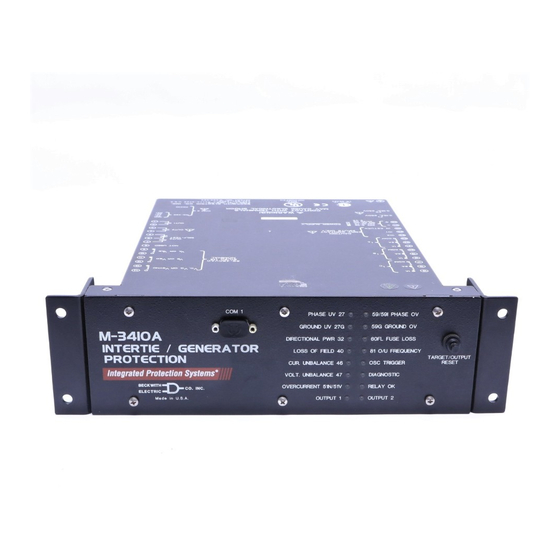
- Page 2 EL EC T RIC EL EC T RIC Ma d e in U.S .A . Ma d e in U.S .A . M-3410A Standard Panel M-3410A Vertical Panel (Optional) COM 1 PHASE UV 27 59/59I PHASE OV 59G GROUND OV...
- Page 3 M-3410A Intertie/Generator Protection Relay Protective Functions • Sync-check with Phase Angle, ΔV and ΔF with dead line/dead bus options (25) • Phase undervoltage (27) protection • Ground undervoltage (27G) protection • Dual-setpoint, single or three phase, directional power detection that can be selected as over/ under power protection (32) •...
- Page 4 M-3410A Intertie/Generator Protection Relay PROTECTIVE FUNCTIONS PROTECTIVE FUNCTIONS PROTECTIVE FUNCTIONS PROTECTIVE FUNCTIONS PROTECTIVE FUNCTIONS Device Device Setpoint Setpoint Device Device Device Setpoint Setpoint Setpoint Number Number Number Function Function Function Ranges Ranges Ranges Increment Increment Increment Accuracy Accuracy Accuracy Number...
- Page 5 M-3410A Intertie/Generator Protection Relay PROTECTIVE FUNCTIONS ( PROTECTIVE FUNCTIONS ( PROTECTIVE FUNCTIONS ( PROTECTIVE FUNCTIONS ( PROTECTIVE FUNCTIONS ( cont cont cont cont .) .) .) .) .) cont Device Device Device Device Device Setpoint Setpoint Setpoint Setpoint Setpoint Number...
- Page 6 M-3410A Intertie/Generator Protection Relay PROTECTIVE FUNCTIONS ( PROTECTIVE FUNCTIONS ( PROTECTIVE FUNCTIONS ( PROTECTIVE FUNCTIONS ( PROTECTIVE FUNCTIONS ( cont cont cont cont .) .) .) .) .) cont Device Device Device Device Device Setpoint Setpoint Setpoint Setpoint Setpoint Number...
- Page 7 M-3410A Intertie/Generator Protection Relay PROTECTIVE FUNCTIONS ( PROTECTIVE FUNCTIONS ( PROTECTIVE FUNCTIONS ( PROTECTIVE FUNCTIONS ( PROTECTIVE FUNCTIONS ( cont cont cont cont .) .) .) .) .) cont Device Device Device Device Device Setpoint Setpoint Setpoint Setpoint Setpoint Number...
- Page 8 M-3410A Intertie/Generator Protection Relay Description The M-3410A Intertie/Generator Protection Relay is intended for the protection of the intertie between the utility and dispersed generation. It is also suitable for the protection of synchronous and induction generators. Communications and control features of the M-3410A are accomplished utilizing the M-3810A ®...
- Page 9 0.3 VA at 1 A for 1 A inputs. Control/Status Inputs The control/status inputs, INPUT1 and INPUT2, can be programmed to block any of the M-3410A functions and trigger the oscillograph recorder. The control/status inputs accept only dry contacts and are internally wetted (9 V dc) by the relay's power supply.
- Page 10 M-3410A Intertie/Generator Protection Relay Tests and Standards Tests and Standards Tests and Standards Tests and Standards Tests and Standards The M-3410A Generator/Intertie Protection Relay complies with the following type tests and standards: Voltage Withstand Voltage Withstand Voltage Withstand Voltage Withstand Voltage Withstand...
- Page 11 M-3410A Intertie/Generator Protection Relay Radiated Susceptibility ANSI/IEEE 25-1000 Mhz @ 35V/m C37.90.2 1995 Output Contacts ANSI/IEEE Make 30 A for 0.2 seconds, off for 15 seconds for 2,000 operations C37.90.0 Section 6.7.1, Tripping Output Performance Requirements 1989 Atmospheric Environment Atmospheric Environment...
- Page 12 Patent & Warranty The M-3410A Generator/Intertie Protection Relay is covered by U.S. Patent 5,592,393. The M-3410A Generator/Intertie Protection Relay is covered by a five year warranty from date of shipment. External Connections M-3410A external connection points are illustrated in Figure 1, Standard Panel Layout External Connections and Figure 2 for the optional Horizontal and Vertical Panel External Connection Layouts.
- Page 13 See M-3410A Instruction Book, Section 2.3, External Connections. See M-3410A Instruction Book, Section 3.1, Relay Configuration, Output Contact Mode. See M-3410A Instruction Book, Section 2.9, Relay Remote Communication Setup (PC), COM2 Configuration. See M-3410A Instruction Book, Section 2.3, External Connections.
- Page 14 See M-3410A Instruction Book, Section 2.3, External Connections. See M-3410A Instruction Book, Section 3.1, Relay Configuration, Output Contact Mode. See M-3410A Instruction Book, Section 2.9, Relay Remote Communication Setup (PC), COM2 Configuration. See M-3410A Instruction Book, Section 2.3, External Connections.
- Page 15 M-3410A Intertie/Generator Protection Relay Utility System M-3410A Generator Protection Programmable I/O LED Targets Power Metering Sequence of Events Logging Waveform Capture (COMTRADE) User Interface with PC Communications 60FL VTs are not necessary if generator rated voltage is < 480 V ac.
- Page 16 M-3410A Intertie/Generator Protection Relay Utility System M-3410A Intertie Protection Programmable I/O LED Targets Metering Sequence of Events Logging Waveform Capture (COMTRADE) User Interface with PC 60FL Communications Power VTs are not necessary if the Rated Nominal Interconnection Voltage is < 480 V ac.
- Page 17 M-3410A Intertie/Generator Protection Relay M-3410A Typical Connection Diagram Voltage Inputs for 25 function can only M-3410A be used in line-line VT configuration. M-3410A Power M-3410A Alternate VT connection, phase voltages CT Configuration CT Configuration Alternate VT connection M-3410A M-3410A for sync voltage...
- Page 18 M-3410A Intertie/Generator Protection Relay M-3410A Typical Connection Diagram M-3410A Alternate VT connections, phase M-3410A voltage Alternate VT connection or sync voltage CT Configuration CT Configuration VTs are not necessary if the M-3410A M-3410A Nominal Rated Interconnection Voltage is < 480 V ac.
- Page 19 M-3410A Intertie/Generator Protection Relay 12.50 [317.50] 0.38 11.75 0.05 [9.53] [298.45] [0.13] 0.48 [12.19] COM 1 PHASE UV 27 59/59I PHASE OV 59G GROUND OV GROUND UV 27G DIRECTIONAL PWR 32 60FL FUSE LOSS INTERTIE / GENERATOR 3.56 3.46 LOSS OF FIELD 40 81 O/U FREQUENCY 2.50...
- Page 20 M-3410A Intertie/Generator Protection Relay 19.00 [482.60] 18.25 [463.55] 0.05 [0.13] REF COM 1 PHASE UV 27 59/59I PHASE OV 59G GROUND OV GROUND UV 27G M-3410A DIRECTIONAL PWR 32 60FL FUSE LOSS INTERTIE / GENERATOR 2.50 3.46 3.56 LOSS OF FIELD 40...
- Page 21 M-3410A Intertie/Generator Protection Relay 12.000 [304.80] 0.312 1.688 8.000 [203.20] 2.500 [63.50] [42.88] [7.92] 0.600 [15.24] COM 1 1.788 [45.42] PHASE UNDERVOLTAGE 27 59/59I PHASE OVERVOLTAGE GROUND UNDERVOLTAGE 27G 59G GROUND OVERVOLTAGE DIRECTIONAL PWR 32 60FL FUSE LOSS 12.200 LOSS OF FIELD 40 81 OVER/UNDER FREQUENCY [309.88]...
- Page 22 M-3410A Intertie/Generator Protection Relay 1 0.00 [304.80] 0 0.31 [7.92] 8.00 0 1.69 0 2.98 [203.20 [42.88 [7.57] 0 1.79 COM 1 PHASE UV 27 59/59I PHASE OV [45.42] GROUND UV 27G 59G GROUND OV DIRECTIONAL PWR 32 60FL FUSE LOSS...
- Page 23 BECKWITH ELECTRIC CO., INC. 6190 - 118th Avenue North • Largo, Florida 33773-3724 U.S.A. PHONE (727) 544-2326 • FAX (727) 546-0121 E-MAIL marketing@beckwithelectric.com WEB PAGE www.beckwithelectric.com © 2001 Beckwith Electric Co. 800-3410A-SP-03 10/07 Printed in U.S.A. (11.26.02)
- Page 24 WARNING DANGEROUS VOLTAGES, capable of causing death or serious injury, are present on the external terminals and inside the equip- ment. Use extreme caution and follow all safety rules when han- dling, testing or adjusting the equipment. However, these internal voltage levels are no greater than the voltages applied to the exter- nal terminals.
- Page 25 PRODUCT CAUTIONS Before attempting any test, calibration, or maintenance procedure, personnel must be completely familiar with the particular circuitry of this unit, and have an adequate understanding of field effect devices. If a component is found to be defective, always follow replacement procedures carefully to that assure safety features are maintained.
-
Page 26: Table Of Contents
M-3410A Intertie/Generator Protection Relay ..............2 Generator Protection ......................2 Intertie Protection ......................... 2 Single Phase Application Considerations ................3 Table 1-1 M-3410A Intertie Protection Functions ............. 3 Table 1-2 M-3410A Generator Protection Functions ............3 Singlephase Threewire ......................4 Single-phase Two-wire ......................4 Alternate Singlephase Twowire .................... - Page 27 M-3410A Instruction Book External Connections ......................5 Grounding Requirements ...................... 5 Figure 2-5 Output Relay Actuation Setting ................ 5 Unit Isolation ......................... 5 Insulation Coordination ......................5 Torque Requirements ......................5 Relay Outputs ........................5 Replacement Fuses ......................5 Figure 2-6 External Connections ..................6 Figure 2-7 Optional Horizontal and Vertical Panel External Connection Layout .....
- Page 28 Table of Contents Relay Remote Communication Setup (PC) ............... 21 Overview ..........................21 Communication Protocol ....................21 Figure 2-22 Multiple System Addressing Using Communications-Line Splitter ..... 21 Multiple System Application ....................21 Serial Multidrop Network Application ................. 21 Installing the Modems ......................22 Activating Communications....................
- Page 29 M-3410A Instruction Book ® Figure 3-7 M-3810A IPScom for Windows Setup Event Recorder Trigger Dialog Box ..........................6 ® ® Figure 3-8 M-3811A IPScom for Palm OS Setup Event Recorder Dialog Screen #1 ........................7 Figure 3-9 M-3811A IPScom for Palm OS Setup Event Recorder Dialog Screen #2 ........................
- Page 30 Table of Contents Figure 3-25 M-3811A IPScom for Palm OS (59G) Ground Overvoltage Setup Dialog Screen ......................19 32 Directional Power, 3-Phase or 1-Phase ..............20 Configuration Process ......................20 Figure 3-26 Directional Power Configurations ..............21 ® ® Figure 3-28 M-3811A IPScom for Palm OS (32) Directional Power Setup Dialog Screen ......................
- Page 31 M-3410A Instruction Book 60FL VT Fuse Loss ......................42 ® Figure 3-47 M-3810A IPScom for Windows™ (60FL) Fuse Loss Setup Dialog Screen ......................42 ® ® Figure 3-48 M-3811A IPScom for Palm OS (60FL) Fuse Loss Setup Dialog Screen ......................43 79 Reconnect Enable Time Delay ..................
- Page 32 Table of Contents Tools Menu ......................... 12 Access Code Submenu ..................... 12 ® Table 4-1 M-3810A IPScom for Windows™ User Access Code Level Privileges..12 ® Figure 4-13 M-3810A IPScom for Windows™ Comm Access Code Reset ....13 Figure 4-14 M-3810A IPScom for Windows User Access Code Reset ......13 Diagnostics Command .......................
- Page 33 Figure 4-38 M-3811A IPScom for Palm OS User Access Level Code ......23 M-3811A/Handheld Database/Record Structure ..............24 Figure 4-39 M-3410A/Handheld Data Flow ..............24 Upload & Download ......................25 Figure 4-40 M-3811A IPScom for Palm OS Upload Dialog Screen ......25 Figure 4-41 M-3811A IPScom for Palm OS Receive Confirmation Screen ....
- Page 34 Table of Contents Figure 4-67 M-3811A IPScom for Palm OS Oscillograph Retrieval Confirmation Screen ......................30 Monitor/Recorder/Clear Oscillograph ................. 30 Figure 4-68 M-3811A IPScom for Palm OS Clear Oscillograph Dialog Screen ... 30 Figure 4-69 M-3811A IPScom for Palm OS Clear Oscillograph Command Sent Confirmation Screen ................
- Page 35 System and IPScom Compatibility ................... 38 Time and Date Stamping ....................38 Echo Cancel ........................38 Serial Port Connections ..................... 38 M-3410A Battery Replacement ..................39 Chapter 5 Testing Equipment/Test Setup ......................2 Equipment Required ......................2 Table 5-1 Functions to Disable When Testing ..............2 Setup .............................
- Page 36 Table of Contents Diagnostic Test Procedures ....................4 Output Test (Relay) ......................4 Table 5-2 Output Contacts ....................4 Control/Status Input Test ..................... 4 Table 5-3 Control/Status Inputs ..................4 Output Test (Self-Test Relay)....................4 Table 5-4 Self-Test Ouput Contacts ................. 4 Target LED Test ........................
- Page 37 M-3410A Instruction Book Appendix A - Configuration Record Forms Configuration Record Forms ....................1 Table A-1 Relay Configuration Table ................2 PC COM1 Setup ........................3 PC COM2 Setup ........................3 PC COM3 Setup ........................3 Communication Address ...................... 3 Table A-2 Communication Data &...
- Page 38 Table C-1 Self-Test Error Codes ..................1 Table C-1 Self-Test Error Codes (continued)..............2 Appendix D - Inverse Time Curves Table D-1A M-3410A Inverse Time Overcurrent Relay Characteristic Curves (1 of 2) ..................... 2 Table D-1B M-3410A Inverse Time Overcurrent Relay Characteristic Curves (2 of 2) .....................
- Page 39 M-3410A Instruction Book This Page Left Intentionally Blank...
-
Page 40: Chapter 1 Introduction
Chapter 4: Operation and Interface Chapter Two is designed for the person or group This chapter is designed for the person or group responsible for the installation of the M-3410A responsible for relay operation and interface Intertie/Generator Protection Relay. It includes the maintenance. -
Page 41: Appendix C: Self-Test Error Codes
Appendix E: Declaration of Conformity follows the standards of ANSI/IEEE Std. This Appendix lists those European standards which C37.2-1991, Standard Electric Power Systems the M-3410A Intertie/Generator Protection Relay Device Function Numbers. meets or exceeds. Two control/status inputs can be programmed to... -
Page 42: Single Phase Application Considerations
M-3410A relay. In either case, the core the generator is at its nameplate rating. These functions normally required by utilities and state calculations must include the ratio of the current interconnection documents operate normally. -
Page 43: Singlephase Threewire
(HMI) to the The second type of single-phase application is the M-3410A Relay. IPScom for Palm OS includes all 120 or 240 volts to ground. The wiring for this major IPScom features to support local HMI installation is shown in Figure 2-13. -
Page 44: General Information
Dimensions • 5° to 40° Centigrade • Maximum relative humidity 80% for Figures 2-1 through 2-5, M-3410A Mounting temperatures up to 31° C, decreasing in a Dimensions, contain physical dimensions of the linear manner to 50% relative humidity at relay that may be required for mounting the unit. - Page 45 INTERTIE / GENERATOR PROTECTION TARGET/OUTPUT RESET BECKW IT H C O. INC . EL EC T RIC Ma d e in U.S .A . 1.788 [45.42] 0.625 10.750 [273.05] CUTOUT [15.87] \U+22050.280 [\U+22057.11] Figure 2-1 M-3410A Standard Mounting Dimensions 2–2...
- Page 46 Installation – 2 12.50 [317.50] 0.38 11.75 0.05 [9.53] [298.45] [0.13] 0.48 [12.19] COM 1 PHASE UV 27 59/59I PHASE OV 59G GROUND OV GROUND UV 27G DIRECTIONAL PWR 32 60FL FUSE LOSS 3.56 INTERTIE / GENERATOR 3.46 LOSS OF FIELD 40 81 O/U FREQUENCY 2.50 PROTECTION...
- Page 47 M-3410A Instruction Book 19.00 [482.60] 18.25 [463.55] 0.05 [0.13] REF COM 1 PHASE UV 27 59/59I PHASE OV GROUND UV 27G 59G GROUND OV M-3410A DIRECTIONAL PWR 32 60FL FUSE LOSS INTERTIE / GENERATOR 2.50 3.46 3.56 LOSS OF FIELD 40...
- Page 48 COM 2 VOLT. UNBALANCE 47 DIAGNOSTIC 3.15A, 250A OVERCURRENT 51N/51V RELAY OK RS-485 OUTPUT 1 3.15A, 250A OUTPUT 2 POWER SUPPLY 9-36 M-3410A 36-75 85-150 INTERTIE / GENERATOR OUT1 50/60 HZ 5 VA PROTECTION IN RET URN OUT2 CAUTION 1 0.20...
-
Page 49: External Connections
A switch or circuit breaker for the M-3410A's power anytime external connections have been made shall be included in the building installation, and shall to the unit. - Page 50 Installation – 2 W A RNING! CONTACT WITH TERMINALS MAY CAUSE ELECTRICAL SHOCK RS232 COM 2 3.15A, 250V RS-485 3.15A, 250V B1 Option B2 Option B3 Option POWER SUPPLY 9-36 36-75 OUT1 OUT1 OUT1 85-150 50/60 HZ 5 VA IN RET URN OUT2 OUT2 CAUTION...
- Page 51 M-3410A Instruction Book C OR SYNC 69-480VAC 50/60 HZ B OR NOMINAL A OR NOT USED OUT3 SELF-TEST CAUTION B3 Option B2 Option B1 Option DRY CONTACT INPUTS ONLY OUT2 OUT2 OUT2 IN RET URN 9-36 POWER SUPPLY 36-75 OUT1...
- Page 52 Installation – 2 Utility System M-3410A Generator Protection Programmable I/O LED Targets Power Metering Sequence of Events Logging Waveform Capture (COMTRADE) User Interface with PC Communications 60FL VTs are not necessary if generator rated voltage is < 480 V ac.
- Page 53 M-3410A Instruction Book Utility System M-3410A Intertie Protection Programmable I/O LED Targets Metering Sequence of Events Logging Waveform Capture (COMTRADE) User Interface with PC 60FL Communications Power VTs are not necessary if the Rated Nominal Interconnection Voltage is < 480 V ac.
- Page 54 Installation – 2 M-3410A Typical Connection Diagram Voltage Inputs for 25 function can only M-3410A be used in line-line VT configuration. M-3410A Power M-3410A Alternate VT connection, phase voltages CT Configuration CT Configuration Alternate VT connection M-3410A M-3410A for sync voltage...
- Page 55 M-3410A Instruction Book M-3410A Typical Connection Diagram M-3410A Alternate VT connections, phase M-3410A voltage Alternate VT connection, ground or sync voltage CT Configuration CT Configuration VTs are not necessary if the M-3410A M-3410A Nominal Rated Interconnection Voltage is < 480 V ac.
- Page 56 Installation – 2 M-3410A Typical Single-Phase Three-Wire Connection Diagram CT Configuration CT Configuration M-3410A M-3410A M-3410A Setup Relay: Nominal Voltage (V ) : V or V or 1/2 V Nominal Current (I ) : I /CT Ratio or I /CT Ratio...
- Page 57 M-3410A Instruction Book M-3410A Typical Single-Phase Two-Wire Connection Diagram CT Configuration CT Configuration M-3410A M-3410A M-3410A Setup Relay: Nominal Voltage (V ) : V Nominal Current (I ) : I /CT Ratio VT Configuration : Line-to-Ground Monitor (Power): Primary Status : Actual Power...
- Page 58 Installation – 2 M-3410A Alternate Single-Phase Two-Wire Connection Diagram CT Configuration CT Configuration M-3410A M-3410A M-3410A Setup Relay: Nominal Voltage (V ) : V Nominal Current (I ) : I /CT Ratio VT Configuration : Line-to-Ground Monitor (Power): Primary Status : 3.0 X Actual Power...
-
Page 59: Ipscom Communications Software
Palm OS ® Communications Software provides • available for download from our website only local communication with the M-3410A. IPScom at www.beckwithelectric.com for Palm OS provides all IPScom features with the The M-3810A IPScom for Windows Communications exception of Calibration, Relay Software Update,... -
Page 60: M-3811A Ipscom For Palm Os Installation And Setup
Installation – 2 The installation utility establishes a program folder (Becoware) and ® subdirectory (IPScom ). The default location for the application files is on drive C:, in the new subdirectory "IPScom" (C:\Program Files\Becoware\ IPScom\M-3810A). After installation, the Figure 2-17 HotSync Icon IPScom program icon (located in the Becoware directory) can be placed on M-3811A IPScom for Palm OS (PC) -
Page 61: Ipscom Communications Setup
NOTE: This instruction addresses the initial Verify the target Handheld is mounted in communication between IPScom and the cradle. the M-3410A. Therefore, factory default Initiate HotSync by selecting the values are given in parentheses. HotSync button on the cradle. • PC Port (IPScom for Windows) - Page 62 Installation – 2 Communication Figure 2-19 M-3810A IPScom ® for Windows™ Communication Dialog Box 2–19...
-
Page 63: Commissioning Checkout
M-3410A Instruction Book The positive sequence current should Commissioning Checkout be I The zero sequence current should be During field commissioning, check the following to y0A. If a significant amount of ZERO ensure that the CT and VT connections are correct. -
Page 64: Secondary Status Screen #1
Installation – 2 Secondary Status ® Figure 2-20 M-3810A IPScom for Windows™ Secondary Status Screen Secondary Status Voltage (V): Current (A): 0.00 0.00 0.00 + Seq: + Seq: - Seq: - Seq: 0 Seq: 0 Seq: sync ® Figure 2-21 M-3811A IPScom for Palm OS Secondary Status Screen #1 Secondary Status Peak Voltage (PU):... -
Page 65: Relay Remote Communication Setup (Pc)
M-3810A IPScom for Windows™ Communications Multiple System Application Software provides remote communication with one or more M-3410A Intertie/Generator Protection The individual addressing capability of IPScom and Relays. This section contains the information the relay allows multiple systems to share a direct... -
Page 66: Installing The Modems
An Application Note, “ Serial Communication with relay involves programming the Beckwith Electric’s Integrated Protection System parameters (using the AT command set), Relays ” is available by contacting Beckwith Electric and storing this profile in the modem's Co., Inc., at www.beckwithelectric.com. nonvolatile memory. -
Page 67: Activating Communications
Jumpers M-3810A IPScom ® for Windows™ configured, communication with the M-3410A is activated as See Figure 2-25, M-3410A I/O Board, or Figure follows: 2-26, M-3410A Top-View CPU Board for Jumper Choose the IPScom for Windows icon locations. from the Becoware folder. -
Page 68: Factory Default Reset
Factory Default Reset CT circuits should be shorted prior to To reset all function settings to factory defaults, disconnecting CT wiring to the M-3410A. Death or perform the following: severe electrical shock can occur. 8 WARNING: Operating personnel must not ▲... - Page 69 CO. INC. ELECTRIC P-1861 BE# 450-00209 TP10 FB23 FB24 TP11 C123 C91 C90 TP12 FB25 FB26 To S1 FB27 on Fr Panel FB29 FB30 Figure 2-24 M-3410A IO Board JP19 JP18 JP21 Figure 2-25 M-3410A Top-View CPU Board JP21 2–26...
- Page 70 Installation – 2 TP1A JP13 JP14 JP13 JP12 JP12 JP11 JP11 SILKSCREEN SOLDER SIDE Figure 2-26 M-3410A Bottom-View CPU Board 2–27...
- Page 71 M-3410A Instruction Book This Page Left Intentionally Blank 2–28...
-
Page 72: Chapter 3 Configuration And Settings
Setpoints and Time Settings ............. 3–8 Chapter Three is designed for the person or group Enabling a relay protective function consists of responsible for the configuration of the M-3410A entering the required settings in the individual Intertie/Generator Protection Relay. This chapter function screens. -
Page 73: Relay Setup
M-3410A Instruction Book Relay Setup Configuration Menu. Regardless of the functions enabled or disabled, all information shown is The relay setup consists of defining all pertinent required. Several functions require the proper setting information regarding certain relay actions and of these values for correct operation. The Nominal system quantities. - Page 74 Control Number: 0 Receive This command reads the individual User Logo: Beckwith Electric Co. setpoint/setting from the relay into the M-3410 handheld edit buffer. The difference between the Receive command and the...
-
Page 75: Nominal Frequency
The latch condition is maintained as long as power Phase Rotation is applied to the relay. This function allows the user to select the phase rotation of the M-3410A to match that of the power system (ABC or ACB). 3–4... -
Page 76: Ratio Of The Phase Vts/Cts
Configuration and Settings – 3 Ratio of the Phase VTs/CTs The snapshot of the waveform is stored in memory for later retrieval using IPScom These ratios are used to calculate the primary Communications Software. If additional values displayed in the Primary Status Screen events or triggers occur before Box, See Figure 4-25, Primary Status Dialog Box downloading, and the number of events... -
Page 77: Event Recorder Setup
Event Recorder Setup Oscillograph The event recorder is designed to record sequence Number of records: of events in the M-3410A relay. A total of 32 events can be recorded. After 32 events have been Post trigger delay: 5 (5 to 95%) recorded the earliest events will be overwritten with new events (FIFO). - Page 78 Configuration and Settings – 3 Event Event Function Pickup Timeout Dropout Normal operation Mode 1 Events are only stored Mode 2 if they are associated with an output contact operation 60FL Inputs Active Inactive 81#1 81#2 81#3 81#4 Figure 3-8 M-3811A IPScom ®...
-
Page 79: Setpoints And Time Settings
M-3410A Instruction Book voltage check will compare the absolute difference Setpoints and Time Settings between the selected sync phase voltage (V1) and the measured DG voltage (V2) with the Delta Volt limit setting. Likewise, the delta frequency measures The individual protective functions, along with their... - Page 80 Configuration and Settings – 3 Delta V and Delta F Check Logic With Delta V AND Delta F Enabled* |V 1 - V 2 | < Delta V Limit * Only one Delta V and Delta F Check Scheme Delta V Is Enabled may be enabled at a time.
- Page 81 M-3410A Instruction Book Sync Check (25) Function Logic Phase Angle, Delta V and Delta F Logic Dead Line/Dead Bus Logic From Sync Figure 3-12 Check Dead Line/Dead Bus Timer Dead Check Input Initiate Logic Check Timer Output Seal In Timer...
- Page 82 Configuration and Settings – 3 (25) Sync Check Figure 3-14 M-3810A IPScom ® for Windows™ 25 Sync Check Setup Dialog Screen Path: Relay/Setup/Setpoints/25 Sync Check COMMANDS Send Sends all entered information to the control. Cancel Returns you to the previous window; any changes to displayed information are lost. 3–11...
- Page 83 M-3410A Instruction Book Sync Check 25 Enable Disable Ph Angle Window: 90 (0 - 90 deg) Up V Lmt: 110.0 (100.0 - 120.0 %) Lo V Lmt: 90.0 (70.0 - 100.0 %) Sync Delay: 30 (1 - 8160 cyc) Dead V Lmt: 33.3 (0.0 - 50.0 %)
- Page 84 Configuration and Settings – 3 COMMANDS: SYNC CHECK 25/ACTION/... Sync Check 25 Send This command sends the individual Dead Input Initiate: ! 2 setpoint/setting contained in the Outputs: ! 2 Handheld edit buffer to the relay. The Blocking Inputs: ! 2 ! FL difference between the Send command and the Download command is that the...
-
Page 85: Phase Undervoltage, 3-Phase
M-3410A Instruction Book 27 Phase Undervoltage, 3-Phase Intertie Protection : Voltage is commonly suggested as an efficient means to protect against islanding. Generator Protection : The Undervoltage function Notably, unless the Dispersed Generation (DG) (27) may be used to detect any condition causing includes very high-speed generator excitation long- or short-term undervoltage. - Page 86 Configuration and Settings – 3 COMMANDS: UNDERVOLTAGE 27/ACTION/... Undervoltage 27 Send This command sends the individual Enable Disable setpoint/setting contained in the Handheld edit buffer to the relay. The Pickup: 90 (4.0 to 100.0 %) difference between the Send command and the Download command is that the Delay: 60.0 (1 to 8160 cycles)
-
Page 87: 59G Undervoltage/Overvoltage, Ground Circuit Or Zero Sequence
M-3410A Instruction Book 27G/59G Undervoltage/Overvoltage, Ground Ground Fault Detection Using One Phase-to- Circuit or Zero Sequence Ground VT and 59G/27G ▲ CAUTION: This scheme should be used with The Ground Circuit Under/Overvoltage functions (27G/59G) provide protection for ground faults on caution, since it can result in high overvoltages due systems supplied from an ungrounded source. - Page 88 Configuration and Settings – 3 To Dispersed Storage and Generation (DSG) To Utility Power Transformer Resistor Figure 3-20 Ground Fault Detection Using a Broken-Delta VT and 59G To Dispersed Storage and Generation (DSG) To Utility V L-L Power Transformer Fault on phase 'a' V = 0 Fault on phase 'b' or 'c' 27G detects Undervoltage V = V...
- Page 89 M-3410A Instruction Book (27G) Ground Undervoltage Figure 3-22 M-3810A IPScom ® for Windows™ (27G) Ground Undervoltage Setup Dialog Screen (59G) Ground Overvoltage Figure 3-23 M-3810A IPScom for Windows (59G) Ground Overvoltage Setup Dialog Screen Path: Relay/Setup/Setpoints/27G Ground Unvdervoltage or 59G Ground Overvoltage...
- Page 90 Configuration and Settings – 3 COMMANDS: GROUND UNDERVOLTAGE 27G OR Ground Undervoltage 27G GROUND OVERVOLTAGE 59G/ACTION/... Enable Disable Send This command sends the individual Pickup: 90 (4.0 to 100.0 %) setpoint/setting contained in the Handheld edit buffer to the relay. The Delay: 60 (1 to 8160 cycles) difference between the Send command...
-
Page 91: Directional Power, 3-Phase Or 1-Phase
Reverse Underpower Mode – A three-phase power measurements. When Three- decrease in reverse power flow that Phase Detect is disabled, the M-3410A detects the is below the pick up value will cause power in each phase, and operates if the power in a trip. - Page 92 Configuration and Settings – 3 32 #1 & #2 Delay – Power relays should be applied with a time delay to prevent mis-operation during power swing, heavy load pick up or heavy load rejection conditions. 32 Underpower – The 32 function must be blocked by breaker position through auxiliary contacts when the breaker is open.
- Page 93 M-3410A Instruction Book (32) Directional Power Figure 3-27 M-3810A IPScom ® for Windows™ (32) Directional Power Setup Dialog Screen Path: Relay/Setup/Setpoints/32 Directional Power COMMAND BUTTONS Save Saves all entered information to the control. Cancel Returns you to the previous window; any changes to displayed information are lost.
- Page 94 Configuration and Settings – 3 COMMANDS: DIRECTIONAL POWER 32/ACTION/... Directional Power 32 Send This command sends the individual Enable Disable setpoint/setting contained in the Handheld edit buffer to the relay. The Pickup: G0.02 (G3.00 to 3.00 PU) difference between the Send command and the Download command is that the Delay: 60 (1 to 8160 cycles)
-
Page 95: Loss Of Field (Generator Protection Only)
(X ). The diameter is supported by the M-3410A relay. Both approaches approximately equal to (1.1 X ). A time delay of require knowledge of the reactances and other 30 to 60 Cycles would prevent mis-operation on parameters of the generator. - Page 96 Configuration and Settings – 3 Heavy Load Light Load –X' d 13° –R 1.0 pu Underexcited Loss of Excitation Final Impedance Locus Steady-State Stability Limit Machine Capability Minimum Exciter Limit –X Figure 3-29 Loss-of-Field (40)—Protective Approach 1 Directional Element Block Direction Heavy Load Light Load Trip Direction...
- Page 97 M-3410A Instruction Book (40) Loss of Field 0.01 PU 3.00 PU Circle Diameter: w2.00 PU Offset: 2.00 PU Delay: 1 Cycle 8160 Cycles Voltage Control: Enable Disable Outputs Blocking Inputs Save Circle Diameter: 0.01 PU 3.00 PU Cancel Offset: w2.00 PU 2.00 PU...
- Page 98 Configuration and Settings – 3 COMMANDS: LOSS OF FIELD 40/ACTION/... Loss of Field 40 Send This command sends the individual Enable Disable setpoint/setting contained in the Circle Dia: 1.00 (0.01 to 3.00 PU) Handheld edit buffer to the relay. The difference between the Send command Offset: 0.10 (G2.00 to 2.00 PU)
-
Page 99: Negative Sequence Overcurrent (Current Unbalance)
M-3410A Instruction Book 46 Negative Sequence Overcurrent (Current Operating times are lower than what is shown in Unbalance) Figure D-9, (46) Negative Sequence Overcurrent Inverse Time Curves for Generator Protection, when Intertie Protection : The Negative Sequence measured current values are greater than 15 A (3 A Overcurrent function (46) provides protection against for 1 A rated circuit). -
Page 100: Overcurrent Setup Dialog Screen
Configuration and Settings – 3 (46) Negative Sequence Overcurrent ® Figure 3-33 M-3810A IPScom for Windows™ (46) Negative Sequence Overcurrent Setup Dialog Screen Path: Relay/Setup/Setpoints/46 Negative Sequence Overcurrent COMMAND BUTTONS Save Saves all entered information to the control. Cancel Returns you to the previous window; any changes to displayed information are lost. ■... - Page 101 M-3410A Instruction Book Neg Seq Overcurrent 46DT Enable Disable Pickup: 5 (3 to 300%) Delay: 600 (1 to 8160 cycles) Outputs: ! 2 Blocking Inputs: ! 2 ! FL ® ® Figure 3-34 M-3811A IPScom for Palm OS (46) Negative Sequence Overcurrent - Definite...
-
Page 102: Negative Sequence Overvoltage (Voltage Unbalance)
Configuration and Settings – 3 47 Negative Sequence Overvoltage (Voltage A pickup setting in the range of 8 to 25% can Unbalance) reliably detect open phases and reverse phase sequence. The Negative Sequence Overvoltage function (47) provides protection for voltage unbalance and reverse A minimum time delay of 6 to 10 cycles will prevent phase sequence. -
Page 103: Setup Dialog Screen
M-3410A Instruction Book COMMANDS: NEG SEQ VOLTAGE 47/ACTIONS/... Neg Seq Voltage 47 Send This command sends the individual Enable Disable setpoint/setting contained in the Pickup: 25.0 (4.0 to 100.0 %) Handheld edit buffer to the relay. The difference between the Send command... -
Page 104: Inverse Time Residual Overcurrent
Configuration and Settings – 3 51N Inverse Time Residual Overcurrent The setting and time delay should be coordinated with system elements to assure desired operation. The Inverse Time Residual Overcurrent (3I ) function (51N) provides protection against ground faults. The curves available for use are shown in Appendix Since normal residual current is usually much lower D, Inverse Time Curves, Figures D-1 through D-8. -
Page 105: Overcurrent Setup Dialog Screen
M-3410A Instruction Book COMMANDS: INVERSE TIME RESIDUAL OC 51N/ Inverse Time Residual OC 51N ACTION/... Enable Disable Send This command sends the individual Pickup: 1.00 (0.50 to 6.00 Amp) setpoint/setting contained in the Handheld edit buffer to the relay. The... -
Page 106: Inverse Time Overcurrent, With Voltage Control Or Voltage Restraint
(equivalent to the high-side of the transformer) inverse, very inverse, extremely inverse, and four should be used for the 51V element. The M-3410A IEC curves. The pickup and time dial settings are can internally determine the equivalent high-side selected from the relay menu. - Page 107 M-3410A Instruction Book / ) S3 / ) S3 / ) S3 / ) S3 / ) S3 / ) S3 Table 3-2 Delta/Wye Transformer Voltage-Current Pairs (51V) Inverse Time Overcurrent with Voltage Control or Voltage Restraint ® Figure 3-41 M-3810A IPScom for Windows™...
- Page 108 Configuration and Settings – 3 COMMANDS: INVERSE TIME OC 51V/ACTION/... Inverse Time OC 51V Send This command sends the individual Enable Disable setpoint/setting contained in the Pickup: 1.00 (0.50 to 12.00 Amp) Handheld edit buffer to the relay. The difference between the Send command Curve: and the Download command is that the IECI...
-
Page 109: Phase Overvoltage, 3-Phase
M-3410A Instruction Book 59 Phase Overvoltage, 3-Phase Intertie Protection : Voltage is commonly suggested as an efficient means to protect against islanding. Generator Protection : The RMS Overvoltage Notably, unless the Dispersed Generation (DG) function (59) may be used to provide overvoltage includes very high-speed generator excitation protection for the generator. - Page 110 Configuration and Settings – 3 ■ NOTE: Pickup percentage is based on Nominal Overvoltage 59 Voltage. Enable Disable Pickup: 110.0 (100.0 to 150.0 %) COMMANDS: OVERVOLTAGE 59/ACTION/... Delay: 120 (1 to 8160 cycles) Send This command sends the individual Outputs: ! 2 setpoint/setting contained in the Handheld edit buffer to the relay.
-
Page 111: Peak Overvoltage (Intertie Protection Only)
M-3410A Instruction Book 59I Peak Overvoltage (Intertie Protection Only) Because it is necessary to describe voltage for this purpose in terms of the peak value of voltage (not Most overvoltage relays operate based on the RMS RMS), it is convenient to define the parameter value of voltage. - Page 112 Configuration and Settings – 3 ■ NOTE: Pickup percentage is based on Nominal Peak Voltage 59I Voltage. Pickup to be entered as a nominal peak percentage value. Enable Disable Pickup: 120.0 (100.0 to 150.0 %) Delay: 10 (1 to 8160 cycles) COMMANDS: PEAK VOLTAGE 59I/ACTION/...
-
Page 113: 60Fl Vt Fuse Loss
M-3410A Instruction Book 60FL VT Fuse Loss For the specific application where the above logic cannot be considered reliable (such as when current Since some functions (especially 51V and 40) may inputs to the relay are not connected, sustained inadvertently operate when a VT fuse is blown,... - Page 114 Configuration and Settings – 3 COMMANDS: VT FUSE-LOSS 60FL/ACTION/... V.T. Fuse-Loss 60FL Send This command sends the individual Enable Disable setpoint/setting contained in the Delay: 10 (1 to 8160 cycles) Handheld edit buffer to the relay. The difference between the Send command Input Initiate: ! 2 ) FL and the Download command is that the...
-
Page 115: Reconnect Enable Time Delay
M-3410A Instruction Book 79 Reconnect Enable Time Delay For example: If one or more tripping functions are programmed to output 1 (for trip) and 79 to output 2 The reconnect function is a permissive (for reconnect), then OUT1 should be selected as programmable output that may be set to close from trip output for the reconnect initiate. - Page 116 Configuration and Settings – 3 (79) Reconnect Delay: 2 Cycles 65500 Cycles Save Reconnect Initiate Cancel Outputs Blocking Inputs ® Figure 3-50 M-3810A IPScom for Windows™ (79) Reconnect Enable Time Delay Setup Dialog Screen Path: Relay/Setup/Setpoints/79 Reconnect COMMAND BUTTONS Save Saves all entered information to the control.
-
Page 117: Over/Under Frequency
M-3410A Instruction Book 81 Over/Under Frequency Intertie Protection : When Dispersed Generation (DG) is suddenly islanded, the frequency will quickly Generator Protection : The Over/Under Frequency shift from 60.0 Hz (except for the improbable case function (81) provides overfrequency or of an exact generation and load match), making the underfrequency protection of the generator. - Page 118 Configuration and Settings – 3 Over Frequency Trip Magnitude #1 61.0 60.8 60.6 60.4 Over Frequency Magnitude #2 60.2 Over Frequency Over Frequency Time Delay #1 Time Delay #2 Time (cycles) 60.0 Under Frequency Under Frequency Time Delay #3 Time Delay #4 59.8 Under Frequency Magnitude #3...
- Page 119 M-3410A Instruction Book (81) Frequency Figure 3-53 M-3810A IPScom ® for Windows™ (81) Over/Under Frequency Setup Dialog Screen Path: Relay/Setup/Setpoints/81 Over/Under Frequency COMMAND BUTTONS Save Saves all entered information to the control. Cancel Returns you to the previous window; any changes to displayed information are lost.
-
Page 120: Setup Dialog Screen
Configuration and Settings – 3 COMMANDS: FREQUENCY 81/ACTION/... Frequency 81 Send This command sends the individual Enable Disable setpoint/setting contained in the Pickup: 59.00 (50.00 to 67.00 Hz) Handheld edit buffer to the relay. The difference between the Send command Delay: 30 (2 to 65500 cycles) and the Download command is that the... - Page 121 M-3410A Instruction Book This Page Left Intentionally Blank 3–50...
-
Page 122: General Information
Functional Description ..4–20 Oscillographic Data Conversion to Comtrade Format .... 4–38 Cautions ..................4–38 M-3410A Battery Replacement ..........4–39 This chapter is designed for the person or group Equipment such as RTU’s, data concentrators, responsible for both the local and remote operation... -
Page 123: Activating Communications
The IPScom splash screen is displayed available to the user. The user may briefly, providing the software version disconnect from the M-3410A at anytime. number and copyright information. This However, the Monitor, Upload and information is also available by choosing Download features are only available the About... -
Page 124: M-3810A Ipscom® For Windows™ Functional Description
Operation and Interface – 4 When starting IPScom, the initial menu choices are M-3810A IPScom® for the File menu or the Comm menu. The choice Windows™ specifies whether the operator desires to write to a Functional Description data file or to communicate directly with the relay. Overview When IPScom is run, a menu and status bar is displayed, as shown in Figure 4-1, IPScom for... -
Page 125: File Menu
M-3410A Instruction Book File Menu The Save and Save As... commands allow re- saving a file or renaming a file, respectively. The File Open command allows opening a previously created data file. With an opened data file, use the Relay... - Page 126 Operation and Interface – 4 Communication ® Figure 4-3 M-3810A IPScom for Windows™ Communication Dialog Box Path: Comm menu COMMAND BUTTONS Open COM Initiates contact with the protective system, by direct serial communication. Close COM Breaks communication with the protective system, for both direct serial or modem communication. Modem Displays the expanded Communication dialog box.
-
Page 127: Relay Menu
M-3410A Instruction Book Relay Menu Relay Setup Relay Setup Relay Monitor Setup Setpoints Event Recorder Monitor Set Date/Time Oscillograph Event Recorder Oscillograph Write File to Relay Read Data From Relay Write File to Relay Read Data From Relay Unit Properties... -
Page 128: Dialog Box
Setpoints dialog box (see Figure 4-5, below) from which the individual relay function dialog boxes can be accessed. Choosing a Relay function will display the corresponding function dialog box (see Figure 4-6 for example). M-3410A Relay Setpoints Ground Sync Check Undervoltage Directional Power... - Page 129 M-3410A Instruction Book Setup Relay (25) Sync Check (27) Undervoltage (27G) Ground Undervoltage (32) Directional Power (40) Loss of Field ® Figure 4-7 M-3810A IPScom for Windows™ All Setpoints Table Dialog Box Path: Relay menu/Setup submenu/Setpoints window/Display All command button...
- Page 130 Operation and Interface – 4 ® Figure 4-8 M-3810A IPScom for Windows™ Configure Dialog Box Path: Relay menu / Setup submenu / Setpoints window/ Configure command button The Set Date/Time command allows relay date and time to be set. 4–9...
- Page 131 M-3410A Instruction Book Function Status screen displays the status of Set Date/Time various functions, including trip and pickup status (see Figure 4-28). Relay 2/19/01 Setup Monitor Primary Status 2:14:06 PM Event Recorder Secondary Status Oscillograph Loss of Field Sync Scope...
- Page 132 Operation and Interface – 4 The Display command displays the Event List The Setup command allows the user to set the dialog box. An “Event” consists of a time-stamp, number of records and triggering designations to be the status of the contact inputs, state of the control/ made.
-
Page 133: Tools Menu
M-3410A Instruction Book Tools Menu The Access Code submenu includes two commands: Comm Access and User Access, The Tools menu provides an Access Code submenu which allow authorized users to define or revise and five commands: Diagnostics, Calibration, access levels for the relay and for individual system Relay Software Update, Relay Com Setup, Relay users. -
Page 134: Diagnostics Command
Operation and Interface – 4 Input/Output Test Communication Access Code Reset Relay Test Current Status Input/Output Test LED Test Relay COM Test xxxxxxxxx New Access Code xxxxxxxxx Confirm New Access Code Input Test Input 1 Input 2 Close Close Cancel Output Test Output 1 Output 2... -
Page 135: Calibration Command
Current Status Panel Relay Communication Setup Calibration Command The Calibration command permits the user to recalibrate the relay. Since Beckwith Electric relays are factory calibrated for optimum operation, we recommend that you contact Beckwith Electric Co. prior to utilizing this command. -
Page 136: Relay Defaults Setup
0 to 5, with 0 setting not allowing a retry. The Communication Timeout setting The M-3410A Instruction Book has been indexed to establishes the duration in seconds that IPScom its table of contents. By selecting the ‘Navigator will wait to establish communication with the relay. - Page 137 M-3410A Instruction Book Primary Status VOLTAGE 0.00 0.00 0.00 0.00 0.00 0.00 Phase A Phase B Phase C Pos. Seq. (V) Neg. Seq. (V) Zero Seq. (V) Vsync (kV) CURRENT Phase A Phase B Phase C Pos. Seq Neg. Seq...
- Page 138 Operation and Interface – 4 ® Figure 4-26 M-3810A IPScom for Windows™ Loss of Field Dialog Box Path: Relay menu/Monitor submenu/Loss of Field window Loss-of-Field window shows a graphic representation of loss-of-field settings, and also displays the positive sequence impedance. CONTROL BUTTONS Move up the scope window Move down the scope window...
- Page 139 0.4 V Delta Freq: 0.023 Hz ® Figure 4-27 M-3810A IPScom for Windows™ Sync Scope ▲ CAUTION: The M-3410A Sync Scope should not be used to determine in phase conditions for manual synchronizing because of possible communications time delay. 4–18...
- Page 140 Operation and Interface – 4 Function Status P: Pickup T: Tripped (25) Sync Check (51N) Inv. T. Residual OC (27) #1 Phase Undervoltage (51V) Inv. T. OC with Volt Ctrl (27) #2 Phase Undervoltage (59) #1 Phase Overvoltage (27G) Ground Undervoltage (59) #2 Phase Overvoltage (32) #1 Directional Power (59G) Ground Overvoltage...
-
Page 141: M-3811A Ipscom For Palm Os Functional Description
M-3410A Instruction Book The following features relevant to IPScom for Palm ® M-3811A IPScom for Palm OS are available on the Fixed Menu: ® Functional Description • Selecting the Home icon (top left) will return the user to the handheld desktop. - Page 142 Operation and Interface – 4 M-3811A IPScom ® for Palm OS ® Command and Menu Structure Accessing M-3410A commands and features is accomplished from the Main Screen either directly or through the menu/submenu structure (see Figure 4-31). Setup Database Options...
-
Page 143: M-3811A Ipscom ® For Palm Os ® Main Screen
Selecting Disconnect initiates a confirmation dialog Figure 4-32 M-3811A IPScom for Palm OS screen (Figure 4-34). The user can either select OK Main Screen “Connected” to disconnect from the M-3410A or Cancel to return to the Main Screen. Connect M-3811A... -
Page 144: Connect
(Figure 4-35). The user is prompted to select the Baud Rate, Parity and Stop Bits and then Access level granted: 3 input the individual M-3410A Address (1 to 247) and Communication Access Code (0 to 9999). A Communication Access Code of 9999 is the default value. -
Page 145: M-3811A/Handheld Database/Record Structure
M-3410A Instruction Book M-3811A/Handheld Database/Record Structure M-3410A control and monitoring is centered on the exchange of data between the M-3410A and the handheld unit. The M-3410A/Handheld Database/ record structure consists of databases made up of data records that contain individual data for each function, settings and monitored or recorded parameters. -
Page 146: Upload & Download
The Upload and Download commands are only user can either select OK to Download all setpoints available to the user when the handheld is connected to the M-3410A or Cancel to return to the Main to a M-3410A. Screen. NOTE: When uploading, a data record... -
Page 147: Monitor
M-3410A Instruction Book Monitor Monitor/Function Status The Monitor menu (Figure 4-31) selection provides The Function Status feature provides the user the user with access to the Monitor, Recorder and with the online (connected) status of the relay Misc features. protective Functions, Outputs and Inputs. The status information is presented on four separate screens (Figure 4-46, 4-47, 4-48 and 4-49). -
Page 148: Monitor/Primary Status
Monitor/Recorder/Retrieve Event This feature enables the user to retrieve the event Function Pickup Timeout data (see Configuration) file from the M-3410A and save it to the handheld. The file can be viewed on the handheld unit or uploaded. Figures 4-52 and... -
Page 149: Monitor/Recorder/Clear Event
59#1 This feature allows the user to view events that 59#2 have been retrieved from the M-3410A. The event information captured with each event is presented Figure 4-58 M-3811A IPScom for Palm OS in Figures 4-56, 57, 58 and 4-59. -
Page 150: Monitor/Recorder/Retrieve Error
This feature enables the user to retrieve the Oscillograph data (see Configuration) file from the Figure 4-61 M-3811A IPScom for Palm OS M-3410A and save it to the handheld. The file can Errors Retrieved Confirmation be uploaded later to IPScom for Windows for viewing ®... -
Page 151: Confirmation Screen
Selecting OK initiates the retrieval of the If OK is selected, then a Clear Oscillograph Oscillograph data from the M-3410A to the handheld command is sent to the M-3410A followed by a (Figure 4-66). The retrieval process will take several command confirmation. -
Page 152: Monitor/Misc/Reset Target/Output
Clear Output Counter 1(2) Command Sent If OK is selected, then a reset target LED/output Confirmation Screen command is sent to the M-3410A followed by a confirmation screen (Figure 4-73). The user is Monitor/Misc/Get Relay Information prompted to confirm the operation by selecting OK. -
Page 153: Monitor/Misc/Get Output Counters
Figure 4-81 M-3811A IPScom for Palm OS Send Confirmation Screen If OK is selected, then a Load Relay Default Setpoints command is sent to the M-3410A followed If the handheld is not connected to the relay when a by a command confirmation. -
Page 154: Action/Load Default
Operation and Interface – 4 Action/Receive Retrieve This command reads the individual setpoint/setting Setpoints retrieved from the relay into the handheld edit buffer. The from the database difference between the Receive command and the Upload command is that the Upload command receives (overwrites) the entire data record file that exists on the handheld. -
Page 155: M-3811A/Setup/Configuration
OK LED Flash: Disable M-3811A/Setup/Communication Control Number: 0 The Communication menu item (Figure 4-31) User Logo: Beckwith Electric Co. provides the user with an input and settings screen M-3410A (Figure 4-90) to setup the IPScom communication parameters and Unit Address. When communication... -
Page 156: M-3811A/Setup/Event
Operation and Interface – 4 M-3811A/Setup/Event Event The Event menu function allows the user to view Function Pickup Timeout Dropout (Figure 4-91, 4-92, 4-93, 4-94) the active Function 46DT Status (Pickup, Timeout, Dropout), Input status 46IT (Active, Inactive) and select the Event Recording Mode. -
Page 157: M-3811A/Setup/Oscillograph
(COMTRADE) format viewer software. M-3811A/Setup/Date/Time The Date/Time menu selection provides the user with a means to set the M-3410A Date and Time. When Date/Time is selected from the Setup menu Figure 4-97 M-3811A IPScom for Palm OS the user is presented with the Date/Time data input Access Code Input Screen screen (Figure 4-96). -
Page 158: Confirmation Screen
For Palm OS software Save all setpoints version installed on the handheld. Cancel About M-3811A Beckwith Electric Co. Figure 4-100 M-3811A IPScom for Palm OS M-3811A Ver. XX.XX.XX Save All Setpoints Dialog Screen A successful Save operation will result in a setpoints saved to database confirmation (Figure 4-101). -
Page 159: Oscillographic Data Conversion To Comtrade Format
Time and date stamping of events is only as useful a HotSync operation is performed, the latest as the validity of the unit’s internal clock. Under the M-3410A oscillographic data is written to this file, Relay menu, the Set Date/Time command allows and the previous data is lost. -
Page 160: M-3410A Battery Replacement
Reapply power, current, and potential Live CT circuits should be shorted prior to inputs to the relay. disconnecting CT wiring to the M-3410A. Death Reset unit time and date (from the Relay or severe electrical shock can occur. menu, select Set Date/Time). - Page 161 M-3410A Instruction Book This Page Left Intentionally Blank 4–40...
- Page 162 Testing – 5 Testing Equipment/Test Setup ............... 5–2 Diagnostic Test Procedures ............5–4 Auto-Calibration ................5–6 Functional Test Procedures ............5–8 25 Sync Check ................5–9 27 Phase Undervoltage, 3-Phase (#1 or #2) ......5–11 27G Ground Undervoltage ............5–12 32 Directional Power, 3-Phase (#1 or #2) .......
-
Page 163: Equipment/Test Setup
Equipment/Test Setup NOTE: The proper voltage range for the relay is clearly marked on the power supply label No calibration is necessary, as the M-3410A Intertie/ affixed to the rear cover. Generator Protection Relay is calibrated and fully Connect system power to the power tested at the factory. - Page 164 Testing – 5 TB1-9 Voltage ∠ = 120 V ac 0° Input 1 TB1-10 Neutral TB1-11 Voltage ∠ = 120 V ac –120° Input 2 TB1-12 Neutral TB1-13 Voltage ∠ = 120 V ac 120° sync Input 3 TB1-14 Neutral Figure 5-1 Voltage Inputs: Configuration V1 NOTE: Line-Ground and Line-Ground-to-Line-Line VT configuration uses V and V...
-
Page 165: Diagnostic Test Procedures
M-3410A Instruction Book Control/Status Input Test Diagnostic Test Procedures The INPUT/OUTPUT Test menu allows the user to determine the status of the individual status inputs. 8 WARNING: These tests should NOT be performed when the relay is connected to the system. -
Page 166: Target Led Test
• Power is available to the relay. An RS-232 Loopback Plug (See Figure 5- 3, below) is connected to the COM1 port. • The RS-485 terminals have been configured for Loopback testing (See M-3410A Figure 5-4.) RS-232 • IO Board jumpers JP3 and JP4 are DB9P... -
Page 167: Auto Calibration
CT Use a voltage and current source consistent with amp rating (1 A or 5 A) to the unit. the accuracies stated in the M-3410A Specification. 6. Select Calibration from the M-3810A The Auto Calibration feature is accessed from the IPScom for Windows™... - Page 168 Testing – 5 5 A CT Configuration 1 A CT Configuration Polarity TB-22 Polarity TB-21 TB-23 TB-23 TB-19 TB-18 Nominal Current Nominal Current Nominal Frequency Nominal Frequency Current Input TB-20 TB-20 TB-16 TB-15 TB-17 TB-17 Figure 5-5 Current Input Configuration TB-9 Voltage Nominal Voltage...
-
Page 169: Functional Test Procedures
M-3410A Instruction Book The tests are described in this section in ascending Functional Test Procedures function number order. Depending on which functions are to be tested at a given time, an order 8 WARNING: These tests should NOT be may be determined with the aid of Table 5-1, Functions to Disable When Testing. -
Page 170: Sync Check
Testing – 5 25 Sync Check VOLTAGE INPUTS: See Below CURRENT INPUTS: None TEST SETTINGS: 79 Supervise 25 Disable Phase Angle Limit Degrees (0 to 90) Voltage Limits Upper Limit (100.0 to 120.0)* Lower Limit (70.0 to 100.0)* *( Of Nominal Voltage ) Sync Check Delay Cycles (1 to 8160) - Page 171 M-3410A Instruction Book Sync Check Time Delay Test : Apply Nominal Voltage to V1 and V2, and establish a phase angle difference of more than PA +5°. With the output contacts connected to a timer, remove the phase angle difference and start timing. The contacts will close after SD cycles within 2 cycles.
-
Page 172: Phase Undervoltage, 3-Phase (#1 Or #2)
Testing – 5 27 Phase Undervoltage, 3-Phase (#1 or #2) VOLTAGE INPUTS: Configuration V1 CURRENT INPUTS: None TEST SETTINGS: Pickup (4 to 100)* *( Of Nominal Voltage ) Time Delay Cycles (1 to 8160) Programmed Outputs (1 or 2) Function 27 (#1 or #2) Disable (see Note, below) Functions 25, 60FL, 79... -
Page 173: Ground Undervoltage
M-3410A Instruction Book 27G Ground Undervoltage VOLTAGE INPUTS: Configuration V3 CURRENT INPUTS: None TEST SETTINGS: Pickup (4 to 100)* *( Of Nominal Voltage ) Time Delay Cycles (1 to 8160) Programmed Outputs (1 or 2) Functions 25, 59G Disable Disable functions as shown. See Section 3.2, Setpoints and Time Settings, for procedure. -
Page 174: Directional Power, 3-Phase (#1 Or #2) L-L/L-G/L-L
Testing – 5 32 Directional Power, 3-Phase (#1 or #2) L-L/L-G/L-L VOLTAGE INPUTS: Configuration V1 CURRENT INPUTS: Configuration C1 TEST SETTINGS: Pickup (–3.00 to +3.00) Time Delay Cycles (1 to 8160) Programmed Outputs (1 or 2) Function 32 (#1 or #2) Disable Functions 40, 79 Disable... -
Page 175: Directional Power (#1 Or #2) Line-Ground
M-3410A Instruction Book 32 Directional Power (#1 or #2) Line-Ground VOLTAGE INPUTS: Configuration V1 CURRENT INPUTS: Configuration C1 TEST SETTINGS: Pickup (–3.00 to +3.00) Time Delay Cycles (1 to 8160) Programmed Outputs (1 or 2) Function 32 (#1 or #2) -
Page 176: Loss-Of-Field (#1 Or #2)
Testing – 5 40 Loss-of-Field (#1 or #2) VOLTAGE INPUTS: Configuration V1 CURRENT INPUTS: Configuration C1 TEST SETTINGS: Diameter (0.01 to 3.00) Offset (–2.00 to 2.00) Time Delay cycles (1 to 8160) Voltage Control (4 to 100)* (* of Nominal Voltage ) Programmed Outputs (1 or 2) Functions 27, 32, 60FL, 79... - Page 177 M-3410A Instruction Book Time Test : Set the three-phase voltages V , and V to the Selected Voltage value from step 4, and set the phase angle between the voltage and current inputs to 90° (current leading voltage). With output contacts (Z) connected to stop the timer, apply I + 10% Amps and start timing.
-
Page 178: Negative Sequence Overcurrent Definite Time (Current Unbalance)
Testing – 5 46 Negative Sequence Overcurrent Definite Time (Current Unbalance) VOLTAGE INPUTS: None CURRENT INPUTS: Configuration C1 TEST SETTINGS: Pickup (3 to 300)* (* of Nominal Current ) Time Delay cycles (1 to 8160) Programmed Outputs (1 or 2) Functions 27, 46 Inv Time Disable Disable functions as shown. -
Page 179: Negative Sequence Overcurrent Inverse Time (Current Unbalance) - Generator Protection
M-3410A Instruction Book 46 Negative Sequence Overcurrent Inverse Time (Current Unbalance) – Generator Protection (Curve I t = K, or Curve D-9) VOLTAGE INPUTS: None CURRENT INPUTS: Configuration C1 TEST SETTINGS: Pickup (3 to 100)* (* of Nominal Current ) -
Page 180: Negative Sequence Overcurrent Inverse Time (Current Unbalance) -Intertie Protection
Testing – 5 46 Negative Sequence Overcurrent Inverse Time (Current Unbalance) – Intertie Protection VOLTAGE INPUTS: None CURRENT INPUTS: Configuration C1 TEST SETTINGS: Pickup (10 to 100)* (* of Nominal Current ) Standard Inverse Time Curves Curve (1 to 4) Time Dial (0.5 to 11.0) IEC Inverse Time Curves... -
Page 181: Negative Sequence Overvoltage (Voltage Unbalance) (#1 Or #2)
M-3410A Instruction Book 47 Negative Sequence Overvoltage (Voltage Unbalance) (#1 or #2) VOLTAGE INPUTS: Configuration V1 CURRENT INPUTS: None TEST SETTINGS: Pickup (4 to 100)* (* of Nominal Voltage ) Time Delay Cycles (1 to 8160) Programmed Outputs Output ( 1 or 2) -
Page 182: Inverse Time Residual Overcurrent
Testing – 5 51N Inverse Time Residual Overcurrent VOLTAGE INPUTS: None CURRENT INPUTS: C1 (modified) TEST SETTINGS: 51N Pickup P Amps (0.5 to 6) 1 Amp CT Rating (0.1 to 1.2) Standard Inverse Time Curves: Curve (1-4) Time Dial (.5 to 11) IEC Inverse Time Curves: (inverse/very inverse/extremely inverse/long time inverse) IEC Curve... -
Page 183: Inverse Time Overcurrent With Voltage Control Or Voltage Restraint
M-3410A Instruction Book 51V Inverse Time Overcurrent with Voltage Control or Voltage Restraint VOLTAGE INPUTS: CURRENT INPUTS: TEST SETTINGS: Pickup Amps (0.50 to 12.00) 1 Amp CT Rating (0.10 to 2.40) Standard Inverse Time Curves: Curve (1 to 4) Time Dial (0.5 to 11.0) -
Page 184: Phase Overvoltage, 3-Phase (#1 Or #2)
Testing – 5 59 Phase Overvoltage, 3-Phase (#1 or #2) VOLTAGE INPUTS: Configuration V1 CURRENT INPUTS: None TEST SETTINGS: Pickup (100 to 150)* (* of Nominal Voltage ) Time Delay Cycles (1 to 8160) Programmed Outputs (1 or 2) Functions 25, 59I, 60FL, 79 Disable Function 59 (#1 or #2) Disable... -
Page 185: Ground Overvoltage
M-3410A Instruction Book 59G Ground Overvoltage VOLTAGE INPUTS: Configuration V3 CURRENT INPUTS: None TEST SETTINGS: Pickup (4 to 150)* (* of Nominal Voltage ) Time Delay Cycles (1 to 8160) Programmed Outputs (1 or 2) Functions 25, 27G Disable Disable functions as shown. See Section 3.2, Setpoints and Time Settings, for procedure. -
Page 186: Peak Overvoltage, 3-Phase
Testing – 5 59I Peak Overvoltage, 3-Phase VOLTAGE INPUTS: CURRENT INPUTS: None TEST SETTINGS: Pickup (100 to 150)* (* of Nominal Voltage ) Time Delay Cycles (1 to 8160) Programmed Outputs Output (1 or 2) Functions 25, 59, 60FL, 79 Disable NOTE: If function 59 settings are greater than the 59I setting being tested, it is not necessary to disable. -
Page 187: 60Fl Fuse Loss
M-3410A Instruction Book 60FL Fuse Loss VOLTAGE INPUTS: Configuration V1 CURRENT INPUTS: Configuration C1 TEST SETTINGS: Time Delay Cycles (1 to 8160) Programmed Outputs Functions 27, 79 Disable Functions 47, 59 Disable NOTE: It is necessary for “FL” to be designated as an initiating input (see Section 3.2, Setpoints and Time Settings) before this function can be tested. -
Page 188: Reconnect Time Delay
Testing – 5 79 Reconnect Time Delay VOLTAGE INPUTS: Configuration V1 CURRENT INPUTS: None TEST SETTINGS: Time Delay Cycles (2 to 65,500) Reconnect Initiate (1or 2) Programmed Outputs (1 or 2) Disable functions shown. See Section 3.2, Setpoints and Time Settings, for procedure. Confirm settings to be tested. -
Page 189: Over/Under Frequency (#1, #2, #3, #4)
M-3410A Instruction Book 81 Over/Under Frequency (#1, #2, #3, #4) VOLTAGE INPUTS: Configuration V1 CURRENT INPUTS: None TEST SETTINGS: 60 Hz 50 Hz Pickup (50 to 67) (40 to 57) Time Delay Cycles (2 to 65,500) Programmed Outputs (1 or 2) -
Page 190: Appendix A - Configuration Record Forms
Table A-2, Communication Data & Unit Setup for recording the configuration and setting of the Record Form reproduces the Communication setup M-3410A Intertie/Generator Protection Relay. The menus. This form records definition of the forms can be supplied to field service personnel for... - Page 191 M-3410A Instruction Book OUTPUTS INPUTS FUNCTION 60FL Check each box applicable : ✓ (See page A-1 for information on using this table.) D Column = Function Disabled. OUTPUTS Columns = Designated function output(s) FL Column = Function blocked by fuse loss.
-
Page 192: Pc Com1 Setup
Configuration Record Forms: Appendix – A PC COM1 Setup o 300 o 600 o 1200 Baud Rate o 2400 o 4800 o 9600 o 19200 o None o Odd o Even Parity Stop Bits PC COM2 Setup o 300 o 600 o 1200 Baud Rate o 2400... -
Page 193: Relay Setup
M-3410A Instruction Book Relay Setup o 60 Hz o 50 Hz Nominal Frequency o 5 A o 1 A CT Secondary Rating Nominal Voltage 50 to 500 Volts ( _______________ ) Nominal Current 0.5 to 6.0 Amps ( _______________ ) -
Page 194: Sync-Check
Configuration Record Forms: Appendix – A (25) Sync-Check Phase Angle Window 0° to 90° ( _______________ ) Upper Voltage Limit 100.0 to 120.0% ( _______________ ) Lower Voltage Limit 70.0 to 100.0% ( _______________ ) Sync Check Delay 1 to 8160 Cycles ( _______________ ) Dead Voltage Limit 0.0 to 50.0%... -
Page 195: (27G) Ground Undervoltage
M-3410A Instruction Book (27G) Ground Undervoltage Pickup 4.0 to 100.0%* ( _______________ ) Delay 1 to 8160 Cycles ( _______________ ) p #2 p #1 Outputs p FL p #2 p #1 Blocking Inputs *Of Nominal Voltage. (32) Reverse/Forward Power #1 Pickup –3.00 to +3.00 PU... -
Page 196: Loss Of Field (Dual-Zone Offset-Mho Characteristic)
Configuration Record Forms: Appendix – A (40) Loss of Field (dual-zone offset-mho characteristic) #1 Circle Diameter 0.01 to 3.00 PU ( _______________ ) #1 Offset –2.00 to 2.00 PU ( _______________ ) #1 Delay 1 to 8160 Cycles ( _______________ ) o Enable o Disable #1 Voltage Control... -
Page 197: Negative Sequence Overcurrent
M-3410A Instruction Book (46) Negative Sequence Overcurrent Definite Time Pickup 3 to 300% ( _______________ ) Delay 1 to 8160 Cycles ( _______________ ) o #2 o #1 Outputs o FL o #2 o #1 Blocking Inputs Inverse Time (Intertie) -
Page 198: (51N) Inverse Time Residual Overcurrent
Configuration Record Forms: Appendix – A (51N) Inverse Time Residual Overcurrent Pickup 0.50 to 6.00 A ( _______________ ) (0.10 to 1.20 A) Time Dial Standard Curves 1-4 0.5 to 11.0 ( _______________ ) IEC Curves 5-8 0.05 to 1.10 ( _______________ ) Curves o Definite Time... -
Page 199: Overvoltage
M-3410A Instruction Book (59) Overvoltage #1 Pickup 100.0 to 150.0%* (_________) #1 Delay 1 to 8160 Cycles (_________) o #2 o #1 #1 Outputs o FL o #2 o #1 #1 Blocking Inputs #2 Pickup 100.0 to 150.0%* (_________) #2 Delay... -
Page 200: (59I) Peak Overvoltage
Configuration Record Forms: Appendix – A (59I) Peak Overvoltage Pickup 100.00 to 150.00%* (_________) Delay 1 to 8160 Cycles (_________) o #2 o #1 Outputs o FL o #2 o #1 Blocking Inputs *Of Nominal Voltage (60 FL) Fuse-Loss Detection Delay 1 to 8160 Cycles (_________) -
Page 201: Over/Under Frequency
M-3410A Instruction Book (81) Over/Under Frequency #1 Pickup 50.00 to 67.00 (_________) (40.00 to 57.00*) #1 Delay 2 to 65,500 Cycles (_________) o #2 o #1 #1 Outputs o FL o #2 o #1 #1 Blocking Inputs #2 Pickup 50.00 to 67.00 (_________) (40.00 to 57.00*) -
Page 202: Appendix B - Communications
Communications: Appendix – B Appendix B - Communications The M-3410A Intertie/Generator Protection Relay Communication Ports incorporates two serial ports for intelligent, digital The relay includes both front and rear panel serial communication with external devices. Equipment COM ports. The front panel port is a 9-pin RS-232... - Page 203 M-3410A Instruction Book r e i Table B-1 Communication Port Signals M-3410A COM1/COM2 DB9P (DTE) DB9S (DTE) SGND SGND Figure B-1 Null Modem Cable: M-0423 B–2...
- Page 204 RELAY OK OVERCURRENT 51N/51V RELAY OK OVERCURRENT 51N/51V RELAY OK OUTPUT 1 OUTPUT 2 OUTPUT 1 OUTPUT 2 OUTPUT 1 OUTPUT 2 M-3410A M-3410A M-3410A INTERTIE / GENERATOR INTERTIE / GENERATOR INTERTIE / GENERATOR PROTECTION PROTECTION PROTECTION TARGET/OUTPUT TARGET/OUTPUT TARGET/OUTPUT...
- Page 205 M-3410A Instruction Book RS-485 2-Wire Network Slave #2 Slave #N Slave #1 Address 2 Address 3 Address 1 RX+ RX- TX+ TX- RX+ RX- TX+ TX- RX+ RX- TX+ TX- Twisted Pair PC Master RS-232 to RS-485 2-wire converter or RS-485 PC Card ▲...
- Page 206 Self-Test Error Codes Appendix – C Appendix C – Self-Test Error Codes Whenever the relay is powered up it conducts a Power On Self Test to determine the operability of all functions. If during the Power On Self Test an error condition is detected, the relay will output the corresponding error code listed below.
- Page 207 M-3410A Instruction Book Error Code Description Oscillograph buffer overflow Oscillograph buffer underflow Failure of DSP to calculate calibration phasors Unable to calibrate input gain Unable to calibrate input phase Stack overflow Setpoint write overflow Flash ROM Checksum error DSP Internal RAM error...
- Page 208 This Appendix contains Inverse Time Curve families NOTE: The specified timing accuracy is applicable for currents above three times for the M-3410A functions which utilize the Inverse the pickup value. Time Overcurrent curves. Table D-1A and D-1B on pages D–2 and D–3 contains a list of the data that...
- Page 209 1.0. For other time dial values, multiply the values in the table by the time dial value. Table D-1A M-3410A Inverse Time Overcurrent Relay Characteristic Curves (1 of 2) D–2...
- Page 210 1.0. For other time dial values, multiply the values in the table by the time dial value. Table D-1B M-3410A Inverse Time Overcurrent Relay Characteristic Curves (2 of 2) D–3...
- Page 211 M-3410A Instruction Book Figure D-1 Definite Time Overcurrent Curve D–4...
- Page 212 Inverse Time Curves: Appendix– D Figure D-2 Inverse Time Overcurrent Curve D–5...
- Page 213 M-3410A Instruction Book Figure D-3 Very Inverse Time Overcurrent Curve D–6...
- Page 214 Inverse Time Curves: Appendix– D Figure D-4 Extremely Inverse Time Overcurrent Curve D–7...
- Page 215 M-3410A Instruction Book 0.01 10 11 12 13 14 15 16 17 18 19 20 Multiple of Pickup 0.14 t=TD x 0.02 Figure D-5 IEC Curve #1 Inverse D–8...
- Page 216 Inverse Time Curves: Appendix– D 0.01 10 11 12 13 14 15 16 17 18 19 20 Multiple of Pickup 13.5 t=TD x M - 1 Figure D-6 IEC Curve #2 Very Inverse D–9...
- Page 217 M-3410A Instruction Book 0.01 11 12 13 14 15 16 17 18 19 Multiple of Pickup t=TD x Figure D-7 IEC Curve #3 Extremely Inverse D–10...
- Page 218 Inverse Time Curves: Appendix– D 1000 Multiple of Pickup t=TD x M - 1 Figure D-8 IEC Curve #4 Long-Time Inverse D–11...
- Page 219 M-3410A Instruction Book NOTE: When the phase current exceeds 3X I nominal, the operating times will be greater than those shown. * 0.24 seconds for 50 Hz units. Figure D-9 (46) Negative Sequence Overcurrent Inverse Time Curves for Generator Protection...
- Page 220 Declaration of Conformity: Appendix – E Appendix E – Declaration of Conformity This Appendix lists those European standards which the M-3410A Intertie/Generator Protection Relay meets or exceeds. E–1...
- Page 221 M-3410A Instruction Book E–2...
- Page 222 The steps necessary to remove the battery are as follows: • The ambient temperature where the M-3410A is stored is within a range of 5° ▲ ▲ ▲ ▲ ▲ CAUTION: Personnel performing this procedure C to 40° C should be trained in Electrostatic Discharge •...
- Page 223 M-3410A Instruction Book This Page Left Intentionally Blank F–2...
- Page 224 There shall be no warranties which extend beyond those contained in the Beckwith Electric Co., Inc. terms of sale. All rights reserved by Beckwith Electric Co., Inc. No reproduction may be made without prior written approval of the Company.
- Page 225 BECKWITH ELECTRIC CO., INC. 6190 - 118th Avenue North • Largo, Florida 33773-3724 U.S.A. PHONE (727) 544-2326 • FAX (727) 546-0121 E-MAIL marketing@beckwithelectric.com WEB PAGE www.beckwithelectric.com © 2001 Beckwith Electric Co. 800-3410A-IB-02MC1 10/07 Printed in USA...
Need help?
Do you have a question about the M-3410A and is the answer not in the manual?
Questions and answers