Table of Contents
Advertisement
Quick Links
Advertisement
Table of Contents

Related Manuals for BECKWITH ELECTRIC M-3425A


Summary of Contents for BECKWITH ELECTRIC M-3425A
- Page 1 Instruction Book Part 2 of 2 M-3425A Generator Protection...
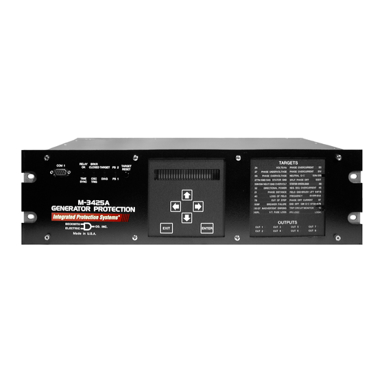
- Page 2 PROTECTION Generator Protection M-3425A Integrated Protection System ® for Generators of All Sizes Unit shown with optional M-3925A Target Module and M-3931 HMI (Human-Machine Interface) Module. • Exceeds IEEE C37.102 and Standard 242 requirements for generator protection • Protects generators of any prime mover, grounding and connection type •...
- Page 3 M-3425A Generator Protection Relay Protective Functions Optional Protective Functions • Sync Check with Phase Angle, ΔV and ΔF Base Package with dead line/dead bus options (25) • Overexcitation (V/Hz) (24) • Field Ground (64F) and Brush Lift Off (64B) • Phase Undervoltage (27) (Includes M-3921 Field Ground Coupler) •...
- Page 4 M-3425A Generator Protection Relay PROTECTIVE FUNCTIONS Device Setpoint Number Function Ranges Increment Accuracy † Phase Distance (three-zone mho characteristic) 0.1 to 100.0 Ω 0.1 Ω 0.1 Ω or 5% Circle Diameter #1,#2,#3 (0.5 to 500.0 Ω) ( 0.5 Ω or 5%) –100.0 to 100.0 Ω...
- Page 5 M-3425A Generator Protection Relay PROTECTIVE FUNCTIONS ( cont .) Device Setpoint Number Function Ranges Increment Accuracy † Third-Harmonic Undervoltage, Neutral Pickup #1, #2 0.10 to 14.00 V 0.01 V 0.1 V or Positive Sequence Voltage Block 5 to 180 V 0.5 V or...
- Page 6 ( 0.02 A or Time Delay 1 to 8160 Cycles 1 Cycle 1 Cycle or 50BF can be initiated from designated M-3425A output contacts or programmable control/status inputs. Definite Time Overcurrent Pickup Phase A #1, #2 0.20 A to 240.00 A 0.01 A 0.1 A or...
- Page 7 M-3425A Generator Protection Relay PROTECTIVE FUNCTIONS ( cont .) Device Setpoint Number Function Ranges Increment Accuracy † Instantaneous Neutral Overcurrent Pickup 0.1 to 240.0 A 0.1 A 0.1 A or (0.1 to 48.0 A) ( 0.02 A or Time Delay...
- Page 8 M-3425A Generator Protection Relay PROTECTIVE FUNCTIONS ( cont .) Device Setpoint Number Function Ranges Increment Accuracy † Phase Overvoltage Pickup #1, #2, #3 5 to 180 V 0.5 V or 0.5% 0.8 V or 0.75%* Time Delay #1, #2, #3...
- Page 9 M-3425A Generator Protection Relay PROTECTIVE FUNCTIONS ( cont .) Device Setpoint Number Function Ranges Increment Accuracy † Residual Directional Overcurrent Definite Time* Pickup 0.5 to 240.0 A 0.1 A 0.1 A or (0.1 to 48.0 A) ( 0.02 A or...
- Page 10 M-3425A Generator Protection Relay PROTECTIVE FUNCTIONS ( cont .) Device Setpoint Number Function Ranges Increment Accuracy † Frequency Accumulation Bands #1, #2, #3, #4, #5, #6 High Band #1 50.00 to 67.00 Hz 0.01 Hz 0.02 Hz 40.00 to 57.00 Hz* Low Band #1–#6...
- Page 11 M-3425A Generator Protection Relay PROTECTIVE FUNCTIONS ( cont .) Device Setpoint Number Function Ranges Increment Accuracy † IPSlogic IPSlogic uses element pickups, element trip commands, control/status input state changes, output contact close signals to develop 6 programmable logic schemes. Time Delay #1–#6...
- Page 12 M-3425A Generator Protection Relay OPTIONAL PROTECTIVE FUNCTIONS Device Setpoint Number Function Ranges Increment Accuracy † Sync Check Dead Check Dead Voltage Limit 0 to 60 V 0.5 V or ±0.5% Dead Time Delay 1 to 8160 Cycles 1 Cycle –1 to +3 Cycles or 1%...
- Page 13 M-3425A Generator Protection Relay Description The M-3425A Generator Protection Relay is suitable for all generator ratings and prime movers. Typical connection diagrams are illustrated in Figure 4, M-3425A One-Line Functional Diagram (configured for phase differential), and Figure 5, One-Line Functional Diagram (configured for split-phase differential).
- Page 14 M-3425A Generator Protection Relay Sequence of Events Log The Sequence of Events Log records relay element status, I/O status, measured values and calculated values time stamped with 1 ms resolution at user-defined events. The Sequence of Events Log includes 512 of the most recently recorded relay events.
- Page 15 IEC 61850 protocol. IRIG-B The M-3425A Generator Protection Relay can accept either modulated or demodulated IRIG-B time clock synchronization signal. The IRIG-B time synchronization information is used to correct the hour, minutes, seconds, and milliseconds information.
- Page 16 M-3425A Generator Protection Relay Temperature Controller Monitoring Any Temperature Controller equipped with a contact output may be connected to the M-3425A and controlled by the relay's programmable IPSlogic function. Figure 1 is an example of a typical Temperature Controller Monitoring application. The Omron E5C2 Temperature Controller is a DIN rail mounted RTD interface to the M-3425A Generator Protection relay.
- Page 17 M-3425A Generator Protection Relay Electrical Environment Electrostatic Discharge Test EN 60255-22-2 Class 4 (8 kV)—point contact discharge EN 60255-22-2 Class 4 (15kV)–air discharge Fast Transient Disturbance Test EN 60255-22-4 Class A (4 kV, 2.5 kHz) Surge Withstand Capability ANSI/IEEE 2,500 V pk-pk oscillatory applied to each independent circuit to earth C37.90.1-...
- Page 18 Patent & Warranty The M-3425A Generator Protection Relay is covered by U.S. Patents 5,592,393 and 5,224,011. The M-3425A Generator Protection Relay is covered by a five year warranty from date of shipment. Specification subject to change without notice. External Connections M-3425A external connection points are illustrated in Figures 2 and 3.
- Page 19 M-3425A Generator Protection Relay –18–...
- Page 20 M-3425A Generator Protection Relay –19–...
- Page 21 When 67N function with I (Residual) operating current is enabled, 87GD is not available, and vice versa. When VT source is used as a turn-to-turn fault protection device (See M-3425A Instruction Book, Chapter 2, Application, for additional 59X applications.) The current input I can be connected either from neutral current or residual current.
- Page 22 The 50BFN, 50N, 51N, 59D, 67N (with I or V ) and 87GD functions are unavailable when the 64S function has been purchased. See the M-3425A Instruction Book for connection details. Figure 5 One-Line Functional Diagram (configured for split-phase diffential) –21–...
- Page 23 M-3425A Generator Protection Relay 17.48 [44.4] ACTUAL 5.21 [13.23] ACTUAL Rear View 10.20 [25.91] 19.00 [48.26] 19.00 [48.26] 0.33 18.34 [46.58] [0.84] 0.40 [1.02] x 0.27 [0.68] SLOT (4x) 2.35 [5.96] 1.35 [3.42] Standard 19" Horizontal Mount Chassis n NOTE: Dimensions in brackets are in centimeters.
- Page 24 M-3425A Generator Protection Relay PANEL CUTOUT 17.50± [44.5 +.30 -.00] 9.97 [25.32] 19.00 [48.26] .25 X .45 SLOT [.64 X 1.14] 4 PLACES OUTPUTS TARGET RELAY BRKR 4.00 COM 1 TARGET CLOSED TARGET RESET [10.16] TIME OSC. DIAG 6.96 SYNC TRIG [17.68]...
- Page 25 ■ NOTES: When mounted vertically, the target module will be located at the top and all front-panel text will be horizontally aligned. Consult Beckwith Electric Co. for details. Expanded I/O not avilable on vertical mount chassis model. Figure 8 Vertical Mounting Dimensions (Without Expanded I/O)
- Page 26 \U+2205.28 (4X) RECOMMENDED CUTOUT STANDARD 3 UNIT PANEL M-3425A 18.34 [46.6] 17.68 [.84] [44.91] 1.48 [3.76] 7.03 [17.86] 4.00 [10.16] \U+2205.28 (4X) RECOMMENDED CUTOUT 4 UNIT PANEL M-3425A (EXTENDED I/O) TOLERANCE: .XX±.015 Figure 9 M-3425A Panel Mount Cutout Dimensions –25–...
- Page 27 M-3425A Generator Protection Relay M-3921 Field Ground Coupler PROTECTION RELAY M-3425A PROCESSOR Excitation System Field Ground Brushes Detection Squarewave Gen. Generator Rotor COUPLING Signal NETWORK Measurement (M-3921) and Processing Shaft Ground Brush Ground/Machine Frame Figure 10 Field Ground Protection Block Diagram...
- Page 28 1989 5,000 V pk Fast Transient applied to each independent circuit to earth 5,000 V pk Fast Transient applied between each independent circuit ■ NOTE: See also M-3425A Surge Withstand Capability test standards, ANSI/IEEE C37.90.2-2002. Radiated Susceptibility ANSI/IEEE 25-1000 Mhz @ 20 V/m C37.90.2...
- Page 29 M-3425A Generator Protection Relay 7.87 [19.99] 2.96 REF [7.52] M-3921 3.54 [9.0] Field Ground Coupler 4.72 [11.99] BECKWIT H CO. INC. EL ECT RIC Made in U.S.A. 9.06 [23.01] 7.40 .18 DIA [0.46] 4 X [18.79] .18 DIA [0.46] 4 HOLES 3.54 [9.0]...
- Page 30 M-3425A relay through a suitable voltage divider, that limits the M-3425A to O O O O O 200 V ac (the voltage generator may be bypassed if the expected 50/60 Hz voltage during a phase-to-ground fault of the generator is O O O O O 200 V.) The 20Hz current is also connected to the I input of the M-3425A, through the 20Hz current transformer.
- Page 31 M-3425A Generator Protection Relay 20 Hz Signal Generator Function Specifications Auxillary Voltage Rated auxiliary voltage U 3x (100/110 V ac), 50/60 Hz 1x (110 to 230 V ac), 50/60 Hz Permissible variations ac 80 to 130 V ac 80 to 265 V ac...
- Page 32 M-3425A Generator Protection Relay Dimensions in mm ■ NOTE: Detailed Mounting information is contained in the M-3425A Instruction Book Chapter 5, Installation Section 5.6. Figure 13 20Hz Signal Generator Dimensions –31–...
- Page 33 M-3425A Generator Protection Relay Band-pass Filter Specifications Load Capacity of the 20 Hz Band-pass Filter Connections (1B1-1B4) Permissible voltage, continuous 55 V ac Permissible voltage for O O O O O 30 s 550 V ac Frequency of superimposed ac voltage P P P P P 45 Hz Overload capability, continuous 3.25 A ac...
- Page 34 M-3425A Generator Protection Relay ■ NOTE: Detailed Mounting information is contained in the M-3425A Instruction Book Chapter 5, Installation Section 5. Figure 14 Band-pass Filter Dimensions –33–...
- Page 35 M-3425A Generator Protection Relay Figure 15 20 Hz Measuring Current Transformer 400-5 A CT –34–...
- Page 36 M-3425A Generator Protection Relay –35–...
- Page 37 © 2001 Beckwith Electric Co. Printed in U.S.A. (#01-67) (04.25.03) 800-3425A-SP-06 07/08...
- Page 38 WARNING DANGEROUS VOLTAGES, capable of causing death or serious injury, are present on the external terminals and inside the equip- ment. Use extreme caution and follow all safety rules when han- dling, testing or adjusting the equipment. However, these internal voltage levels are no greater than the voltages applied to the exter- nal terminals.
- Page 39 PRODUCT CAUTIONS Before attempting any test, calibration, or maintenance procedure, personnel must be completely familiar with the particular circuitry of this unit, and have an adequate understanding of field effect devices. If a component is found to be defective, always follow replacement procedures carefully to that assure safety features are maintained.
- Page 40 NOTE The following features, described in this Instruction Book, are only available for firmware version D-0150-V01.00.34 and later: 59N 20 Hz Injection Mode (Page 2-58) IEEE curves for 51N, 51V, and 67N functions (Appendix D) Sequence of Events Recorder (Page 4-18) Dropout/Reset Time Delay added to IPSlogic (Page 2-91) Response Time Delay for Communications (Page 4-3) 25 Function (does not produce a target) (Page 2-21)
- Page 41 This Page Left Intentionally Blank...
- Page 42 M-3425A Generator Protection Instruction Book Chapters - Part 1 of 2 Page Chapter 1 Introduction Instruction Book Contents ..............1–1 M-3425A Generator Protection Relay ..........1–2 Accessories ..................1–4 Chapter 2 Application Configuration ..................2–2 Profiles ....................2–3 Functions .................... 2–3 Special Considerations ................
- Page 43 M-3425A Instruction Book Chapters - Part 1 of 2 (cont'd) Page Chapter 2 Application (cont'd) 67N Residual Directional Overcurrent ..........2–67 78 Out of Step .................. 2–70 81 Frequency ..................2–73 81A Frequency Accumulators ............2–75 81R Rate of Change of Frequency ............2–77 87 Phase Differential ................2–78...
- Page 44 Serial Ports (RS-232) ................. 4–1 Serial Port (RS-485) ................4–1 Optional Ethernet Port ................. 4–1 Direct Connection ................4–2 Setting up the M-3425A Generator Protection Relay for Communication ..............4–3 Serial Communication Settings ............4–3 Ethernet Communication Settings ............4–3 DHCP Protocol ..................
- Page 45 M-3425A Instruction Book Figures - Part 1 of 2 Page Chapter 1 M-3925A Target Module ..............1–4 M-3931 Human-Machine Interface (HMI) Module ......1–4 Chapter 2 Setup System Dialog Box ..............2–6 Selection Screen for Expanded Input ..........2–7 Pulse Relay Expanded Output Screen ..........2–7 Latch Relay Expanded Output Screen ..........
- Page 46 Table of Contents Figures - Part 1 of 2 Page Chapter 2 (cont'd) 2-26 Tripping on Over Reactive Power with Element #3 (Over Power, Positive Pickup and Directional Power Sensing Set to Reactive) ................2–32 2-27 Directional Power, 3-Phase (32) Setpoint Ranges ......2–32 2-28 Loss of Field (40) Protective Approach 1 ........
- Page 47 Selection Screen for Initiating Function Pickup ........2–87 2-79 Dropout Delay Timer Logic Diagram ...........2–88 2-80 Reset Delay Timer Logic Diagram ............2–88 Chapter 3 M-3425A Front Panel ................. 3–3 Screen Message Menu Flow ............. 3–3 Main Menu Flow ................. 3–4...
- Page 48 Table of Contents Figures - Part 1 of 2 (cont'd) Page Chapter 4 Multiple System Addressing Using Communications Line Splitter ............4–2 ® IPScom Menu Selections ..............4–6 IPScom Program Icon ................ 4–8 New Device Profile Dialog Box ............4–9 Communication Dialog Box ..............
- Page 49 4-47 Setup Dialog Box ................4–33 Tables - Part 1 of 2 Page Chapter 1 M-3425A Device Functions ..............1–3 Chapter 2 Input Activated Profile ............... 2–3 Impedance Calculation ..............2–17 Voltage Control Time Settings ............2–34 Delta/Wye Transformer Voltage-Current Pairs ........ 2–51 Typical Frequency Settings .............
- Page 50 Table of Contents Chapters - Part 2 of 2 Page Chapter 5 Installation General Information ................5–1 Mechanical/Physical Dimensions ............5–2 External Connections ............... 5–10 Commissioning Checkout ..............5–16 Circuit Board Switches and Jumpers ..........5–21 Low Frequency Signal Injection Equipment ........5–25 Chapter 6 Testing Equipment/Test Setup ................
- Page 51 M-3425A Instruction Book Chapters - Part 2 of 2 (cont'd) Page Chapter 6 Testing (cont'd) 87 Phase Differential ................6–59 87GD Ground Differential ..............6–61 BM Breaker Monitoring ...............6–63 Trip Circuit Monitoring ................. 6–65 IPSlogic™ ..................6–66 Diagnostic Test Procedures ...............6–67 Overview .....................6–67 Entering Relay Diagnostic Mode ............
- Page 52 Table of Contents Figures - Part 2 of 2 Page Chapter 5 M-3425A Mounting Dimensions – Horizontal Chassis ..... 5–2 M-3425A Mounting Dimensions – Horizontal Chassis (Expanded I/O) ..............5–3 M-3425A Panel Mount Cutout Dimensions .......... 5–4 M-3425A Mounting Dimensions – Vertical Chassis ......5–5 (H2) Mounting Dimensions ..............
- Page 53 M-3425A Instruction Book Figures (cont'd) Page Chapter 6 (cont'd) 6-10 M-3931 Human/Machine Interface (HMI) Module ........6–71 6-11 COM1/COM2 Loopback Plug ..............6–72 6-12 RS-485 2-Wire Testing ................6–74 6-13 Current Input Configuration ..............6–79 6-14 Voltage Input Configuration ..............6–79 6-15 Voltage Input Configuration ..............6–79 6-16 Voltage Input Configuration ..............6–80...
- Page 54 Communication Port Signals ............. B–2 Appendix C Self-Test Error Codes ................ C–1 ® IPScom Error Messages ..............C–2 Appendix D D-1A M-3425A Inverse Time Overcurrent Relay Characteristic Curves ... D–6 ©1998 Beckwith Electric Co. 800-3425A-IB-04MC2 07/08 Printed in U.S.A. (9.21.01) xiii...
- Page 55 M-3425A Instruction Book This Page Left Intentionally Blank...
- Page 56 The following is a quick review of the and station DC wiring schematics. contents in the chapters of this manual. If during the commissioning of the M-3425A Generator The person or group responsible for the installation Protection Relay, additional tests are desired, Chapter of the relay will find herein all mechanical information 6, Testing, may be consulted.
- Page 57 [48.26] 19.00 [48.26] 0.33 18.34 [46.58] [0.84] 0.40 [1.02] x 0.27 [0.68] SLOT (4x) 2.35 [5.96] 1.35 [3.42] Standard 19" Horizontal Mount Chassis n NOTE: Dimensions in brackets are in centimeters. Figure 5-1 M-3425A Mounting Dimensions – Horizontal Chassis 5–2...
- Page 58 O INC OUTPUTS Made in U.S.A. ENTER EXIT 1.48 OUT 1 OUT 3 OUT 5 OUT 7 OUT 2 OUT 4 OUT 6 OUT 8 3.76 18.34 0.33 [46.58] [0.84] Figure 5-2 M-3425A Mounting Dimensions – Horizontal Chassis (Expanded I/O) 5–3...
- Page 59 \U+2205.28 (4X) RECOMMENDED CUTOUT STANDARD 3 UNIT PANEL M-3425A 18.34 [46.6] 17.68 [.84] [44.91] 1.48 [3.76] 7.03 [17.86] 4.00 [10.16] \U+2205.28 (4X) RECOMMENDED CUTOUT 4 UNIT PANEL M-3425A (EXTENDED I/O) TOLERANCE: .XX±.015 Figure 5-3 M-3425A Panel Mount Cutout Dimensions 5–4...
- Page 60 NOTE: Dimensions in brackets NOT USED AS STANDARD RACK MOUNT are in centimeters. AND IS PANEL CUT OUT MOUNTED Optional Vertical Mount Chassis Figure 5-4 M-3425A Mounting Dimensions – Vertical Chassis ■ NOTE: Expanded I/O not available in Vertical Mount Chassis 5–5...
- Page 61 M-3425A Instruction Book 1.91 2.25 [0.99] [4.85] [5.71] .261 [0.66] Diameter 4 Holes 8.72 [22.15] Recommended Panel Cutout Dimensions 18.21 [46.25] 2.80 2.80 [7.12] [7.12] 19.00 [48.26] 8.72 [22.15] Max. Depth of Unit: 10.50 [26.67] 6.19 [15.72] n NOTE: Dimensions in brackets are in centimeters.
- Page 62 Installation – 5 6.13 [15.57] 5.56 1.04 [14.12] [2.64] .261 [0.66] Diameter 6 Holes 8.72 [22.15] Recommended Panel Cutout Dimensions 18.50 [46.99] 2.80 2.80 [7.12] [7.12] 20.78 [52.78] 15.56 [39.52] 8.72 [22.15] 7.78 [19.76] Max. Depth of Unit: 10.50 [26.67] 2.60 [6.60] 1.14...
- Page 63 M-3425A Instruction Book Ø.281 [Ø0.71] 10 HOLES 9.70 [24.64] Recommended Panel Cutout 19.89 [50.52] Dimensions 20.78 3.48 3.48 [52.78] [8.84] [8.84] 17.72 [45.00] 9.94 9.70 [25.24] [24.64] 2.15 [5.47] [1.13] [1.04] 1.13 [2.87] 6.69 [16.99] 7.81 [19.84] 8.63 [21.92] ■ NOTE: Dimensions in brackets are in centimeters.
- Page 64 Installation – 5 ∅ ∅ 0.71] 10 HOLES 9.70 [24.64] 20.78 [52.78] 19.89 [50.52] 3.53 3.53 [8.97] [8.97] 17.72 [45.00] 9.94 9.70 [25.24] [24.64] 2.15 [5.47] [1.13] [1.04] 1.13 [2.87] 6.69 [16.99] 7.81 [19.84] 8.63 [21.92] FRONT VIEW (H5) Figure 5-8 (H5) Mounting Dimensions 5–9...
- Page 65 Grounding Requirements inputs are internally wetted. Application of external voltage on these inputs may result in The M-3425A is designed to be mounted in an damage to the units. adequately grounded metal panel, using grounding 8 WARNING: Do not open live CT circuits. Live techniques (metal-to-metal mounting) and hardware that assures a low impedance ground.
- Page 66 Installation – 5 5–11...
- Page 67 Application of external voltage on these inputs may result in damage to the units. NOTE : M-3425A current terminal polarity marks ( . ) indicate "entering" current direction when M-3425A primary current is "from" the generator to the Three VT Wye-Wye system.
- Page 68 Installation – 5 M-3425A Used when Generator Side VTs are connected Line-Ground. Used for Sync Ch M-3425A Used when Generator Side are connected Line-Lin M-3425A M-3425A Three VT Wye-Wye Connection M-3425A Two VT Open-Delta Connection Generator Figure 5-13 Function 25 Sync Check Three-Line Connection Diagram...
- Page 69 M-3425A Instruction Book M-3425A M-3425A used for turn-to-turn fault protection (59X) Generator Line to Neutral Voltage Rated Cable M-3425A M-3425A Low Impedance Grounding High Impedance Grounding Figure 5-14 Function 59X Turn to Turn Fault Protection Three-Line Connection Diagram 5–14...
- Page 70 Installation – 5 Bus Section M-3425A input can be connected Residual CT either at Neutral or as Residual. M-3425A Connection M-3425A Bus Ground M-3425A 67N, 59D Connection can be used for both 67N and Generator 59D if connected in this manner.
- Page 71 M-3425A Instruction Book Press ENTER to display Third Harmonic Commissioning Checkout Differential Ratio: 3RD HARMONIC DIFF RATIO During field commissioning, check the following to __________ ensure that the CT and VT connections are correct. Press ENTER once more to display the Press ENTER.
- Page 72 Installation – 5 Press ENTER until the unit displays: Press ENTER for the unit to display: 3RD HARMONIC NTRL VOLT NEUTRAL CURRENT _____ Volts ______ Amps Press ENTER until the unit displays: Press ENTER for the unit to display: FIELD GND MEAS. CIRCUIT GND DIFFERENTIAL CURRENT _______ ______ Amps...
- Page 73 M-3425A Instruction Book Press EXIT, then the Right arrow to Press ENTER to display: display: POWER FACTOR FREQUENCY STATUS __ Lag/Lead volt curr FREQ v/hz Press EXIT and then right arrow to display: Press ENTER to display: IMPEDANCE STATUS FREQUENCY...
- Page 74 Installation – 5 Press ENTER to display: Press ENTER to display: DELTA FREQUENCY FL I6 I5 I4 I3 I2 I1 _____ Hz HI Press ENTER again to view outputs: Press EXIT, then right arrow until unit O8 O7 O6 O5 O4 O3 O2 O1 displays: BREAKER MON ACC.
- Page 75 M-3425A Instruction Book Press EXIT, then right arrow until unit Press ENTER to display: displays: COMM ERROR CODE (LAST) COUNTERS __________ temp COUNT powerup Press ENTER to display: Press ENTER to display: COMM PACKET COUNTER __________ OUTPUT COUNTER 1 __________...
- Page 76 Remove the screws that retain the front Jumpers cover. Remove the "J" connectors from the See Figure 5-16, M-3425A Circuit Board for Jumper corresponding plugs, P4, 5, 6, 7, 9 and and Switch locations. Loosen the two circuit board retention...
- Page 77 M-3425A Instruction Book Switches should not be changed while unit is energized. i n I l a i t e z i * t l i t u o l e i n I l a i t e z i...
- Page 78 Installation – 5 5–23...
- Page 79 M-3425A Instruction Book RV14 5–24...
- Page 80 20 Hz Band Pass A(L1) Filter B(L2) C(L3) External Block Device 400A Neutral Operative Wiring Grounding Shielded Transformer High 400/5 A Voltage 20 Hz CT M-3425A Max. 200 V Voltage Figure 5-18 Low Frequency Signal Injection Equipment Typical Connections 5–25...
- Page 81 M-3425A Instruction Book Figure 5-19 20 Hz Frequency Generator Housing Panel Surface Mount 5–26...
- Page 82 Installation – 5 Figure 5-20 20 Hz Frequency Generator Housing Panel Flush Mount 5–27...
- Page 83 M-3425A Instruction Book Figure 5-21 20 Hz Band Pass Filter Housing Panel Surface Mount 5–28...
- Page 84 Installation – 5 Figure 5-22 20 Hz Band Pass Filter Housing Panel Flush Mount 5–29...
- Page 85 M-3425A Instruction Book Figure 5-23 20 Hz Measuring Current Transformer 400-5 A CT 5–30...
-
Page 86: Table Of Contents
Testing – 6 Testing Equipment/Test Setup ............... 6–2 Functional Test Procedures ............6–6 Power On Self Tests ..............6–7 21 Phase Distance ..............6–8 24 Volts per Hertz ..............6–9 25D/25S Sync Check .............. 6–12 27 Phase Undervoltage ............6–16 27TN Third-Harmonic Undervoltage, Neutral ...... -
Page 87: Equipment/Test Setup
M-3425A Instruction Book Equipment/Test Setup No calibration is necessary, as the M-3425A For relays with the 64F/B option: Generator Protection Relay is calibrated and fully a. Resistor decade box capable of 500 tested at the factory. If calibration is necessary... - Page 88 Testing – 6 ■ NOTE: The phase angles shown here use leading angles as positive and lagging angles as nega- tive. Some manufacturers of test equipment have used lagging angles as positive, in which case =120 V a120° and V =120 V a240°.
- Page 89 M-3425A Instruction Book Polarity ∠ 0° Current Input 1 ∠ Current Input 2 –120° ∠ 120° Current Input 3 Figure 6-3 Current Inputs: Configuration C1 Polarity ∠ 0° Current Input 1 ∠ Current Input 2 –120° ∠ 120° Current Input 3 Figure 6-4 Current Inputs: Configuration C2 6–4...
- Page 90 Testing – 6 Polarity 55 • 0° aø Current Input 1 • bø • cø Polarity 47 • AØ 0° Current Input 2 • BØ • CØ Figure 6-5 Current Configuration C3 20 Hz Voltage Source (Variable) 20 Hz Current Source (Variable) Figure 6-6 64S Test Configuration 6–5...
-
Page 91: Functional Test Procedures
M-3425A Instruction Book The tests are described in this section in ascending Functional Test Procedures function number order as used in Chapter 2, Application. This section details test quantities, inputs and ■ NOTE: User should disable all functions not procedures for testing each relay function. The currently being tested before beginning purpose is to confirm the functions’... -
Page 92: Power On Selftests
The POWER and RELAY OK LEDs will remain illuminated, all other LEDs will extinguish. The unit will display the following: POWER ON SELFTESTS PASS The unit will display the model number: BECKWITH ELECTRIC CO. M-3425A Expanded The unit will display the firmware version. BECKWITH ELECTRIC D-0150xx.xx.xx The unit will display the serial number. -
Page 93: Phase Distance
M-3425A Instruction Book 21 Phase Distance (#1, #2 or #3) VOLTAGE INPUTS: Configuration V1 CURRENT INPUTS: Configuration C1 TEST SETTINGS: Diameter Ohms (0.1 to 100) 1 Amp CT Rating (0.5 to 500.0) Offset Ohms (–100 to 100) 1 Amp CT Rating (–500.0 to 500.0) - Page 94 Testing – 6 24 Volts/Hz Definite Time (#1 or #2) VOLTAGE INPUTS: Configuration V1 CURRENT INPUTS: None TEST SETTINGS: Definite Time Pickup (100 to 200) Time Delay Cycles (30 to 8160) Programmed Outputs Output (1 to 8) Expanded I/O (9 to 23) ■...
- Page 95 M-3425A Instruction Book 24 Volts/Hz Inverse Time VOLTAGE INPUTS: Configuration V1 CURRENT INPUTS: None TEST SETTINGS: Inverse Time Pickup (100 to 200) Inverse Time Curve (1 to 4) Time Dial (Curve 1) (1 to 100) Time Dial (Curves 2-4) (0.0 to 9.0)
- Page 96 Testing – 6 Press and hold the TARGET RESET pushbutton. Reduce the applied voltage and start timing when the voltage drops below the pickup value, stop timing when the TARGET LED extinguishes. The time should be the reset time within ±1 cycle or ±1%, whichever is greater.
- Page 97 M-3425A Instruction Book 25D Dead Check VOLTAGE INPUTS: Configuration V1 CURRENT INPUTS: None TEST SETTINGS: Dead V1 See Below Dead V See Below Dead V1 & V See Below Dead Input Enable Input (1 to 6) Expanded I/O (7 to 14)
- Page 98 Testing – 6 Dead V Hot V1 Test: Enable Dead V Hot V1 and disable Dead V1 Hot V (if enabled) utilizing either the HMI or IPScom Communications Software. Set V1 to the Nominal Voltage. The Nominal Voltage value previously input to the relay is described in Section 2.1 and should be recorded on Figure A-3, Functional Configuration Record Form.
- Page 99 M-3425A Instruction Book 25S Sync Check VOLTAGE INPUTS: Configuration V1 CURRENT INPUTS: None TEST SETTINGS: Phase Angle Window Degrees (0 to 90) Voltage Limits Upper Limit Volts (60 to 140) Lower Limit Volts (40 to 120) Sync Check Time Delay...
- Page 100 Testing – 6 Upper Voltage Limit Test: Apply a voltage 5 V greater than UL to V1. Ensure V voltage is less than UL but greater than LL. Slowly decrease the voltage applied to V1 until Output Z LED illuminates, or the pickup indicator illuminates on the IPScom Function Status screen.
- Page 101 M-3425A Instruction Book 27 Phase Undervoltage, 3 Phase (#1, #2, #3) VOLTAGE INPUTS: Configuration V1 CURRENT INPUTS: None TEST SETTINGS: Pickup Volts (5 to 180) Time Delay Cycles (1 to 8160) Programmed Outputs (1 to 8) Expanded I/O (9 to 23) ■...
- Page 102 Testing – 6 27TN Third-Harmonic Undervoltage, Neutral (#1 or #2) VOLTAGE INPUTS: Configuration V2 CURRENT INPUTS: See Below TEST SETTINGS: Pickup Volts (0.10 to 14.0) Positive Sequence Volt Block Volts (5 to 180) Forward Power Block (0.01 to 1.00) Reverse Power Block (–1.00 to –0.01) Lead VAR Block –VAR...
- Page 103 M-3425A Instruction Book Positive Sequence Voltage Block Test: Decrease the neutral voltage input to less than P volts. Apply a three phase voltage input greater than PSV volts. The 27TN/59D 100% STATOR GND LED will illuminate, then the OUTPUT LED will illuminate when the delay setting has timed out.
- Page 104 Testing – 6 ■ ■ ■ ■ ■ NOTE: The POWER Reactive var value can be obtained utilizing either the HMI (Status/ ® Power Status) or IPScom Communications Software (Relay/Monitor/Secondary Status). Adjust three phase voltage and current inputs to obtain a Power Reactive var value greater than –VAR.
- Page 105 M-3425A Instruction Book Forward Power Block (Band) Test: Apply a three phase nominal voltage input. The Nominal Voltage value previously input to the relay is described in Section 2.1 and should be recorded on Figure A-3, Functional Configuration Record Form.
-
Page 106: Directional Power, 3-Phase
Testing – 6 32 Directional Power, 3 Phase (#1, #2, #3) VOLTAGE INPUTS: Configuration V1 CURRENT INPUTS: Configuration C1 TEST SETTINGS: Pickup (–3.000 to +3.000) Time Delay Cycles (1 to 8160) Programmed Outputs (1 to 8) Expanded I/O (9 to 23) VT Configuration Line-Ground Power Sensing... - Page 107 M-3425A Instruction Book Pickup Test , Negative/Reverse Over Power Flow: Set the phase currents at 180 degrees from the respective phase voltages. Press and hold the TARGET RESET pushbutton, then slowly increase the three phase currents until the 32 DIRECTIONAL POWER LED illuminates, or the pickup indicator illuminates on the IPScom ®...
- Page 108 Testing – 6 Pickup Test , Reactive Under Power (Element #3 Only): Set the Three phase voltages, current magnitudes and phase angles to greater than the Reactive p.u. pickup level. Press and hold the TARGET RESET pushbutton, then slowly swing current angles until the 32 ®...
-
Page 109: Loss Of Field
M-3425A Instruction Book 40 Loss of Field (#1 or #2, VC #1 or #2) VOLTAGE INPUTS: Configuration V1 CURRENT INPUTS: Configuration C1 TEST SETTINGS: Circle Diameter Ohms (0.1 to 100) 1 Amp CT Rating (0.5 to 500) Offset Ohms (–50 to 50) 1 Amp CT Rating (–250 to 250) - Page 110 Testing – 6 If the offset setting is negative, continue to increase the three-phase currents until the 40 LOSS ® OF FIELD LED light extinguishes, or the pickup indicator extinguishes on the IPScom Function Status screen. The level will be equal to “IO” calculated in Step 6 with the resulting offset impedance within ±0.1 ohms or ±5%.
- Page 111 M-3425A Instruction Book 46 Negative Sequence Overcurrent Definite Time VOLTAGE INPUTS: None CURRENT INPUTS: Configuration C1 (MODIFIED) TEST SETTINGS: Pickup Def Time (3 to 100) Time Delay Cycles (1 to 8160) Programmed Outputs (1 to 8) Expanded I/O (9 to 23) ■...
- Page 112 Testing – 6 46 Negative Sequence Overcurrent Inverse Time VOLTAGE INPUTS: None CURRENT INPUTS: Configuration C1 (MODIFIED) TEST SETTINGS: Pickup Inv Time (3 to 100) Time Dial Setting (1 to 95) Maximum Trip Time Cycles (600 to 65,500) Reset Time Seconds (1 to 600) Programmed Outputs...
-
Page 113: Stator Overload
M-3425A Instruction Book 49 Stator Overload Protection (#1, #2) VOLTAGE INPUTS: None CURRENT INPUTS: Configuration C1 τ TEST SETTINGS: Time Constant Minutes (1.0 to 999.9) Max Overload Current Amps (1 to 10) 1 Amp CT Rating (.2 to 2) Programmed Outputs... - Page 114 Testing – 6 Time Test (Cold Start) : Connect a timer to output contacts (Z) so that the timer stops timing when the contacts (Z) close. ■ ■ ■ ■ ■ NOTE: The 49 Stator Overload 49 #1 and 49 #2 current values can be obtained utilizing either the HMI ®...
-
Page 115: Instantaneous Phase Overcurrent
M-3425A Instruction Book 50 Instantaneous Phase Overcurrent (#1, #2) VOLTAGE INPUTS: None CURRENT INPUTS: Configuration C1 TEST SETTINGS: Pickup Amps (0.1 to 240.0) 1 Amp CT Rating (0.1 to 48.0) Delay Cycles (1 to 8160) Programmed Outputs (1 to 8) -
Page 116: 50Bf/50Bf-N Breaker Failure
Testing – 6 50BF/50BF-N Breaker Failure VOLTAGE INPUTS: None CURRENT INPUTS: Configuration C3 TEST SETTINGS: 50BF-Ph Pickup Amps (0.10 to 10.00) 1 Amp CT Rating (0.02 to 2.00) 50BF-N Pickup Amps (0.10 to 10.00) 1 Amp CT Rating (.02 to 2.00) Time Delay Cycles (1 to 8160) - Page 117 M-3425A Instruction Book Test Setup for 50BF-N Generator Breaker Failure Operation: Determine the Function 50BF-Ph Generator Breaker Failure settings to be tested. ® Utilizing either the HMI or IPScom Communications Software enter the following settings: a. Enable the 50BF-Neutral Element and the 50BF-Phase Element b.
-
Page 118: 50/27 Inadvertent Energizing
Testing – 6 50/27 Inadvertent Energizing VOLTAGE INPUTS: Configuration V1 CURRENT INPUTS: Configuration C1 TEST SETTINGS: 50 Pickup Amps (0.50 to 15.00) 1 Amp CT Rating (.01 to 3.00) 27 Pickup Volts (5 to 130) Pickup Delay Cycles (1 to 8160) Dropout Delay Cycles (1 to 8160) -
Page 119: 50Dt Definite Time Overcurrent For
M-3425A Instruction Book 50DT Definite Time Overcurrent (for split-phase differential), #1 or #2 VOLTAGE INPUTS: None CURRENT INPUTS: Configuration C2 TEST SETTINGS: Pickup A Phase Amps (0.20 to 240.00) 1 Amp CT Rating (0.04 to 48.00) Pickup B Phase Amps (0.20 to 240.00) -
Page 120: Instantaneous Neutral Overcurrent
Testing – 6 50N Instantaneous Neutral Overcurrent VOLTAGE INPUTS: None CURRENT INPUTS: As described TEST SETTINGS: Pickup Amps (0.1 to 240.0) 1 Amp CT Rating (0.1 to 48.0) Time Delay Cycles (1 to 8160) Programmed Outputs (1 to 8) Expanded I/O (9 to 23) ■... -
Page 121: Inverse Time Neutral Overcurrent
M-3425A Instruction Book 51N Inverse Time Neutral Overcurrent VOLTAGE INPUTS: None CURRENT INPUTS: As described TEST SETTINGS: Pickup Amps (0.25 to 12.00) 1 Amp CT Rating (0.05 to 2.40) BECO Time Curves (definite time/inverse/very inverse/extremely inverse) Time Dial Setting (0.5 to 11.0) -
Page 122: Inverse Time Phase Overcurrent With Voltage Control/Restraint
Testing – 6 51V Inverse Time Phase Overcurrent with Voltage Control/Restraint VOLTAGE INPUTS: Configuration V1 CURRENT INPUTS: Configuration C1 TEST SETTINGS: Pickup Amps (0.50 to 12.00) 1 Amp CT Rating (0.10 to 2.40) BECO Time Curves (definite time/inverse/very inverse/extremely inverse) Time Dial Setting (0.5 to 11.0) IEC Inverse Time Curves:... - Page 123 M-3425A Instruction Book Apply current equal to the chosen test level calculated in Step 6 to Phase A Current Input and start timing. The operating time will be as read from the appropriate Inverse Curve Family and K (Time Dial) setting in Appendix D, Figures D-5 through D-8, or Tables D-1A through D-1B. The accuracy specified is valid for currents above 1.5 times the pickup current.
- Page 124 Testing – 6 59 Phase Overvoltage, 3-Phase (#1, #2, #3) VOLTAGE INPUTS: Configuration V1 CURRENT INPUTS: None TEST SETTINGS: Pickup Volts (5 to 180) Time Delay Cycles (1 to 8160) Input Voltage Select (Phase or Positive Sequence) Programmed Outputs (1 to 8) Expanded I/O (9 to 23) ■...
-
Page 125: Third Harmonic Voltage Differential
M-3425A Instruction Book 59D Third-Harmonic Voltage Differential VOLTAGE INPUTS: As described CURRENT INPUTS: None TEST SETTINGS: Ratio (0.1 to 5.0) Time Delay Cycles (1 to 8160) Line Side Voltage or 3V Calculated) Programmed Outputs (1 to 8) Expanded I/O (9 to 23) Test Setup: Determine the Function 59D Third-Harmonic Voltage Differential settings to be tested. -
Page 126: Overvoltage, Neutral Circuit Or Zero Sequence
Testing – 6 59N Overvoltage, Neutral Circuit or Zero Sequence (#1, #2, #3) VOLTAGE INPUTS: As described CURRENT INPUTS: None TEST SETTINGS: Pickup Volts (5.0 to 180) Time Delay Cycles (1 to 8160) Programmed Outputs (1 to 8) Expanded I/O (9 to 23) ■... -
Page 127: Multipurpose Overvoltage
M-3425A Instruction Book 59X Multi-purpose Overvoltage (#1 or #2) VOLTAGE INPUTS: As described CURRENT INPUTS: None TEST SETTINGS: Pickup Volts (5.0 to 180.0) Time Delay Cycles (1 to 8160) Programmed Outputs (1 to 8) Expanded I/O (9 to 23) ■ ■ ■ ■ ■ NOTE: If 59X #1 and 59X #2 have different pickup settings, it would be efficient to disable the one with the lower setting first and test the higher setting operation. -
Page 128: 60Fl Vt Fuse Loss Detection
Testing – 6 60FL VT Fuse Loss Detection VOLTAGE INPUTS: Configuration V1 CURRENT INPUTS: Configuration C1 TEST SETTINGS: Time Delay Cycles (1 to 8160) Programmed Outputs (1 to 8) Expanded I/O (9 to 23) ■ ■ ■ ■ ■ NOTE: It is necessary for “FL” to be designated as an initiating input (see Section 2.3, Setpoints and Time Settings) before this function can be tested. -
Page 129: Field Ground Protection
M-3425A Instruction Book 64F Field Ground Protection (#1 or #2) VOLTAGE INPUTS: None CURRENT INPUTS: None TEST SETTINGS: Pickup kOhms (5 to 100) Time Delay Cycles (1 to 8160) Injection Frequency (0.10 to 1.00) Programmed Outputs (1 to 8) Expanded I/O... - Page 130 2 & 3 must be removed when calibration is complete. Placing the M-3921 in service with this jumper installed will result in serious damage. M-3425A 60 to 100 V dc source - simulates Exciter Supply Voltage PROCESSOR...
-
Page 131: Brush Lift Off Detection
M-3425A Instruction Book 64B Brush Lift-Off Detection VOLTAGE INPUTS: None CURRENT INPUTS: None TEST SETTINGS: Pickup (0 to 5000) Time Delay Cycles (1 to 8160) Injection Frequency (0.10 to 1.00) Programmed Outputs (1 to 8) Expanded I/O (9 to 23) Test Setup: Determine the Function 64F Field Ground Protection settings to be tested. - Page 132 Testing – 6 64S 100% Stator Ground Protection by low frequency injection VOLTAGE INPUTS: Adjustable 20 Hz Voltage Source (0 to 40 V) CURRENT INPUTS: Adjustable 20 Hz Current Source (0 to 40 mA) TEST SETTINGS: Pickup (2 to 40) Time Delay Cycles (1 to 8160)
- Page 133 M-3425A Instruction Book Pickup Test (Undervoltage Inhibit Enabled) : ■ ■ ■ ■ ■ NOTE: This test assumes that the value of X is less than 25 Volts. Enable the 64S Undervoltage Inhibit utilizing either the HMI or IPScom Communications Software.
- Page 134 Testing – 6 67N Residual Directional Overcurrent, Definite Time VOLTAGE INPUTS: See Below CURRENT INPUTS: See Below TEST SETTINGS: Pickup Amps (0.50 to 240.0) 1 Amp (0.1 to 48.0) Directional Element See Below Time Delay Cycles (1 to 8160) Max Sensitivity Angle Degrees (0 to 359) Operating Current...
- Page 135 M-3425A Instruction Book Directional Test : Enable the Directional Element utilizing either the HMI or IPScom Communications Software. Press the TARGET RESET pushbutton to reset targets. Set the voltage of the selected polarization type to the Nominal Voltage (If 3V is selected, use any one of the phase voltages, or all three in zero sequence.) The Nominal Voltage value...
- Page 136 Testing – 6 6 6 6 6 6 7N Residual Directional Overcurrent, Inverse Time VOLTAGE INPUTS: See Below CURRENT INPUTS: See Below TEST SETTINGS: Pickup Amps (0.25 to 12.0) 1 Amp CT Rating (0.05 to 2.40) Directional See Below BECO Inverse Time Curves Definite Time\Inverse\Very Inverse\Extremely Inverse Time Dial (0.5 to 11.0)
- Page 137 M-3425A Instruction Book Directional Test : Enable Directional Element. Press the TARGET RESET pushbutton to reset targets. Apply Nominal Voltage to the input of the selected Polarization Type. If 3V , use any one of the phase voltages, or all three at zero sequence.
-
Page 138: Out Of Step
Testing – 6 78 Out of Step VOLTAGE INPUTS: Configuration V1 CURRENT INPUTS: Configuration C1 TEST SETTINGS: Circle Diameter Ohms (0.1 to 100) 1 Amp CT Rating (0.5 to 500) Offset Ohms (–100 to 100) 1 Amp CT Rating (–500 to 500) Impedance Angle Degrees (0 to 90) - Page 139 M-3425A Instruction Book Pause testing until the delay timer has time to expire, then continue to sweep the current angle to point Z , and verify output Z operates as point Z is crossed, and resets after the seal-in time delay.
-
Page 140: Frequency
Testing – 6 81 Frequency (#1, #2, #3, #4) VOLTAGE INPUTS: Configuration V1 CURRENT INPUTS: None TEST SETTINGS: Pickup (50.00 to 67.00) 50 Hz Relay (40.00 to 57.00) Time Delay Cycles (3 to 65,500) 50 Hz Relay Programmed Outputs (1 to 8) Expanded I/O (9 to 23) ■... -
Page 141: Frequency Accumulator
M-3425A Instruction Book 81A Frequency Accumulator (Band #1, #2, #3, #4, #5, #6) VOLTAGE INPUTS: CURRENT INPUTS: None TEST SETTINGS: High Pickup (#1 only) (50.00 to 67.00) 50 Hz Relay (40.00 to 57.00) Low Pickup (50.00 to 67.00) 50 Hz Relay (40.00 to 57.00) -
Page 142: Rate Of Change Of Frequency
Testing – 6 81R Rate of Change of Frequency (#1, #2) VOLTAGE INPUTS: Configuration V1 CURRENT INPUTS: None TEST SETTINGS: Pickup Hz/Sec (0.10 to 20.00) Time Delay Cycles (3 to 8160) Negative Sequence Voltage Inhibit (0 to 99) Programmed Outputs (1 to 8) Expanded I/O (9 to 23) - Page 143 M-3425A Instruction Book Pickup Test : Calculate the time for the pickup setting, then apply a sweep rate of 25% less than the Pickup (P) to all three phases. Press and hold the TARGET RESET pushbutton, then slowly decrease the sweep time until the FREQUENCY/ROCOF 81/81R LED illuminates, or the function status indicator on the Monitor Function Status screen indicates that the function has picked up.
-
Page 144: Phase Differential
Testing – 6 87 Phase Differential (#1 or #2) VOLTAGE INPUTS: None CURRENT INPUTS: Configuration C3 TEST SETTINGS: Minimum Pickup Amps (0.20 to 3.00) 1 Amp CT Rating (0.04 to 0.60) Percent Slope (1 to 100) Time Delay Cycles (1 to 8160) CT Correction Amps (0.5 to 2.0) - Page 145 M-3425A Instruction Book Slope Test: Define a representative number of testing points to verify the trip curve. For each I (Current Input 1) test point defined in Step 1, calculate the expected operating current I (Current Input 2) as follows: >...
-
Page 146: 87Gd Ground Differential
Testing – 6 87GD Ground Differential VOLTAGE INPUTS: None CURRENT INPUTS: As described TEST SETTINGS: Pickup Amps (0.20 to 10.00) 1 Amp CT Rating (0.04 to 2.00) ▲ ▲ ▲ ▲ ▲ CAUTION: Do NOT set the delay to less than 2 Cycles Time Delay Cycles (1 to 8160) - Page 147 M-3425A Instruction Book Press the TARGET RESET pushbutton to reset targets. Set the phase angle of the Current Input selected in Step 3, to 0 degrees, the Current Inputs are now in phase. Reapply a current of 1.0 Amp to Current Input I (terminals 53 and 52).
-
Page 148: Breaker Monitoring
Testing – 6 BM Breaker Monitoring VOLTAGE INPUTS: None CURRENT INPUTS: As Described TEST SETTINGS: Pickup kAmps (kA (0 to 50,000) Delay Cycles (0.1 to 4095.9) Timing Method T or Preset Accumulators Phase A, B, or C kAmp (kA ) Cycles*(0 to 50,000) Programmed Outputs (1 to 8) Blocking Inputs... - Page 149 M-3425A Instruction Book Utilizing either the HMI (Status/Breaker Monitor Accumulator Status) or IPScom Communications Software (Relay/Monitor/Accumulator Status) to monitor the accumulator value, place a jumper between the designated input or output contact selected as initiate and then remove the jumper.
-
Page 150: Trip Circuit Monitoring
Testing – 6 Trip Circuit Monitoring VOLTAGE INPUTS: As Described CURRENT INPUTS: None TEST SETTINGS: Delay Cycles (1 to 8160) Programmed Outputs (1 to 8) Expanded I/O (9 to 23) Test Setup: Determine the Trip Circuit Monitoring function settings to be tested. Disable all other functions prior to testing. -
Page 151: Ipslogic
M-3425A Instruction Book IPSlogic (#1, #2, #3, #4, #5, #6) VOLTAGE INPUTS: As Needed CURRENT INPUTS: As Needed TEST SETTINGS: Time Delay Cycles (1 to 8160) Programmed Outputs (1 to 8) Expanded I/O (9 to 23) Blocking Inputs (1 to 6) -
Page 152: Diagnostic Test Procedures
Testing – 6 Press the right arrow pushbutton until Diagnostic Test Procedures the following is displayed: SETUP UNIT Overview SETUP exit The diagnostic test procedures perform basic functional relay tests to verify the operation of the front-panel controls, inputs, outputs, and Press ENTER, the following will be communication ports. - Page 153 M-3425A Instruction Book Output Relay Test (Output Relays 1–23 and 25) If the relay is already in the Diagnostic Mode, then go to Step 4. ■ ■ ■ ■ ■ NOTE: This test does not include testing of Power Supply Relay (Output Relay 24).
- Page 154 Testing – 6 If all Diagnostic Testing is complete, Input Test (Control/Status) then exit the diagnostic menu by pressing The INPUT TEST menu enables the user to EXIT, PRESS EXIT EXIT determine the status of the individual control/status DIAGNOSTIC MODE is displayed, then inputs.
- Page 155 M-3425A Instruction Book Ensure that the Diagnostic Menu is When input testing is complete then selected to INPUT (Upper Case). insure all jumpers have been removed and press EXIT to return to the Diagnostic INPUT TEST (RELAY) Menu. output INPUT led target...
- Page 156 FIELD GND/BRUSH LIFT64F/B LOSS OF FIELD FREQUENCY 81/81R/81A OUT OF STEP PHASE DIFF CURRENT 50BF BREAKER FAILURE GND DIFF/DIR O/C 87GD/67N BECKWITH ELECTRIC CO. 50/27INADVERTENT ENRGNG TRIP CIRCUIT MONITOR TC M-3425A IPS LOGIC LOGIC 60FL V.T. FUSE LOSS OUTPUTS OUT 1...
- Page 157 M-3425A Instruction Book Ensure that the Diagnostic Menu is Ensure that the Diagnostic Menu is selected to BUTTON (Upper Case). selected to DISPLAY TEST (Upper Case). BUTTON TEST DISPLAY TEST output input led target output input led target BUTTON disp...
- Page 158 Testing – 6 If the relay is already in the Diagnostic Ensure that the Diagnostic Menu is Mode, then go to Step 2. selected to COM2 LOOPBACK TEST (Upper Case). If the relay is NOT in the Diagnostic COM2 LOOPBACK TEST Mode, then enter the relay diagnostic output input led target mode by performing the steps described...
- Page 159 M-3425A Instruction Book From the rear of the unit, connect a PC Clock ON/OFF to the relay at terminals 3(-) and 4(+) This feature provides the user with the ability to using an RS-485 converter set for 2-wire either start or stop the clock.
- Page 160 Testing – 6 b. If the clock was NOT running the Press ENTER, the following will be following will be displayed: displayed: CLOCK TEST FLASH RELAY OK LED CLOCK START OFF on Select (upper case) either ON (to flash) CLOCK TEST or OFF (to Illuminate) by pressing the 01-Jan-2003 01:01:01 right/left arrow pushbutton once.
- Page 161 Press ENTER, the following will be Auto Calibration displayed: CONNECT REFERENCE INPUTS ■ ■ ■ ■ ■ NOTE: The M-3425A Generator Protection Relay PRESS ENTER TO CALIBRATE has been fully calibrated at the factory. There is no need to recalibrate the unit Connect V =120.0...
-
Page 162: Auto-Calibration
Testing – 6 Third Harmonic Calibration b. Connect V =120.0 V, 180 Hz (150 Hz for 50 Hz units). See Figure If it is desired to calibrate the third 6-16. harmonic only and the relay is already in the Diagnostic Mode, then go to Step 2. Press ENTER, the following will be displayed while the Third Harmonic is If it is desired to calibrate the third... - Page 163 Calibration is necessary for long cable lengths CALIBRATING (greater than 100 feet) to compensate for cabling DONE losses from the M-3425A and the M-3921 Coupler module, and therefore should be accomplished in Press ENTER, the unit will display the system, after all wiring is complete.
- Page 164 Testing – 6 Polarity Current Input Figure 6-13 Current Input Configuration Voltage Input Neutral Voltage Input Neutral Figure 6-14 Voltage Input Configuration Neutral Voltage Input Neutral Figure 6-15 Voltage Input Configuration 6–79...
- Page 165 M-3425A Instruction Book Voltage Input Neutral Figure 6-16 Voltage Input Configuration 6–80...
- Page 166 Figure A-3, Functional Configuration Record Form recording the configuration and setting of the reproduces the Configure Relay menus. For each M-3425A Generator Protection Relay. The forms function or setpoint, refer to the configuration you can be supplied to field service personnel for...
- Page 167 M-3425A Instruction Book ✓ (See page A-1 for information on using this table.) Check each box applicable : D Column = Function Disabled. OUTPUTS Columns =Designated function output(s) fl Column = Function blocked by fuse loss. INPUTS Columns =Designated function blocking input(s) Table A-1 Relay Configuration Table (page 1 of 4) A–2...
- Page 168 Appendix – A FUNCTION 60FL 87GD TCKT ✓ (See page A-1 for information on using this table.) Check each box applicable : D Column = Function Disabled. OUTPUTS Columns =Designated function output(s) fl Column = Function blocked by fuse loss. INPUTS Columns =Designated function blocking input(s) Table A-1 Relay Configuration Table (page 2 of 4) A–3...
- Page 169 M-3425A Instruction Book EXPANDED OUTPUTS EXPANDED INPUTS FUNCTION 27TN 50BF 50DT 50/27 Table A-1 Relay Configuration Table (page 3 of 4) A–4...
- Page 170 Appendix – A Table A-1 Relay Configuration Table - Expanded I/O (page 4 of 4) A–5...
- Page 171 M-3425A Instruction Book KEY TO INPUT DATA RECORD FORMS All heavily bordered screens are either MENU screens which have horizontal choices (made with right - left arrows) or screens displaying a result of a choice previously made. Dashed boxes enclose screens which bound areas that pushbutton ENTER will move in.
- Page 172 Appendix – A COMMUNICATION targets osc_rec COMM COM1 SETUP COM3 SETUP COM1 com2 com3 com-adr com1 com2 COM3 com_adr COM1 BAUD RATE COM3 DEAD SYNC TIME baud_300 baud_600 baud_1200 ________ MS baud_4800 BAUD_9600 COM3 PROTOCOL beco2200 MODBUS COM2 SETUP com1 COM2 com3 com_adr COM3 PARITY NONE odd even COM2 BAUD RATE...
- Page 173 M-3425A Instruction Book COMMUNICATION targets osc_rec COMM ETHERNET ETHERNET PROTOCOL dly accss ETH eth_ip tcp PROT ETHERNET SELECT PROTOCOL disable ENABLE modbus serconv TCP/IP SETTINGS ETHERNET ADDRESS TCP prot accss eth ETH_IP ETHERNET IP ADDRESS DHCP PROTOCOL XX.XX.XX.XX disable ENABLE...
- Page 174 Appendix – A SETUP UNIT SETUP exit SOFTWARE VERSION CLEAR ALARM COUNTER VERS sn access number logo1 logo2 out ALRM SOFTWARE VERSION CLEAR ALARM COUNTER D-XXXXV__.__.__ PRESS ENTER KEY TO CLEAR SERIAL NUMBER DATE & TIME vers SN access number TIME error eth_ver SERIAL NUMBER DATE &...
- Page 175 M-3425A Instruction Book CONFIGURE RELAY CONFIG sys stat CONFIGURE RELAY VOLTAGE_RELAY 59 #1 PHASE OVERVOLTAGE 27 #1 PHASE UNDERVOLTAGE disable ENABLE disable ENABLE 59 #1 BLOCK INPUT 27 #1 BLOCK INPUT fl i6 i5 i4 i3 i2 i1 fl i6 i5 i4 i3 i2 i1...
- Page 176 Appendix – A CONFIGURE RELAY CONFIG sys stat CONFIGURE RELAY VOLTAGE_RELAY 59X #2 OVERVOLTAGE 27TN #1 NEUTRL UNDERVOLT disable ENABLE disable ENABLE 27TN #1 BLOCK INPUT 59X #2 BLOCK INPUT fl i6 i5 i4 i3 i2 i1 fl i6 i5 i4 i3 i2 i1 i11 i10 i9 i8 i7 i11 i10 i9 i8 i7 i14 i13 i12...
- Page 177 M-3425A Instruction Book CONFIGURE RELAY CONFIG sys stat CONFIGURE RELAY VOLTAGE_RELAY 59N #2 NEUTRAL OVERVOLT 59D VOLTAGE DIFF. disable ENABLE disable ENABLE 59N #2 BLOCK INPUT 59D BLOCK INPUT fl i6 i5 i4 i3 i2 i1 fl i6 i5 i4 i3 i2 i1...
- Page 178 Appendix – A CONFIGURE RELAY CONFIG sys stat CONFIGURE RELAY CURRENT_RELAY 50 #2 INST OVERCURRENT 46DT NEG SEQ CURRENT DEF disable enable disable ENABLE 50 #2 BLOCK INPUT 46DT BLOCK INPUT fl i6 i5 i4 i3 i2 i1 fl i6 i5 i4 i3 i2 i1 i11 i10 i9 i8 i7 i11 i10 i9 i8 i7 i14 i13 i12...
- Page 179 M-3425A Instruction Book CONFIGURE RELAY CONFIG sys stat CONFIGURE RELAY CURRENT_RELAY 50DT#1 DEF TIME OVERCURR 51N NTRL OVERCURRNT INV disable ENABLE disable ENABLE 50DT#1 BLOCK INPUT 51N BLOCK INPUT fl i6 i5 i4 i3 i2 i1 fl i6 i5 i4 i3 i2 i1...
- Page 180 Appendix – A CONFIGURE RELAY CONFIG sys stat CONFIGURE RELAY CURRENT_RELAY 87GD GND DIFFERENTIAL 51V OVERCURRENT INV disable ENABLE disable ENABLE 87GD BLOCK INPUT 51V BLOCK INPUT fl i6 i5 i4 i3 i2 i1 fl i6 i5 i4 i3 i2 i1 i11 i10 i9 i8 i7 i11 i10 i9 i8 i7 i14 i13 i12...
- Page 181 M-3425A Instruction Book CONFIGURE RELAY CONFIG sys stat CONFIGURE RELAY 81 #4 FREQUENCY FREQUENCY_RELAY disable ENABLE 81 #1 FREQUENCY 81 #4 BLOCK INPUT disable ENABLE fl i6 i5 i4 i3 i2 i1 i11 i10 i9 i8 i7 81 #1 BLOCK INPUT...
- Page 182 Appendix – A CONFIGURE RELAY CONFIG sys stat CONFIGURE RELAY FREQUENCY_RELAY 81A #4 FREQ ACCUMULATOR disable ENABLE 81A #1 FREQ ACCUMULATOR disable ENABLE 81A #4 BLOCK INPUT fl i6 i5 i4 i3 i2 i1 81A #1 BLOCK INPUT i11 i10 i9 i8 i7 fl i6 i5 i4 i3 i2 i1 i14 i13 i12 i11 i10 i9 i8 i7...
- Page 183 M-3425A Instruction Book CONFIGURE RELAY CONFIG sys stat CONFIGURE RELAY 24IT VOLTS/HZ INV VOLTS_PER_HERTZ_RELAY disable ENABLE 24DT #1 VOLTS/HZ DEF 24IT BLOCK INPUT disable ENABLE fl i6 i5 i4 i3 i2 i1 i11 i10 i9 i8 i7 24DT #1 BLOCK INPUT...
- Page 184 Appendix – A CONFIGURE RELAY CONFIG sys stat CONFIGURE RELAY 32 #2 DIRECTIONAL POWER POWER_RELAY disable ENABLE 32 #1 DIRECTIONAL POWER 32 #2 BLOCK INPUT disable ENABLE fl i6 i5 i4 i3 i2 i1 i11 i10 i9 i8 i7 32 #1 BLOCK INPUT i14 i13 i12 fl i6 i5 i4 i3 i2 i1 i11 i10 i9 i8 i7...
- Page 185 M-3425A Instruction Book CONFIGURE RELAY CONFIG sys stat CONFIGURE RELAY 40 #2 LOSS OF FIELD LOSS_OF_FIELD_RELAY disable ENABLE 40 #1 LOSS OF FIELD 40 #2 BLOCK INPUT disable ENABLE fl i6 i5 i4 i3 i2 i1 i11 i10 i9 i8 i7...
- Page 186 Appendix – A CONFIGURE RELAY CONFIG sys stat CONFIGURE RELAY 21 #3 PHASE DISTANCE PHASE DISTANCE_RELAY disable ENABLE 21 #3 BLOCK INPUT 21 #1 PHASE DISTANCE fl i6 i5 i4 i3 i2 i1 disable ENABLE i11 i10 i9 i8 i7 i14 i13 i12 21 #1 BLOCK INPUT fl i6 i5 i4 i3 i2 i1...
- Page 187 M-3425A Instruction Book CONFIGURE RELAY CONFIG sys stat CONFIGURE RELAY FIELD_GND_RELAY CONFIGURE RELAY 64F#1 FIELD GROUND STATOR_GND_RELAY disable ENABLE 64S 100% STATOR GROUND 64F #1 BLOCK INPUT disable ENABLE fl i6 i5 i4 i3 i2 i1 i11 i10 i9 i8 i7...
- Page 188 Appendix – A CONFIGURE RELAY CONFIG sys stat CONFIGURE RELAY CONFIGURE RELAY TRIP_CKT_MON_RELAY BREAKER_MON_RELAY TCM TRIP CIRCUIT MON BM BREAKER MONITOR disable ENABLE disable ENABLE TCM BLOCK INPUT BM BLOCK INPUT fl i6 i5 i4 i3 i2 i1 fl i6 i5 i4 i3 i2 i1 i11 i10 i9 i8 i7 i11 i10 i9 i8 i7 i14 i13 i12...
- Page 189 M-3425A Instruction Book CONFIGURE RELAY CONFIG sys stat CONFIGURE RELAY IPS_LOGIC_RELAY IPSL #4 IPS LOGIC disable ENABLE IPSL #1 IPS LOGIC disable ENABLE IPSL #4 BLOCK INPUT fl i6 i5 i4 i3 i2 i1 IPSL #1 BLOCK INPUT i11 i10 i9 i8 i7...
- Page 190 Appendix – A SETUP SYSTEM config SYS stat PHASE ROTATION INPUT ACTIVATED PROFILES d_ytx ROT mag splt IN ap cpy volt curr vt PHASE ROTATION INPUT ACTIVATED PROFILES a-c-b a-b-c disable ENABLE 59/27 MAGNITUDE SELECT ACTIVE SETPOINT PROFILE d_ytx rot MAG splt in AP cpy volt curr vt 59/27 MAGNITUDE SELECT ACTIVE SETPOINT PROFILE...
- Page 191 M-3425A Instruction Book SETUP SYSTEM config SYS stat RELAY SEAL-IN TIME RELAY SEAL-IN TIME OUT12 plse latch SEAL in ________ Cycles RELAY SEAL-IN TIME OUT1 RELAY SEAL-IN TIME OUT13 ________ Cycles ________ Cycles RELAY SEAL-IN TIME OUT2 RELAY SEAL-IN TIME OUT14...
- Page 192 Appendix – A SETUP SYSTEM config SYS stat ACTIVE INPUT STATE plse latch seal IN ACTIVE INPUT OPEN/close fl i6 i5 i4 i3 i2 i1 i11 i10 i9 i8 i7 i14 i13 i12 V.T. PHASE RATIO VT vt_n vt_x ct ct_n V.T.
- Page 193 M-3425A Instruction Book VOLTAGE RELAY VOLT curr freq v/hz 59 PHASE OVERVOLTAGE 27 PHASE UNDERVOLTAGE PHASE_OVER PHASE_UNDER 59 #1 INPUT VOLTAGE SEL 27 #1 PICKUP phase_volt pos_seq_volt ________ Volts 59 #1 PICKUP 27 #1 DELAY ________ Volts ________ Cycles 59 #1 DELAY...
- Page 194 VOLTAGE RELAY Appendix – A VOLT curr freq v/hz 27TN NEUTRL UNDERVOLT 27TN #2 PICKUP NUTRL_UNDER vx_over ________ VOLTS 27TN #1 PICKUP 27TN #2 POS SEQ VOLT BLK ________ Volts disable ENABLE 27TN #1 POS SEQ VOLT BLK 27TN #2 POS SEQ VOLT BLK disable ENABLE ________ Volts...
- Page 195 M-3425A Instruction Book VOLTAGE RELAY VOLT curr freq v/hz 59X OVERVOLTAGE 59D VOLT DIFF 3RD HAR nutrl_over VOL_DIFF nutrl_under VX_OVER 59D RATIO 59X #1 PICKUP ________ Volts ________ 59D LINE SIDE VOLTAGE 59X #1 DELAY 3vo vx ________ Cycles 59D POS SEQ VOLT BLK...
- Page 196 Appendix – A CURRENT RELAY volt CURR freq v/hz 50/27 INADVERTANT ENRGNG 46 NEG SEQ OVERCURRENT INADVTNT_ENG brk_fail NEG_SEQ inst 46DT PICKUP 50/27 PICKUP ________ Amps ________ % 50/27 VOLTAGE CONTROL 46DT DELAY ________ Cycles ________ Volts 50/27 PICKUP DELAY 46IT PICKUP ________ Cycles ________ %...
- Page 197 M-3425A Instruction Book CURRENT RELAY volt CURR freq v/hz 50DT DEF TIME OVERCURR 51N INV TIME OVERCURRENT P_INST n_inst n_inv p_inst n_inst N_INV 50DT #1 PICKUP PHASE A 51N PICKUP ________ Amps ________ Amps 50DT #1 PICKUP PHASE B 51N CURVE...
- Page 198 Appendix – A CURRENT RELAY volt CURR freq v/hz 67N RES DIR OVERCURR 87 DIFFERENTIAL OVERCURR g_diff RES_DIR_OC st_ovl v_inv DIFF 67NDT PICKUP 87 #1 PICKUP ________ Amps ________ Amps 67NDT DIR ELEMENT 87 #1 SLOPE disable ENABLE ________ % 67NDT DELAY 87 #1 DELAY ________ Cycles...
- Page 199 M-3425A Instruction Book FREQUENCY RELAY volt curr FREQ v/hz 81 FREQUENCY 81A FREQUENCY ACCUM. FREQ rcfreq freq_acc freq rcfreq FREQ_ACC 81 #1 PICKUP 81A SET FREQUENCY ACC. ________ Hz SET reset 81 #1 DELAY 81A #1 HIGH BAND PICKUP ________ Cycles...
- Page 200 Appendix – A FREQUENCY RELAY volt curr FREQ v/hz 81A RESET ACCUMULATORS set RESET 81A #1 ACCUMULATOR RESET yes no 81A #2 ACCUMULATOR RESET yes no 81A #3 ACCUMULATOR RESET yes no 81A #4 ACCUMULATOR RESET yes no 81A #5 ACCUMULATOR RESET yes no 81A #6 ACCUMULATOR RESET yes no...
- Page 201 M-3425A Instruction Book VOLTS PER HERTZ RELAY volt curr freq V/HZ 24 INV TIME VOLTS/HERTZ 24 DEF TIME VOLTS/HERTZ def_v/hz INV_V/HZ DEF_V/HZ inv_v/hz 24IT #1 PICKUP 24DT #1 PICKUP ________ % ________ % 24IT CURVE 24DT #1 DELAY crv#1 crv#2 crv#3 crv#4...
- Page 202 Appendix – A LOSS OF FIELD RELAY pwr LOF fuse dist 40 LOSS OF FIELD 40 #2 DELAY 40 #1 DIAMETER ________ Ohms ________ Cycles 40 #1 OFFSET 40VC #2 DELAY WITH VC ________ Ohms ________ Cycles 40 #1 DELAY 40 VOLTAGE CONTROL ________ Cycles ________ Volts...
- Page 203 M-3425A Instruction Book PHASE DISTANCE RELAY pwr lof fuse DIST 21 PHASE DISTANCE 21#2 OC SUPERVISION DIST ostp disable ENABLE 21#1 DIAMETER 21#2 OC SUPERVISION ________ Ohms ________ Amps 21#1 OFFSET ________ Ohms 21#2 OUT OF STEP BLOCK disable enable...
- Page 204 Appendix – A PHASE DISTANCE RELAY pwr lof fuse DIST 78 OUT OF STEP dist OSTP 78 TRIP ON MHO EXIT 78 DIAMETER disable ENABLE ________ Ohms 78 POLE SLIP COUNT 78 OFFSET ________ Slips ________ Ohms 78 POLE SLIP RESET TIME 78 BLINDER IMPEDANCE ________ Cycles ________ Ohms...
- Page 205 M-3425A Instruction Book STATOR GROUND RELAY field STATOR sync 64S 100% STATOR GROUND STATOR 64S PICKUP mAmps 64S VOLT INHIBIT disable ENABLE NOTE: Unpurchased or un- available functions will not be 64S VOLT INHIBIT visible within the menus. ________ Volts...
- Page 206 Appendix – A BREAKER MONITOR BRKR trpckt ipslog PRESET ACCUMULATORS SET BREAKER MONITORING brkr PRST clr BRKR prst clr ACC. PHASE A SET BM PICKUP PH_A ph_b ph_c ________ kA-cycles BRKR. ACCUMULATOR BM INPUT INITIATE ________ kA-cycles fl i6 i5 i4 i3 i2 i1 i11 i10 i9 i8 i7 ACC.
- Page 207 M-3425A Instruction Book IPS LOGIC brkr trpckt IPSLOG IPS LOGIC USE IPSCOM TO CONFIGURE NOTE: Unpurchased or unavailable functions will not be visible within the menus. Figure A-4 Setpoint & Timing Record Form (15 of 15) A–42...
- Page 208 • Interrogation and modification of setpoints. Optional Ethernet Port • Downloading of recorded oscillograph data. The M-3425A, when equipped with the optional • Reconfiguration of relay functions. Ethernet port can be accessed from a local network. When the ethernet port is enabled, the COM2 serial ■...
- Page 209 M-3425A Instruction Book Signal COM1 COM2 Receive Data Pin 2 Pin 2 Transmit Data Pin 3 Pin 3 Request to Send Pin 7 Pin 7 Clear to Send Pin 8 Data Terminal Ready Pin 4 Pin 4 Data Carrier Detect...
- Page 210 Communications: Appendix – B PC Master Echo Cancel On 25 pin or 9-25 pin Straight-Through Cable DYMEC Fiber Optic Link / Repeater D C E D T E Slave #1 Slave #2 Slave #3 Address 2 Address 3 Address 1 RS-232 RS-232 RS-232...
- Page 211 M-3425A Instruction Book RS-485 2-Wire Network Slave #1 Slave #2 Slave #3 Address 6 Address 8 Address 1 PC Master 200 Ω* B(-) A(+) Twisted RS-232 to RS-485 2-wire converter or RS-485 PC Card ▲ ▲ ▲ ▲ ▲ CAUTION: Due to the possibility of ground potential difference between units, all units should be mounted in the same rack.
- Page 212 Self-Test Error Codes Appendix – C Appendix C–Self-test Error Codes Unrecognized INT1 code Battery backed RAM test fail Values update watchdog fail EEPROM write power-up fail Abort Error EEPROM read back power-up fail Restart Error Dual port RAM test fail Interrupt Error EEPROM write calibration checksum fail Trap Error...
- Page 213 M-3425A Instruction Book i l p r t n l l i i t l s i h s i h r t n t a r y l l r t n l a i i t a s i h...
- Page 214 This Appendix contains two sets of Inverse Time Curve Families. The first set is used for Volts per Hertz functions (Figures D-1 through D-4), and the second set is for the M-3425A functions which utilize the Inverse Time Overcurrent curves (Figures D-5 through D-12).
- Page 215 M-3425A Instruction Book Figure D-1 Volts/Hz (24) Inverse Curve Family #1 (Inverse Square) D–2...
- Page 216 Inverse Time Curves: Appendix– D Figure D-2 Volts/Hz (24) Inverse Family Curve #2 D–3...
- Page 217 M-3425A Instruction Book Figure D-3 Volts/Hz (24IT) Inverse Curve Family #3 D–4...
- Page 218 Inverse Time Curves: Appendix– D Figure D-4 Volts/Hz (24IT) Inverse Curve Family #4 D–5...
- Page 219 NOTE: The above times are in seconds and are given for a time dial of 1.0. For other time dial values, multiply the above by the time dial value. Table D-1A M-3425A Inverse Time Overcurrent Relay Characteristic Curves (1 of 2) D–6...
- Page 220 NOTE: The above times are in seconds and are given for a time dial of 1.0. For other time dial values, multiply the above by the time dial value. Table D-1B M-3425A Inverse Time Overcurrent Relay Characteristic Curves (2 of 2) D–7...
- Page 221 M-3425A Instruction Book Figure D-5 BECO Definite Time Overcurrent Curve D–8...
- Page 222 Inverse Time Curves: Appendix– D Figure D-6 BECO Inverse Time Overcurrent Curve D–9...
- Page 223 M-3425A Instruction Book Figure D-7 BECO Very Inverse Time Overcurrent Curve D–10...
- Page 224 Inverse Time Curves: Appendix– D Figure D-8 BECO Extremely Inverse Time Overcurrent Curve D–11...
- Page 225 M-3425A Instruction Book 0.01 Current in Multiples of Pickup 0.14 t=TD x 0.02 Figure D-9 IEC Curve #1 Inverse D–12...
- Page 226 Inverse Time Curves: Appendix– D 0.01 Current in Multiples of Pickup 13.5 t=TD x M - 1 Figure D-10 IEC Curve #2 Very Inverse D–13...
- Page 227 M-3425A Instruction Book 0.01 Current in Multiples of Pickup t=TD x Figure D-11 IEC Curve #3 Extremely Inverse D–14...
- Page 228 Inverse Time Curves: Appendix– D 1000 Current in Multiples of Pickup t=TD x M - 1 Figure D-12 IEC Curve #4 Long-Time Inverse D–15...
- Page 229 M-3425A Instruction Book 0.01 Current in Multiples of Pickup Figure D-13 IEEE (Moderately) Inverse Time Overcurrent Curves D–16...
- Page 230 Inverse Time Curves: Appendix– D 0.01 Current in Multiples of Pickup Figure D-14 IEEE Very Inverse Time Overcurrent Curves D–17...
- Page 231 M-3425A Instruction Book 0.01 Multiple of Pickup Figure D-15 IEEE Extremely Inverse Time Overcurrent Curves D–18...
- Page 232 For units with the optional HMI panel: • The ambient temperature where the Verify that the Power Supply (PS) fuses M-3425A is stored is within a range of 5° are installed. C to 40° C Determine the unit power supply rating •...
- Page 233 PRESS EXIT TO EXIT DIAGNOSTIC MODE Storage of the M-3425A greater than five years may require replacement of the lithium battery prior Press EXIT again to exit DIAGNOSTIC to placing the unit in service. Contact Beckwith MODE.
- Page 234 Declaration of Conformity: Appendix – F Appendix F–Declaration of Conformity F–1...
- Page 235 6190 118th Avenue North Largo, FL 33773-3724 The manufacturer hereby declares under our sole responsibility that the M-3425A product conforms to the following product standard as of January 14 , 2004 in accordance to Directive 2004/108/EC for equipment incorporated into stationary installations:...
- Page 236 There shall be no warranties which extend beyond those contained in the Beckwith Electric Co., Inc. terms of sale. All rights reserved by Beckwith Electric Co., Inc. No reproduction may be made without prior written approval of the Company.
- Page 237 BECKWITH ELECTRIC CO., INC. 6190 - 118th Avenue North • Largo, Florida 33773-3724 U.S.A. PHONE (727) 544-2326 • FAX (727) 546-0121 E-MAIL marketing@beckwithelectric.com WEB PAGE www.beckwithelectric.com © 2004 Beckwith Electric Co. 800-3425A-IB-04MC2 07/08 Printed in USA...
Need help?
Do you have a question about the M-3425A and is the answer not in the manual?
Questions and answers