Table of Contents
Advertisement
Advertisement
Chapters
Table of Contents

Related Manuals for BECKWITH ELECTRIC M-3425A


Summary of Contents for BECKWITH ELECTRIC M-3425A
- Page 1 Instruction Book M-3425A Generator Protection...
- Page 2 PROTECTION Generator Protection M‑3425A Integrated Protection System for Generators of All Sizes ® Unit shown with optional M‑3925A Target Module and M‑3931 HMI (Human‑Machine Interface) Module • Exceeds IEEE C37.102 and Standard 242 requirements for generator protection • Protects generators of any prime mover, grounding and connection type •...
- Page 3 M‑3425A Generator Protection Relay Protective Functions Protective Functions Base Package Comprehensive Package • Overexcitation (V/Hz) (24) The Comprehensive Package includes all Base Pack- age functions, as well as the following: • Phase Undervoltage (27) • Three‑zone Phase Distance protection for •...
- Page 4 M‑3425A Generator Protection Relay Standard Features Optional Features • Eight programmable outputs and six • Redundant power supply programmable inputs • M‑3925A Target Module • Oscillographic recording with COMTRADE • M‑3931 Human‑Machine Interface (HMI) or BECO format Module • Time‑stamped target storage for 32 events •...
- Page 5 M‑3425A Generator Protection Relay PROTECTIVE FUNCTIONS Device Setpoint Number Function Ranges Increment Accuracy † Phase Distance (three‑zone mho characteristic) 0.1 to 100.0 Ω 0.1 Ω 0.1 Ω or 5% Circle Diameter #1,#2,#3 (0.5 to 500.0 Ω) (0.5 Ω or 5%) –100.0 to 100.0 Ω...
- Page 6 M‑3425A Generator Protection Relay PROTECTIVE FUNCTIONS (cont.) Device Setpoint Number Function Ranges Increment Accuracy † Third‑Harmonic Undervoltage, Neutral Pickup #1, #2 0.10 to 14.00 V 0.01 V 0.1 V or 1% Positive Sequence Voltage Block 5 to 180 V 0.5 V or 0.5% Forward Under Power Block 0.01 to 1.00 PU 0.01 PU 0.01 PU or 2%...
- Page 7 M‑3425A Generator Protection Relay PROTECTIVE FUNCTIONS (cont.) Device Setpoint Number Function Ranges Increment Accuracy † Negative Sequence Overcurrent Definite Time Pickup 3 to 100% 0.5% of 5 A (0.5% of 1 A) Time Delay 1 to 8160 Cycles 1 Cycle 1 Cycle or 1% Inverse Time Pickup...
- Page 8 M‑3425A Generator Protection Relay PROTECTIVE FUNCTIONS (cont.) Device Setpoint Number Function Ranges Increment Accuracy † Instantaneous Neutral Overcurrent Pickup 0.1 to 240.0 A 0.1 A 0.1 A or 3% (0.1 to 48.0 A) (0.02 A or 3%) Time Delay 1 to 8160 Cycles 1 Cycle 1 Cycle or 1% When the frequency f is <...
- Page 9 M‑3425A Generator Protection Relay PROTECTIVE FUNCTIONS (cont.) Device Setpoint Number Function Ranges Increment Accuracy † Phase Overvoltage Pickup #1, #2, #3 5 to 180 V 0.5 V or 0.5% 0.8 V or 0.75%* Time Delay #1, #2, #3 1 to 8160 Cycles 1 Cycle 1 Cycle or 1%** Input Voltage Select...
- Page 10 M‑3425A Generator Protection Relay PROTECTIVE FUNCTIONS (cont.) Device Setpoint Number Function Ranges Increment Accuracy † Residual Directional Overcurrent Definite Time* Pickup 0.5 to 240.0 A 0.1 A 0.1 A or 3% (0.1 to 48.0 A) (0.02 A or 3%) Time Delay 1 to 8160 Cycles 1 Cycle –1 to +3 Cycles or 1%...
- Page 11 M‑3425A Generator Protection Relay PROTECTIVE FUNCTIONS (cont.) Device Setpoint Number Function Ranges Increment Accuracy † Frequency Accumulation Bands #1, #2, #3, #4, #5, #6 High Band #1 50.00 to 67.00 Hz 0.01 Hz 0.02 Hz 40.00 to 57.00 Hz* Low Band #1–#6 50.00 to 67.00 Hz 0.01 Hz 0.02 Hz...
- Page 12 M‑3425A Generator Protection Relay PROTECTIVE FUNCTIONS (cont.) Device Setpoint Number Function Ranges Increment Accuracy † IPSlogic IPSlogic uses element pickups, element trip commands, control/status input state changes, output contact close signals to develop 6 programmable logic schemes. Time Delay #1–#6 1 to 8160 Cycles 1 Cycle 1 Cycle or 1%...
- Page 13 M‑3425A Generator Protection Relay OPTIONAL PROTECTIVE FUNCTIONS Device Setpoint Number Function Ranges Increment Accuracy † Sync Check Dead Check 0.5 V or ±0.5% Dead Voltage Limit 0 to 60 V Dead Time Delay 1 to 8160 Cycles 1 Cycle –1 to +3 Cycles or 1% Sync Check Phase Angle Limit 0°...
- Page 14 The data records can be stored in either Beckwith Electric format or COMTRADE format. Oscillograph records are not retained if power to the relay is interrupted.
- Page 15 M‑3425A Generator Protection Relay Sequence of Events Log The Sequence of Events Log records relay element status, I/O status, measured values and calculated values time stamped with 1 ms resolution at user‑defined events. The Sequence of Events Log includes 512 of the most recently recorded relay events.
- Page 16 M‑3425A Generator Protection Relay IPSlogic This feature can be programmed utilizing the IPScom ® Communications Software. IPSlogic takes the contact input status and function status, and by employing (OR, AND, and NOT) boolean logic and a timer, can activate an output or change setting profiles. Target/Status Indicators and Controls The RELAY OK LED reveals proper cycling of the microcomputer.The BRKR CLOSED LED will illuminate when the breaker is closed (when the 52b contact input is open).
- Page 17 M‑3425A Generator Protection relay. The E5C2 accepts type J or K thermocouples, platinum RTDs or thermistors as its input. Supply voltage for the E5C2 accepts 110/120 V ac, 50/60 Hz, or 220/240 V ac 50/60 Hz or 24 V dc. Temperature M-3425A Controller IN X Alarm/Trip...
- Page 18 M‑3425A Generator Protection Relay Electrical Environment Electrostatic Discharge Test EN 60255‑22‑2 Class 4 (8 kV)—point contact discharge EN 60255‑22‑2 Class 4 (15kV)–air discharge Fast Transient Disturbance Test EN 60255‑22‑4 Class A (4 kV, 2.5 kHz) Surge Withstand Capability ANSI/IEEE 2,500 V pk‑pk oscillatory applied to each independent circuit to earth C37.90.1‑...
- Page 19 M‑3425A Generator Protection Relay Compliance UL‑Listed per 508 – Industrial Control Equipment UL‑Listed Component per 508A Table SA1.1 Industrial Control Panels CSA‑Certified per C22.2 No. 14‑95 – Industrial Control Equipment CE Safety Directive – EN61010‑1:2001, CAT II, Pollution Degree 2 Physical Without Optional Expanded I/O Size: 19.00"...
- Page 20 M‑3425A Generator Protection Relay –19–...
- Page 21 M‑3425A Generator Protection Relay –20–...
- Page 22 M‑3425A Generator Protection Relay These functions are available in Utility System the Comprehensive Package. A M-3425A Typical subset of these functions are also available in a Base Package. Connection Diagram This function is available as a Unit optional protective function.
- Page 23 M‑3425A Generator Protection Relay These functions are available in Utility System the Comprehensive Package. A subset of these functions are also M-3425A Typical available in a Base Package. Connection Diagram (Configured for Split-Phase Differential) This function is available as a Unit optional protective function.
- Page 24 M‑3425A Generator Protection Relay 17.50 [44.45] ACTUAL 5.21 [13.23] ACTUAL 17.50 [44.45] 10.20 [25.91] 19.00 [48.26] 19.00 [48.26] 18.31 0.35 [46.51] [0.89] 0.40 [1.02] X 0.27 [0.68] Slot (4X) 2.25 [5.72] 1.48 [3.76] Standard 19" Horizontal Mount Chassis NOTE: Dimensions in brackets are in centimeters. ...
- Page 25 M‑3425A Generator Protection Relay 5.65 [14.40] 5.59 0.03 [14.20] [0.076] Actual 2.25 1.67 2.25 1.67 0.35 [5.72] [4.24] [5.72] [4.24] [0.89] 0.28 [0.71] Dia. (4X) TARGETS 19.00 [48.26] OUTPUTS OUT 1 OUT 3 OUT 5 OUT 7 18.31 OUT 2 OUT 4 OUT 6 OUT 8...
-
Page 26: M-3425A Generator Protection
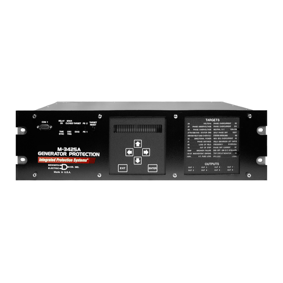
RESET PS 2 PS 1 PS 2 TARGET DIAG BRKR OSC. TRIG CLOSED PS 1 RELAY TIME SYNC PS 2 COM 1 M-3425A 3 A MP, 250V, GENERATOR (3A B) PROTECTION PS 1 Figure 8 M-3425A Vertical Unit Layout –25–... - Page 27 M‑3425A Generator Protection Relay 0.35 18.31 [0.89] [46.51] NOTES: 1. Dimensions in brackets are in centimeters. 2. See Instruction Book Chapter 5 for Mounting and Cutout information. Figure 9 Horizontal and Vertical Unit Dimensions With Expanded I/O (H5 and H6) –26–...
- Page 28 PS 1 Made in U.S.A. NOTES: 1. The M-3425A Expanded I/O vertical panel is the same physical size as the M-3425A Expanded I/O horizontal panel. See Figure 7 for dimennsions. 2. See Instruction Book Section 5 for Mounting and Cutout information.
- Page 29 M‑3425A Generator Protection Relay M‑3921 Field Ground Coupler PROTECTION RELAY M-3425A PROCESSOR Excitation System Field Ground Brushes Detection Squarewave Gen. Generator Rotor COUPLING Signal NETWORK Measurement (M-3921) and Processing Shaft Ground Brush Ground/Machine Frame Figure 11 Field Ground Protection Block Diagram ...
- Page 30 M‑3425A Generator Protection Relay Tests and Standards M‑3921 Field Ground Coupler complies with the following tests and standards: Voltage Withstand Isolation 5 kV ac for 1 minute, all terminals to case Impulse Voltage 5,000 V pk, 1.2 by 50 µs, 0.5 J, 3 positive and 3 negative impulses at 5 second IEC 60255–5, intervals per minute Electrical Interference...
- Page 31 M‑3425A Generator Protection Relay Figure 12 M-3921 Field Ground Coupler Mounting Dimensions –30–...
- Page 32 M‑3425A Generator Protection Relay 64S 100% Stator Ground Protection by Low Frequency Signal Injection NOTE: The Stator Ground Protection function (64S) must be selected when the M‑3425A is initially ordered. The 100% stator ground fault protection is provided by injecting an external 20 Hz signal into the neutral of the generator.
- Page 33 M‑3425A Generator Protection Relay Figure 13 64S Function Component Connection Diagram (Model A00/EE 20 Hz Signal Generator) –32–...
- Page 34 M‑3425A Generator Protection Relay 20 Hz Signal Generator Function Specifications Auxiliary Voltage Rated auxiliary voltage U 3x (100/120 V ac), 50/60 Hz 1x (100 to 120 V ac), 50/60 Hz Permissible variations ac 88 to 230 V ac Rated auxiliary voltage U 110 to 220 V dc Permissible Variations dc 88 to 250 V dc...
- Page 35 M‑3425A Generator Protection Relay Dimensions in mm NOTE: Detailed Mounting information is contained in the M‑3425A Instruction Book Chapter 5, Installation Section 5.6. Figure 14 20Hz Signal Generator Dimensions –34–...
- Page 36 M‑3425A Generator Protection Relay Band‑pass Filter Specifications Load Capacity of the 20 Hz Band-pass Filter Connections (1B1‑1B4) Permissible voltage, continuous 55 V ac Permissible voltage for O30 s 550 V ac Frequency of superimposed ac voltage P 45 Hz Overload capability, continuous 3.25 A ac Test Voltage 2.8 kV dc...
- Page 37 M‑3425A Generator Protection Relay NOTE: Detailed Mounting information is contained in the M‑3425A Instruction Book Chapter 5, Installation Section 5. Figure 15 Band‑pass Filter Dimensions Figure 16 20 Hz Measuring Current Transformer 400‑5 A CT –36–...
- Page 38 This Page Left Intentionally Blank...
- Page 39 © 2001 Beckwith Electric Co. All Rights Reserved. 800-3425A-SP-10MC2 07/12 Printed in U.S.A. (#01-67) (04.25.03)
- Page 40 WARNING DANGEROUS VOLTAGES, capable of causing death or serious injury, are present on the external terminals and inside the equip- ment. Use extreme caution and follow all safety rules when han- dling, testing or adjusting the equipment. However, these internal voltage levels are no greater than the voltages applied to the exter- nal terminals.
- Page 41 PRODUCT CAUTIONS Before attempting any test, calibration, or maintenance procedure, personnel must be completely familiar with the particular circuitry of this unit, and have an adequate understanding of field effect devices. If a component is found to be defective, always follow replacement procedures carefully to that assure safety features are maintained.
- Page 42 NOTE The following features, described in this Instruction Book, are only available for firmware version D-0150-V01.00.34 and later: 59N 20 Hz Injection Mode (Page 2-58) IEEE curves for 51N, 51V, and 67N functions (Appendix D) Sequence of Events Recorder (Page 4-18) Dropout/Reset Time Delay added to IPSlogic (Page 2-91) Response Time Delay for Communications (Page 4-3) 25 Function (does not produce a target) (Page 2-21)
- Page 43 This Page Left Intentionally Blank...
-
Page 44: Table Of Contents
TABLE OF CONTENTS M-3425A Generator Protection Instruction Book Chapter 1 Introduction Instruction Book Contents ................1–1 M-3425A Generator Protection Relay ............1–2 Communication Ports ...................1–3 S-3400 IPScom Communications Software ..........1–4 Accessories ....................1–4 M-3925A Target Module ................1–4 M-3931 Human-Machine Interface (HMI) Module .........1–5 ®... - Page 45 M-3425A Instruction Book Chapter 2 Operation (Cont.'d) Clear Targets ....................2–16 Oscillograph Recorder Data ................2–16 Oscillograph Recorder (From IPScom) ............2–19 Retrieve Oscillograph Records ................ 2–19 Trigger Oscillograph ..................2–20 Clear Oscillograph Records ................2–20 Software Version (Relay Front Panel only) ............2–21 Serial Number (Relay Front Panel only) ............
- Page 46 System Setpoints ..................... 4–39 Setpoint Profiles (Setting Groups) ..............4–39 Configure Relay Data ..................4–39 Functions ......................4–40 Special Considerations ..................4–41 21 Phase Distance ..................4–46 24 Overexcitation Volts/Hz ................4–50 M-3425A Firmware Versions D-0114VXX.XX.XX and Earlier ......4–51...
- Page 47 M-3425A Instruction Book Chapter 4 System Setup and Setpoints (Cont.'d) M-3425A Firmware Version D-0150V 01.00.34 ..........4–51 M-3425A Firmware Version D-0150V 01.04.00 ..........4–51 25 Sync Check....................4–53 Phase Angle Check ..................4–53 Delta Voltage and Delta Frequency Check ............4–53 27 Phase Undervoltage ...................
- Page 48 Table of Contents Chapter 5 Installation General Information ................... 5–1 Service Conditions and Conformity to CE Standard .......... 5–1 Mechanical/Physical Dimensions ..............5–2 External Connections ..................5–8 Power Supply ..................... 5–8 Grounding Requirements .................. 5–8 Unit Isolation ...................... 5–8 Insulation Coordination ..................5–8 Torque Requirements ..................
- Page 49 Chapter 1 1-1 M-3925A Target Module ...............1–4 1-2 M-3931 Human-Machine Interface (HMI) Module ....... 1–5 Chapter 2 2-1 M-3425A Front Panel ................2–4 2-2 Screen Message Menu Flow ...............2–6 2-3 Main HMI Menu Flow ................2–7 2-4 Primary Metering & Status Screen ............2–10 2-5 Secondary Metering &...
- Page 50 Table of Contents Figures (Cont.'d) Page Chapter 3 3-1 IPScom Program Icon ................3–1 3-2 IPScom Main Screen ................3–2 3-3 S-3400 IPScom Menu Selection ............... 3–3 3-4 New System Dialog Screen ..............3–4 3-5 IPScom Serial Communication Dialog Screen ......... 3–5 3-6 IPScom TCP/IP Ethernet Communication Dialog Screen ......
- Page 51 M-3425A Instruction Book Figures (Cont.'d) Page Chapter 4 4-1 Change Comm Access Code Dialog Screen ........4–4 4-2 Access Code Change Confirmation Screen ..........4–4 4-3 Access Code Changed Confirmation Screen ........4–4 4-4 Access Level Code Dialog Screen ............4–6 4-5 Change User Access Code Dialog Screen ...........4–6 4-6 User Information Dialog Screen ............4–8...
- Page 52 Table of Contents Figures (Cont.'d) Page Chapter 4 (Cont.'d) 4-43 Directional Power, 3-Phase (32) Setpoint Ranges ......4–64 4-44 Loss of Field (40)—Protective Approach 1 ........4–66 4-45 Loss of Field (40)—Protective Approach 2 ........4–67 4-46 Loss-of-Field (40) Setpoint Ranges ..........4–67 4-47 Negative Sequence Overcurrent Inverse Time Curves .....4–69 4-48 Negative Sequence Overcurrent (46) Setpoint Ranges ....4–69 4-49 Time Constant, Function 49 ..............4–70 4-50 49 Function Overload Curves ............4–71...
- Page 53 Without Expanded I/O (H1) ..............5–2 5-2 M-3425A Vertical Chassis Mounting Dimensions Without Expanded I/O (H2) ..............5–3 5-3 M-3425A Mounting Dimensions Horizontal and Vertical Chassis With Expanded I/O ................5–4 5-4 M-3425A Panel Mount Cutout Dimensions ...........5–5 5-5 Mounting Dimensions for GE L-2 Cabinet H3 and H4 ......5–6 5-6 (H5) Mounting Dimensions..............5–7...
- Page 54 Table of Contents Figures (Cont.'d) Page Chapter 6 6-1 Voltage Inputs: Configuration V1 ............6–3 6-2 Voltage Inputs: Configuration V2 ............6–3 6-3 Current Inputs: Configuration C1 ............6–4 6-4 Current Inputs: Configuration C2 ............6–4 6-5 Current Configuration C3 ..............6–5 6-6 64S Test Configuration ................6–5 6-7 Field Ground Coupler................6–45 6-8 Status LED Panel ................6–71 6-9 M-3925A Target Module Panel ............6–72...
- Page 55 F-14 Setup Unit (1 of 2) ................F–26 F-15 Diagnostic Mode (1 of 2) ..............F–28 Tables Page Chapter 1 1-1 M-3425A Device Functions ..............1–3 Chapter 2 2-1 Recorder Partitions ................. 2–16 Chapter 4 4-1 Dead-Sync Time ..................4–15 4-2 Recorder Partitions ................. 4–24 4-3 Input Activated Profile Logic ..............
- Page 56 C-1 Self-Test Error Codes ................C–1 ® C-2 IPScom Error Messages ............... C–2 Appendix D D-1A M-3425A Inverse Time Overcurrent Relay Characteristic Curves ..D–6 Appendix H H-1 Declaration of Conformity ................ H–2 ©1998 Beckwith Electric Co. All Rights Reserved. 800-3425A-IB-09 07/12 Printed in U.S.A.
- Page 57 M-3425A Instruction Book This Page Left Intentionally Blank...
-
Page 58: Chapter 1 Introduction
M-3425A. the system. It describes the procedures for entering all required data into the M-3425A. Included in this chapter are functional and connection diagrams for Chapter 2: Operation a typical application for the system;... -
Page 59: M-3425A Generator Protection Relay
Inverse Time Curves for V/Hz applications, the four functions from the M-3425A front panel using a menu- standard and the four IEC overcurrent curves. Also driven, 2 line by 24 character alphanumeric display: included are three IEEE inverse time curves. -
Page 60: Communication Ports
Volts/Hz (Inverse & Definite Time) operation for the most recent event. Phase Undervoltage The M-3425A retains up to 416 cycles of oscillograph 27TN Third Harmonic Undervoltage, Neutral waveform data assignable to up to 24 events with Directional Power selectable post-trigger delay. -
Page 61: S-3400 Ipscom Communications Software
SPLIT PHASE DIFF 50DT 59N/59X NEUT/GND OVERVOLT STATOR OVERLOAD S‑3400 IPScom Communications Software DIRECTIONAL POWER NEG SEQ OVERCURRENT46 Each M-3425A unit includes the S-3400 PHASE DISTANCE FIELD GND/BRUSH LIFT64F/B LOSS OF FIELD FREQUENCY 81/81R/81A IPScom Communications Software. The IPScom OUT OF STEP... -
Page 62: M-3931 Human-Machine Interface (Hmi) Module
Operation of the module is described in detail in Section 2.1, Front Panel Controls and 2000 or later, to enable the plotting and printing Indicators. of waveform data downloaded from the M-3425A Generator Protection Relay. M‑3933/M‑0423 Serial Communications Cable The M-3933 cable is a 10-foot straight-through RS-232 modem cable for use between the relay’s... - Page 63 M‑3425A Instruction Book This Page Left Intentionally Blank 1–6...
- Page 64 Front Panel Controls and Indicators ........2–3 Operation (HMI/PC) ..............2–5 This chapter contains information that describes the operation of the M-3425A Generator Protection Relay. See Chapter 4 for System Setup, Configuration and Setpoint information. M-3425A operation from either IPScom or HMI includes the following: •...
-
Page 65: Chapter 2 Operation
M‑3425A Instruction Book Chapter 2 - Operation ® 2.1 Front Panel Controls and Indicators ..3 View Target History (From IPScom ) ...15 Alphanumeric Display ........3 View Targets ..........15 Screen Blanking ..........3 Clear Targets ..........16 Arrow Pushbuttons ..........3 Oscillograph Recorder Data ......16 EXIT Pushbutton ..........3 Oscillograph Recorder (From IPScom) ..19 ENTER Pushbutton .........3... -
Page 66: Front Panel Controls And Indicators
The EXIT pushbutton is used to exit from a displayed screen and move up the menu tree. Any changed This section describes the operation of the M-3425A setpoint in the displayed screen will not be saved if the selection is aborted using the EXIT pushbutton. -
Page 67: Power Supply (Ps1) And (Ps2) Leds
M‑3425A Instruction Book Power Supply (PS1) and (PS2) LEDs M-3925A Target Module and Target Reset Push- button The green power LED indicator (for the appropriate For units equipped with the optional M-3925A power supply) will be illuminated whenever power is Target Module, additional targeting information is applied to the unit and the power supply is functioning available. -
Page 68: Operation (Hmi/Pc)
Whenever power is applied to the unit the Power On Self Test sequence is initiated (Figure 2-2). The purpose of this section is to describe the steps that are necessary to interrogate the M-3425A utilizing Default Message Screens either the optional M-3931 HMI or a PC running ®... -
Page 69: Hmi Security
Depending on the access code each level holds, users have varying levels of access to the relay functions. Level 3 Access: provides access to all M-3425A configuration functions and settings. Level 2 Access: provides access to read & change setpoints, monitor status and view target history. -
Page 70: Main Hmi Menu Flow
Operation – 2 STATUS VOLTAGE RELAY SYNC CHECK RELAY config sys STAT VOLT curr freq v/hz field stator SYNC Voltage Status 25S Sync Check • 27 Phase Undervoltage Current Status 25D Dead Volt • 59 Phase Overvoltage ... -
Page 71: Status Monitoring (From Relay Front Panel)
M‑3425A Instruction Book Status Monitoring (From Relay Front Panel) To access the STATUS menu and begin monitoring, proceed as follows: The menu categories for monitored values are: Press the ENTER pushbutton. • Voltage Status: phase voltages, neutral voltage, positive sequence voltage, If Level Access is active, the following is negative sequence voltage, zero sequence displayed:... -
Page 72: Status Monitoring (From Ipscom ® )
Operation – 2 ® Status Monitoring (From IPScom PRIMARY METERING & STATUS To access the PRIMARY METERING & STATUS Also included on the Primary Metering & Status parameters utilizing IPScom, select Monitor/Primary screen are: Metering & Status from the IPScom Main Screen drop •... -
Page 73: Primary Metering & Status Screen
M‑3425A Instruction Book Path: Monitor / Primary Metering & Status Figure 2‑4 Primary Metering & Status Screen 2–10... -
Page 74: Secondary Metering & Status
Operation – 2 SECONDARY METERING & STATUS • Low Frequency Injection To access the SECONDARY METERING & VN (V) ® STATUS parameters utilizing IPScom , select IN (mA) Monitor/Secondary Metering & Status from the Real (mA) IPScom Main Screen drop down menu. Monitor/Secondary Metering and Status •... -
Page 75: Secondary Metering & Status Screen
M‑3425A Instruction Book Path: Monitor / Secondary Metering & Status Figure 2‑5 Secondary Metering & Status Screen 2–12... -
Page 76: View Target History
VIEW TARGET HISTORY b. If the proper Access Code has been entered, the HMI will return: The M-3425A Generator Protection Relay includes the ability to store the last 32 target conditions in a LEVEL #(1,2 or 3) nonvolatile memory. A target is triggered whenever Access Granted! an output is operated. - Page 77 M‑3425A Instruction Book This screen displays operated outputs. This screen displays the phase current at the time the target operated. Target 1 TARGET 1 N=0.50 AMPS This screen displays operated inputs at time of trip. This screen displays the neutral current at the time the target operated.
-
Page 78: View Target History (From Ipscom ® )
Operation – 2 ® Press the ENTER pushbutton, the View Target History (From IPScom following will be displayed: View Targets To View Targets select Relay/Targets/View. VIEW TARGET HISTORY IPScom will display the View Targets screen (Figure TRGT clear 2-6). The View Targets screen includes the following target information: Press the Right arrow pushbutton until •... -
Page 79: Clear Targets
M‑3425A Instruction Book Clear Targets When triggered, the time stamp is recorded, and the recorder continues recording for a To Clear Targets perform the following: user-defined period. The snapshot of the Select Relay/Targets/Clear. IPScom will waveform is stored in memory for later display the Clear Targets confirmation retrieval using IPScom Communications dialog screen (Figure 2-7). - Page 80 Operation – 2 To access the Oscillograph Recorder VIEW RECORDER STATUS feature, proceed as follows: Press the ENTER pushbutton. Press the ENTER pushbutton, the following will be displayed: If Level Access is active, the following is displayed: VIEW RECORDER STATUS STAT clear setup...
- Page 81 M‑3425A Instruction Book To access the Oscillograph Recorder CLEAR RECORDS feature, proceed as follows: Press the ENTER pushbutton. Press the ENTER pushbutton, the following will be displayed: If Level Access is active, the following is displayed: VIEW RECORDER STATUS ENTER ACCESS CODE STAT clear setup...
-
Page 82: Oscillograph Recorder (From Ipscom)
Operation – 2 Oscillograph Recorder (From IPScom) Upon completion of the oscillograph NOTE: Oscillograph Recorder Setup (See file download, IPScom will display the Download Successful Confirmation Chapter 4, System Setup and Setpoints) screen (Figure 2-11). Retrieve Oscillograph Records To retrieve Oscillograph Records perform the following: Select Relay/Oscillograph/Retrieve. -
Page 83: Trigger Oscillograph
M‑3425A Instruction Book Trigger Oscillograph Clear Oscillograph Records To manually Trigger the Oscillograph perform the To Clear Oscillograph Records perform the following: following: Select Relay/Oscillograph/Clear. Select Relay/Oscillograph/Trigger. I P S c o m w i l l d i s p l ay t h e C l e a r ®... -
Page 84: Software Version (Relay Front Panel Only)
Operation – 2 Software Version (Relay Front Panel only) Serial Number (Relay Front Panel only) To determine the software version installed on the To determine the serial number of the relay, proceed relay, proceed as follows: as follows: Press the ENTER pushbutton. Press the ENTER pushbutton. -
Page 85: Alter Access Codes (From Relay Front Panel)
M‑3425A Instruction Book Press the ENTER pushbutton, the Alter Access Codes (From Relay Front Panel) following will be displayed: Press the ENTER pushbutton. If Level Access is active, the following is SERIAL NUMBER displayed: XXXXXXXXXX ENTER ACCESS CODE To exit press the EXIT pushbutton. a. - Page 86 Operation – 2 Press ENTER, the following will be Repeat Step 9 to enter the desired Level displayed: #2 User Access Code. To set User Access Code Level #3 ENTER ACCESS CODE press the RIGHT arrow pushbutton to LEVEL#1 level#2 level#3 select LEVEL #3, then press ENTER the following will be displayed: Press ENTER, the following will be...
-
Page 87: Alter User Access Codes (From Ipscom ® )
M‑3425A Instruction Book ® Alter User Access Codes (From IPScom Select Yes, IPScom will display an Access Code Was Changed Successfully Comm Access Codes Confirmation Screen (Figure 2-18). To set the relay Comm Access Code perform the following: NOTE: Communication must be established with the target relay for this procedure. -
Page 88: User Access Codes
Operation – 2 User Access Codes User Access Codes The relay includes three levels of access codes. To change the relay User Access Codes perform Depending on their assigned code, users have the following: varying levels of access to the installed functions. ... -
Page 89: System Error Codes, Output And Alarm Counters
M‑3425A Instruction Book System Error Codes, Output and Alarm Counters The System Error Codes, Output and Alarm Counters feature provides the user with the ability to view and clear system Error Codes, Processor Resets, Alarm Counters, Power Loss Counter and Output Counters. -
Page 90: Clear Alarm Counters (Relay Front Panel)
Operation – 2 Clear Alarm Counters (Relay Front Panel) To clear Alarm Counters from the Front Panel perform the following: Press the ENTER pushbutton. Press the Right arrow pushbutton until the following is displayed: If Level Access is active, the following is displayed: CLEAR OUTPUT COUNTERS logo1 logo2 out ALRM V... -
Page 91: Clear Error Codes (Relay Front Panel)
M‑3425A Instruction Book Clear Error Codes (Relay Front Panel) To clear Error Codes from the Front Panel perform the following: Press the ENTER pushbutton. Press ENTER, the following will be displayed: If Level Access is active, the following is displayed: SOFTWARE VERSION VERS sn access number V ENTER ACCESS CODE... -
Page 92: Resetting Counters (From Ipscom)
Operation – 2 Resetting Counters (From IPScom) Tools/Counters and Error Codes To view and/or Reset System Error Codes and ® Output Counters utilizing IPScom perform the following: NOTE: Communication must be established with the target relay for this procedure. From the IPScom Main Screen menu bar select Tools/Counters and Error Codes. -
Page 93: Relay/Sequence Of Events/Retrieve
M‑3425A Instruction Book Relay/Sequence of Events/Retrieve To download available Sequence of Events perform the following: The Retrieve selection downloads the events from the currently connected relay (events must be From the IPScom Main Screen menu select Relay/Sequence of Events/ retrieved from the relay and stored in a file in order Retrieve. -
Page 94: Relay/Sequence Of Events/View
Operation – 2 Relay/Sequence of Events/View Relay/Sequence of Events/Clear The Sequence of Events viewer screen includes The Clear feature clears all Sequence of Events the commands Open, Close, Print Summary, and Records stored on the relay. Print. Open opens a saved sequence of events file. To Clear all Sequence of Events Records perform Close closes the print file. - Page 95 M‑3425A Instruction Book This Page Left Intentionally Blank 2–32...
-
Page 96: Chapter 3 Ipscom
Connect and Help menu selections. This menu bar system settings and operational commands to includes the additional selections; Communication, the M-3425A as well as access the extensive Monitor, System, Tools and Windows when monitoring and status reporting features. Figure IPScom is in either the file mode or has open 3-3, represents the IPScom Main Screen menu communications established with a relay. - Page 97 M‑3425A Instruction Book Figure 3-2 IPScom Main Screen 3–2...
- Page 98 IPScom – 3 ® Figure 3-3 S-3400 IPScom Menu Selection 3–3...
-
Page 99: File Menu
File/Close Command Closes the open file without saving. File/New Command When not connected to a M-3425A, using the New File/Exit Command command, a new file is established with the New The Exit command quits the IPScom program. -
Page 100: Connect\Communication Menu
IPScom – 3 ® Connect\Communication Menu If the modem was not used to establish communication (direct connection), select Connect to start. If the relay has a default communication access code of 9999, a message window will be displayed showing Access Level #3 was granted. Otherwise, another dialog screen will be displayed to prompt the user to enter the access code in order to establish communication. -
Page 101: Communication\Open Terminal Window
M‑3425A Instruction Book Communication\Open Terminal Window Opens the IPScom Terminal Window (Figure 3-8). Figure 3-7 IPScom Modem Communication Dialog Screen Figure 3-8 Terminal Window 3–6... -
Page 102: Monitor Menu
IPScom – 3 ® Monitor Menu • Frequency The Monitor Menu provides access to the screens used to monitor relay parameters. Seven submenus V/Hz (%) are provided: Primary Metering and Status, Secondary Metering and Status, Accumulator ROCOF (Hz/s) Status, Phasor Diagram, Phase Distance, Loss of Field, Out of Step, Sync Scope, Function •... - Page 103 M‑3425A Instruction Book Path: Monitor / Primary Metering and Status Figure 3-9 Primary Metering Status Screen 3–8...
-
Page 104: Monitor/Secondary Metering & Status
IPScom – 3 ® Monitor/Secondary Metering & Status The Secondary Metering and Status screen (Figure 3-10) allows the user to review the following SECONDARY parameters: • Voltages • 3rd Harmonic VN (V) VX (V) VX/VN Neutral • Power Positive Sequence Real Negative Sequence Reactive... - Page 105 M‑3425A Instruction Book Path: Monitor / Secondary Metering and Status Figure 3-10 Secondary Metering Status Screen 3–10...
-
Page 106: Monitor/Accumulator Status
IPScom – 3 ® Monitor/Accumulator Status for the next band, i.e., Low Band #2 is the upper limit for Band #3, and so forth. Frequency bands Frequency Accumulation feature provides an must be used in sequential order, 1 to 6. Band #1 indication of the amount of off frequency operation must be enabled to use Bands #2–#6. -
Page 107: Monitor/Phasor Diagram
M‑3425A Instruction Book Monitor/Phasor Diagram The Phasor Diagram (Figure 3-12) provides the user with the ability to evaluate a reference Phase Angle to Phase Angle data from other windings. The Phasor Diagram also includes a menu that allows the user to select/deselect sources to be displayed and Freeze capability to freeze the data displayed on the Phasor Diagram. -
Page 108: Monitor/Phase Distance Diagram
IPScom – 3 ® Monitor/Phase Distance Diagram The Phase Distance Diagram (Figure 3-13) provides the user with a graphic representation to evaluate Phase Distance settings for all three phases. See Function 21, Phase Distance in Chapter 4 for additional information. Path: Monitor / Phase Distance Diagram ... -
Page 109: Monitor/Loss Of Field
M‑3425A Instruction Book Monitor/Loss of Field The Loss of Field Diagram (Figure 3-14) displays a graphic representation of Loss of settings, and also displays the Positive Sequence Impedance. See Function 40, Loss of Field in Chapter 4 for additional information. Path: Monitor / Loss of Field Figure 3-14 Loss of Field Diagram... -
Page 110: Monitor/Out Of Step
IPScom – 3 ® Monitor/Out of Step The Out of Step graphic representation provides the user with the ability to evaluate Out of Step settings. See Function 78, Out of Step in Chapter 4 for additional information. Path: Monitor / Out of Step Figure 3-15 Out of Step Diagram 3–15... -
Page 111: Monitor/Sync Scope
See Function 25, Sync Check in Chapter 4 for additional information. Path: Monitor / Sync Scope Figure 3-16 Sync Scope s CAUTION: The M-3425A Sync Scope should not be used to determine phase conditions for manual synchronizing because of possible communications time delay. 3–16... -
Page 112: Monitor/Function Status
IPScom – 3 ® Monitor/Function Status The Function Status screen displays the status of various functions, with a red circle indicating functions that have tripped, and a green circle for those functions that have picked up and are timing. Also displayed are Active Inputs and Outputs. -
Page 113: Monitor/87 Dual Slope
M‑3425A Instruction Book Monitor/87 Dual Slope The 87 Dual Slope display allows the user to display a graphical representation of the 87 programmable Dual Slope Percentage Restraint Characteristic. See Function 87, Phase Differential Current in Chapter 4 for additional information. Path: Monitor / 87Dual Slope Figure 3-18 87 Function Dual Slope Display... -
Page 114: Relay Menu
IPScom – 3 ® Relay Menu The Setup submenu includes the Setup System, Relay Setpoints, Set Date &Time, Display I/O Map and Display All Setpoints selections. Relay/Setup/Setup System The Setup System selection displays the Setup System dialog screen (Figures 3-19, 3-20 and 3-21) allowing the user to input the pertinent information regarding the system on which the relay is applied (see Section 4.2, Setup System, for detailed... - Page 115 M‑3425A Instruction Book Path: Relay / Setup / Setup System Figure 3-20 Setup System/System/I/O Setup Dialog Screen Path: Relay / Setup / Setup System Figure 3-21 Setup System/Output Seal-in Time Dialog Screen 3–20...
-
Page 116: Relay/Setup/Relay Setpoints
IPScom – 3 ® Relay/Setup/Relay Setpoints The Relay Setpoints menu selection displays the Relay Setpoints dialog screen (Figure 3-22) from which the individual Function Setting dialog screens can be accessed. Selecting a Function Setting button will display the corresponding function dialog screen (See Figure 3-23 as an example). Figure 3-22 Relay Setpoints Dialog Screen COMMAND BUTTONS Display All Setpoints... - Page 117 M‑3425A Instruction Book Figure 3-23 Example Function Dialog Screen COMMAND BUTTONS Save When connected to a relay, sends the currently displayed information to the unit. Otherwise, saves the currently displayed information and returns to the System Setpoints screen or All Setpoints Table. Cancel Returns to the System Setpoints screen or All Setpoints Table;...
-
Page 118: Relay/Setup/Set Date & Time
IPScom – 3 ® Relay/Setup/Set Date & Time The Setup Date & Time command (Figure 3-24) allows the system date and time to be set, or system clock to be stopped. The system clock is used for Time and Date Stamping when the Time Sync is not available. -
Page 119: Relay/Setup/Display/I/O Map
M‑3425A Instruction Book Relay/Setup/Display/I/O Map Both the Relay Setpoints dialog screen and the I/O Map screen include the Display All Setpoints Selecting the I/O Map button displays the I/O Map feature and Jump Command Buttons which allow dialog screen (Figure 3-25), which contains a chart the user to jump from a scrolling dialog screen to an of programmed input and output contacts, in order to individual relay function dialog screen and return to... -
Page 120: Relay/Setup/Display All Setpoints
IPScom – 3 ® Relay/Setup/Display All Setpoints Selecting the Display All Setpoints button displays The All Setpoint Table includes Jump Command the All Setpoints dialog screen (Figures 3-26). This Buttons which allow the user to jump from a scrolling dialog screen contains the settings for each relay dialog screen to an individual relay function dialog screen and return to the scrolling dialog screen. -
Page 121: Relay/Targets
M‑3425A Instruction Book Relay/Targets The Targets submenu provides three command options: View, Clear and Reset LED. The View command displays the View Targets Dialog Screen (see Figure 3-27). This dialog screen provides detailed data on target events including time, date, function status, phase current values, and IN/ OUT contact status at the time of trip. -
Page 122: Relay/Sequence Of Events
IPScom – 3 ® Relay/Sequence of Events The Sequence of Events submenu allows the user to Setup, Retrieve, View and Clear Sequence of Events records. The Setup command displays the Setup Sequence of Events Recorder dialog screen (Figure 3-28). Function Pickup, Trip and Dropout can be selected to initiate the recorder as well as Input Pickup, Output Pickup, Inputs Drop and Outputs Drop. - Page 123 M‑3425A Instruction Book Figure 3-30 View Sequence of Events Recorder Screen 3–28...
-
Page 124: Relay/Oscillograph
IPScom – 3 ® Relay/Oscillograph The Oscillograph submenu allows setting and control over the relay’s oscillograph recorder. The Setup command allows the user to set the number of partitions and triggering designations to be made (Figure 3-31), Retrieve downloads and save data to a file (Figure 3-32). -
Page 125: Relay/Profile
M‑3425A Instruction Book Relay/Profile The Profile submenu provides three command options: Switching Method, Select Profile, and Copy Active Profile. The Switching Method command allows selection of either Manual or Input contact (Figure 3-33). Select Profile allows the user to designate the active profile (Figure 3-34). -
Page 126: Relay/Write File To Relay
IPScom – 3 ® Relay/Write File to Relay Tools/Security The Security menu item includes the Change Comm Access Code and Change User Access Code submenus. Tools/Security/ Change Comm Access Code The Change Comm Access code selection displays the Change Comm Access Code screen (Figure 3-38) which allows the user to change the Comm Access Code. -
Page 127: Tools/Security/Change User Access Code
M‑3425A Instruction Book Tools/Security/Change User Access Code Tools/User Information The Change User Access Code selection displays The User Information menu selection displays the Change User Access Code screen (Figure the User Information screen (Figure 3-40) which 3-39) which allows the user to change the relay provides the user with the ability to edit/input the User Access Code. -
Page 128: Tools/Relay Communication
IPScom – 3 ® Tools/Relay Communication The Relay Communication menu selection provides the user with the ability to change the relay Communication Address (Figure 3-41), set the relay’s COM Port communication parameters (Figure 3-42) and setup the Ethernet Port (Figure 3-43). -
Page 129: Tools/Counters And Error Codes
M‑3425A Instruction Book Tools/Counters and Error Codes The Counters and Error Codes menu selection displays the Counters and Error Codes screen (Figure 3-46) which provides the user with the ability to view and clear system Error Codes, Alarm Counters, Power Loss Counter and Output Counters. -
Page 130: Tools/Firmware Update
An Adobe Acrobat reader Dialog Screen is required to view this document. The M-3425A Instruction Book has been indexed Tools/Calibration Data to its table of contents. By selecting the ‘Navigator The Calibration Data feature allows the user to pane’... - Page 131 M‑3425A Instruction Book This Page Left Intentionally Blank 3–36...
-
Page 132: Chapter 4 System Setup And Setpoints
If additional link security is desired, a communication access code can be programmed. Like the user access codes, if the communication access code The selection of the M-3425A System Setup is set to 9999 (default), communication security is parameters and Setpoints can be performed using disabled. - Page 133 HMI SET DATE and TIME ......12 21 Phase Distance ........46 Communication Setup ........14 24 Overexcitation Volts/Hz ......50 Serial Ports (RS-232) ........14 M-3425A Firmware Versions D-0114VXX.XX.XX and Earlier .....51 Serial Port (RS-485) ........14 M-3425A Firmware Version Direct Connection ..........14 D-0150V 01.00.34 .........51 Device Address ..........14...
- Page 134 System Setup and Setpoints – 4 Protection from Excessive Reactive Power ..61 87GD Ground (Zero Sequence) Differential ...........117 40 Loss of Field ..........65 Breaker Monitoring ........118 46 Negative Sequence Overcurrent ....68 Trip Circuit Monitoring .........119 49 Stator Overload Protection ......70 IPSlogic™...
- Page 135 M‑3425A Instruction Book IPScom Comm Access Code Setup Select Yes, IPScom will display an Access Code Was Changed Successfully To set the relay Comm Access Code perform the Confirmation Screen (Figure 4-3). following: NOTE: Communication must be established with the target relay for this procedure.
-
Page 136: Chapter 4 - System Setup And Setpoints
System Setup and Setpoints – 4 HMI Comm Access Code Setup Press the ENTER pushbutton. Press the Right arrow pushbutton until the following is displayed: If Level Access is active, the following is displayed: COMM ACCESS CODE dly ACCSS eth eth_ip ENTER ACCESS CODE Press ENTER, the following will be displayed:... -
Page 137: Ipscom User Access Code Setup
M‑3425A Instruction Book IPScom User Access Code Setup Enter a valid Access Code, then select OK. IPScom will display the Change The relay includes three levels of access codes. User Access Code dialog screen Depending on their assigned code, users have (Figure 4-5). -
Page 138: Hmi User Access Codes Setup
System Setup and Setpoints – 4 HMI User Access Codes Setup ENTER ACCESS CODE Press the ENTER pushbutton. LEVEL#1 level#2 level#3 If Level Access is active, the following is displayed: Press ENTER, the following will be displayed: ENTER ACCESS CODE LEVEL #1 9999 Input the required Access Code, then... -
Page 139: User Logo Line
M‑3425A Instruction Book USER LOGO LINE HMI User Logo Line Setup Press the ENTER pushbutton. The user logo is a programmable, two-line by 24-character string, which can be used to identify the If Level Access is active, the following is relay, and which is displayed locally when the unit is displayed: idle. - Page 140 Press ENTER, the following will be displayed: displayed: USER LOGO LINE 1 USER LOGO LINE 2 _BECKWITH ELECTRIC CO. M-3425A Input the desired User Logo Line 1 as Input the desired User Logo Line 2 as follows: follows: Utilizing the Up and Down arrow...
-
Page 141: Hmi User Control Number Setup
M‑3425A Instruction Book HMI User Control Number Setup Press the Right arrow pushbutton until the following is displayed: Press the ENTER pushbutton. If Level Access is active, the following is USER CONTROL NUMBER displayed: vers sn access NUMBER V ENTER ACCESS CODE Press ENTER, the following will be displayed: Input the required Access Code, then... -
Page 142: Hmi System Ok Led Setup
System Setup and Setpoints – 4 HMI System OK LED Setup Press ENTER, the following warning will be displayed: Press the ENTER pushbutton. If Level Access is active, the following is PROCESSOR WILL RESET! displayed: ENTER KEY TO CONTINUE ENTER ACCESS CODE ▲... -
Page 143: System Clock
M‑3425A Instruction Book SYSTEM CLOCK HMI SET DATE and TIME Press the ENTER pushbutton. This feature allows the user to set the relay internal clock.The clock is used to time stamp system events If Level Access is active, the following is and oscillograph operations. - Page 144 System Setup and Setpoints – 4 Press ENTER, the following will be When the desired Day has been selected, then press ENTER. The displayed: following will be displayed: DATE & TIME 01 Year DATE & TIME 01 Hour Input the desired Year as follows: Utilizing the Up and Down arrow Input the desired Hour as follows: pushbuttons select the desired first...
-
Page 145: Direct Connection
Serial Port (RS-485) Communication Address COM3 located on the rear terminal block of To setup the COM Ports and Communication the M-3425A is an RS-485, 2-wire connection. Addresses perform the following: Appendix B, Figure B-3 illustrates a 2-wire RS- 485 network. - Page 146 System Setup and Setpoints – 4 From the IPScom Main Screen menu Enter the desired communications select Tools/Relay Communication/ Protocol (MODBUS, DNP3.0). Setup Comm Port. IPScom will display E n t e r t h e d e s i r e d “...
-
Page 147: Hmi Com Port Definitions And Device Address
M‑3425A Instruction Book HMI COM Port Definitions and Device Address Press ENTER. If setting up COM1, the screen will return to the beginning of the Press the ENTER pushbutton. Comm menu. If setting up COM2 or 3, If Level Access is active, the following is the following will be displayed: displayed: COM2 DEAD SYNC TIME... -
Page 148: Com Port Security
System Setup and Setpoints – 4 COM Port Security COM1, COM2 and COM3 may be disabled for security purposes from the unit HMI. A Level 2 Access Code is required. Disabling COM Ports Press the ENTER pushbutton. Press ENTER, the following will be displayed: If Level Access is active, the following is displayed:... -
Page 149: Ipscom Ethernet Port Setup With Dhcp
M‑3425A Instruction Book ETHERNET COMMUNICATION SETTINGS Protocol documents are available directly from Beckwith Electric or from our website The optional RJ45 Ethernet port can be enabled www.beckwithelectric.com. ® utilizing either IPScom from the Ethernet Settings menu or from the HMI Communication menu. When... -
Page 150: Hmi Ethernet Port Setup
System Setup and Setpoints – 4 HMI Ethernet Port Setup Press ENTER, the following will be Ensure that the Communication Menu is selected to COMM (upper case). displayed: COMMUNICATION DHCP PROTOCOL targets osc_rec COMM DISABLE enable If the network does not support the If COMM is not selected (Upper Case), then use the Right/Left arrow DHCP protocol, then go to Manual... -
Page 151: Manual Configuration Of Ethernet Board
M‑3425A Instruction Book Use the Right/Left arrow pushbuttons Manual Configuration of Ethernet Board to select the desired protocol (Upper Ensure that DISABLE is selected (Upper Case), then press ENTER, the following Case). will be displayed: If DISABLE is not selected (Upper Case), then use the Left arrow pushbutton to ETHERNET PROTOCOL select DISABLE. -
Page 152: Installing The Modems
System Setup and Setpoints – 4 INSTALLING THE MODEMS Use the Right/Left arrow pushbuttons to select the desired protocol (Upper ® Using IPScom to interrogate, set or monitor the Case), then press ENTER, the following relay using a modem requires both a remote modem will be displayed: connected at the relays location and a local modem connected to the computer with IPScom installed. -
Page 153: Initializing The Pc Modem
M‑3425A Instruction Book Initializing the PC Modem COMMAND BUTTONS Verify that the modem is connected Allows you to review and change as described in “Connecting the PC the user lines (unit identifier), Modem”. phone number, and communication address of a selected entry. Open IPScom, then select the Connect/ Modem menu item. -
Page 154: Connecting The Local Modem To The Relay
System Setup and Setpoints – 4 Connecting the Local Modem to the Relay Connect the Modem to the relay as follows: Setup of the modem attached to the relay may Connect the unit to an external modem by attaching a standard RS-232 be slightly complicated. -
Page 155: Oscillograph Setup
M‑3425A Instruction Book OSCILLOGRAPH SETUP NOTE: Oscillograph recorder settings are not considered part of the Setpoint Profile. The Oscillograph Recorder provides comprehensive Recorder settings are common to all data recording (voltage, current, and status input/ profiles. output signals) for all monitored waveforms (at 16 samples per cycle). -
Page 156: Ipscom Setup Oscillograph Recorder
System Setup and Setpoints – 4 IPScom Setup Oscillograph Recorder Select the Number of Partitions. NOTE: Communication must be established with The recorder’s memory may be the target relay for this procedure. When partitioned into 1 to 24 partitions. The not connected to the relay the Save relay Oscillograph Recorder memory selection does not save the Oscillograph... -
Page 157: Hmi Setup Oscillograph Recorder
M‑3425A Instruction Book HMI Setup Oscillograph Recorder Press the ENTER pushbutton. Press ENTER, the following will be displayed: If Level Access is active, the following is displayed: RECORDER PARTITIONS ENTER ACCESS CODE Input the desired number of Recorder Partitions. Input the required Access Code, then Press ENTER, the following will be press ENTER. -
Page 158: Ipscom Setup Sequence Of Events Recorder
System Setup and Setpoints – 4 IPScom Setup Sequence of Events Recorder To setup the Sequence of Events Recorder perform the following: Protective function Pickup, Trip, Dropout and/or Output/Input Pickup or Dropout are selected to From the IPScom Main Screen menu trigger the Sequence of Events Recorder. -
Page 159: Setup System
M‑3425A Instruction Book Setup System NOTE: Table 4-3 assumes ACTIVE INPUT STATE set to default setting (close circuit =TRUE). System setup data is required for proper operation Input 5 Input 6 Selection of the relay. Open Open Profile 1 The Setup System consists of defining common information like CT and VT ratios, nominal voltage Closed... - Page 160 Y by 30 degrees in Delta-AB. This screen allows the user to select the phase rotation of PHASE ROTATION the M-3425A to match the generator. a-c-b a-b-c This screen allows the selection of RMS or DFT for the 59 and 59/27 MAGNITUDE SELECT 27 functions.
- Page 161 M‑3425A Instruction Book LATCHED OUTPUTS If any of the outputs are selected as latched, then after tripping, this output will stay activated, even when the tripping o8 o7 o6 o5 o4 o3 o2 o1 condition is removed. The Latched Output can be reset using the TARGET RESET pushbutton.When selected, Pulse Relay is not available.
- Page 162 System Setup and Setpoints – 4 Figure 4-15 IPScom Relay Setup System Dialog Screen ® 4–31...
- Page 163 M‑3425A Instruction Book If neither Pulsed or Latched Output is enabled, the output contact will default to the normal mode. In this mode, the output contact will stay energized as long as the abnormal condition which caused it to operate persists. After the abnormal condition is cleared, the contact will reset after the programmed seal-in time has elapsed.
-
Page 164: System Diagrams
The 50BFN, 50N, 51N, 59D, 67N (with I or V ) and 87GD functions are unavailable when the 64S function has been purchased. See the M-3425A Instruction Book for connection details. Figure 4-18 One-Line Functional Diagram 4–33... - Page 165 The 50BFN, 50N, 51N, 59D, 67N (with I or V ) and 87GD functions are unavailable when the 64S function has been purchased. See the M-3425A Instruction Book for connection details. Figure 4-19 Alternative One-Line Functional Diagram (configured for split-phase differential) 4–34...
- Page 166 Application of external voltage on these inputs may result in damage to the units. NOTE : M-3425A current terminal polarity marks ( . ) indicate "entering" current direction when M-3425A primary current is "from" the generator to the Three VT Wye-Wye system.
- Page 167 M‑3425A Instruction Book M-3425A Used when Generator Side VTs are connected Line-Ground. Used for Sync Check (25) M-3425A Used when Generator Side VTs are connected Line-Line M-3425A M-3425A Three VT Wye-Wye Connection M-3425A Two VT Open-Delta Connection Generator NOTE: When V is connected for Sync Check function (25), turn-to-turn fault protection (59X) is not available.
- Page 168 System Setup and Setpoints – 4 M-3425A M-3425A used for turn-to-turn fault protection (59X) Generator Line to Neutral Voltage Rated Cable M-3425A M-3425A Low Impedance Grounding High Impedance Grounding NOTE: When V is connected for turn-to-turn faults 59X must use 3V0 for the line side voltage (i.e. setting selection) and the V.T.
- Page 169 M‑3425A Instruction Book Bus Section M-3425A input can be connected Residual CT either at Neutral or as Residual. M-3425A Connection M-3425A Bus Ground M-3425A 67N, 59D Connection can be used for both 67N and Generator 59D if connected in this manner.
-
Page 170: System Setpoints
System Setup and Setpoints – 4 Profile 2 will be identical to the “In Service” profile, System Setpoints with the exception of the overcurrent settings. Profile 1 is set to be the Active profile, and all setpoints The individual protective functions, along with their entered. -
Page 171: Functions
M‑3425A Instruction Book Functions Control/status input IN1 is preassigned to be the 52b breaker status contact. If a multiple breaker Configuration of the relay consists of enabling scheme is used, the control/status input IN1 must the functions for use in a particular application, be the series combination of the “52b”... -
Page 172: Special Considerations
System Setup and Setpoints – 4 Special Considerations FUNCTION DESCRIPTION Status input IN1 is pre-assigned to be the 52b Protective Functions breaker contact. IN5 and IN6 may be used to Phase Distance (three-zone mho select setpoint profiles (with input activated profiles characteristic) enabled). - Page 173 M‑3425A Instruction Book The Relay Setpoints command displays the Relay within a single window to allow scrolling through Setpoints dialog box (see Figure 4-24 from which all relay setpoint configuration values. Choosing the I/O Map command button displays the I/O Map the individual relay function dialog boxes can be dialog screen (Figure 4-27), which contains a accessed.
- Page 174 System Setup and Setpoints – 4 Figure 4-25 Negative Sequence Overcurrent Setpoint Dialog Screen Path: Relay menu / Setup submenu / Setpoints window/ 46 command button OR 46 jump hotspot within All Setpoints Table or Configure dialog screen COMMAND BUTTONS Save When connected to a protection system, sends the currently displayed information to the unit.
- Page 175 M‑3425A Instruction Book Figure 4-26 All Setpoints Table Dialog Screen Path: Relay menu / Setup submenu / Setpoints window/ Display All command button JUMP HOTSPOTS This window provides you with jump hotspots, identified by the hand icon, that take you to each relay dialog screen and the Setup Relay dialog screen.
- Page 176 System Setup and Setpoints – 4 Figure 4-27 I/O Map Screen Path: Relay menu / Setup submenu / Setpoints window/ I/O Map command button JUMP HOTSPOTS This window provides jump hotspots, identified by the hand icon, that take the user to each relay dialog screen and the Setup Relay dialog screen.
-
Page 177: Phase Distance
M‑3425A Instruction Book 21 Phase Distance When the generator is connected to the system through a delta/wye transformer, proper voltages and currents The Phase Distance function (21) is designed (equivalent to the high side of the transformer) must be for system phase fault backup protection and is used in order for the relay to see correct impedances implemented as a three-zone mho characteristic. - Page 178 System Setup and Setpoints – 4 21 #1 DIAMETER Typically the first zone of protection is set to an impedance value enough in excess of the first external protective section Ohms (typically the unit transformer) to assure operation for faults within that protective zone.
- Page 179 Protected Range Zone 3 Protected Range Zone 2 Protected Range Zone 1 M-3425A Figure 4-28 Phase Distance (21) Coverage NOTE: The reach settings of the distance elements (21) should not include generator impedance since the distance measurement starts at the VT location. However, since the neutral side CTs are used for this function, backup protection for generator Phase-to-Phase faults is also provided.
- Page 180 System Setup and Setpoints – 4 Figure 4-30 Phase Distance (21) Setpoint Ranges Transformer Direct Transformer Delta-AC Connected Transformer Delta-AB Connected Connected VT Connection VT Connection VT Connection L-L or L-G to L-L L-L or L-G to L-L L-L or L-G to L-L –...
-
Page 181: Overexcitation Volts/Hz
M‑3425A Instruction Book 24 Overexcitation Volts/Hz Setting this relay function involves determining the desired protection levels and operating times. The Volts-Per-Hertz function (24) provides The first step is to plot the combined generator overexcitation protection for the generator and unit- and associated unit transformer overexcitation connected transformers. -
Page 182: M-3425A Firmware Version D-0150V 01.00.34
#1 M-3425A Firmware Version D-0150V 01.00.34 The operating time of the inverse time The inverse time element has a definite minimum element at the definite time element time of 30 cycles. - Page 183 M‑3425A Instruction Book Figure 4-32 Volts-Per-Hertz (24) Setpoint Ranges 4–52...
-
Page 184: Sync Check
System Setup and Setpoints – 4 25 Sync Check Dead Line/Dead Bus Check NOTE: The 25 function cannot be enabled under The Dead Volt Limit defines the Hot/Dead voltage any one of the following conditions: level used in Deadline/Dead Bus closing schemes. When the measured V voltage is equal to or below •... - Page 185 M‑3425A Instruction Book If this function is enabled, the following settings are applicable: 25S PHASE LIMIT Phase angle setting. Degrees 25S UPPER VOLT LIMIT Upper voltage limit for voltage acceptance. Volts Lower voltage limit for voltage acceptance. 25S LOWER VOLT LIMIT Volts Sync check time delay.
- Page 186 System Setup and Setpoints – 4 Delta V and Delta F Check Logic With Delta V AND Delta F Enabled Only one Delta V and |V 1 - V X | < Delta V Limit Delta F Check Scheme may be active at a time. Delta V Is Enabled Phase Angle Check Logic |F 1 - F X | <...
- Page 187 M‑3425A Instruction Book Figure 4-34 Sync Check (25) Setpoint Ranges 4–56...
-
Page 188: Phase Undervoltage
System Setup and Setpoints – 4 27 Phase Undervoltage The Phase Undervoltage function (27) may be used Magnitude measurement depends on the 59/27 Magnitude Select setting (See Section 4.2, Setup to detect any condition causing long- or short-term undervoltage. This is a true three-phase function System). - Page 189 To properly handle pump storage operations, the equipment is required. The undervoltage inhibit M-3425A forward power blocking algorithm is setting should be about 80% to 90% of the nominal enable from “zero per unit” to the forward power voltage.
- Page 190 System Setup and Setpoints – 4 Low Band Forward Lag VAr Block Power Block Forward Block Block Reverse High Band Power Power Forward Block Block Power Block Lead VAr Block Figure 4-37 27TN Blocking Regions Figure 4-38 Third Harmonic Undervoltage, Neutral Circuit (27TN) Setpoint Ranges 4–59...
-
Page 191: 27Tn #2 Screens Are Identical To 27Tn #1
M‑3425A Instruction Book 27TN #2 Screens are identical to 27TN #1. Relay volts are equal to the primary neutral voltage divided by the grounding transformer ratio. Generally set for approximately 50% of the minimum third harmonic voltage observed during various loading conditions. -
Page 192: Directional Power
System Setup and Setpoints – 4 32 Directional Power power setting is set to Under and a positive pickup setting is chosen. The relay will trip when the The Directional Power function (32) can provide measured forward power is less than the pickup protection against both generator motoring and value. - Page 193 M‑3425A Instruction Book 32 #1 PICKUP The reverse power pickup setting should be based on the type of prime mover and the losses when the generator is motoring. Reverse power relays should always be applied with a time 32 #1 DELAY delay in order to prevent mis-operation during power swing Cycles conditions.
- Page 194 System Setup and Setpoints – 4 Reverse Forward Power Flow Power Flow 1.0 PU -1.0 PU TRIP Pickup Figure 4-40 Tripping on Low Forward Power (Under Power with Positive Pickup) Reverse Forward Power Flow Power Flow 1.0 PU -1.0 PU TRIP Pickup Figure 4-41 Tripping on Overpower (Over Power with Positive Pickup)
- Page 195 M‑3425A Instruction Book Figure 4-42 Tripping on Over Reactive Power with Element #3 (Over Power, Positive Pickup and Directional Power Sensing Set to Reactive) Figure 4-43 Directional Power, 3-Phase (32) Setpoint Ranges 4–64...
-
Page 196: Loss Of Field
The following table provides suggested time settings supported by the M-3425A relay. Both approaches when time delay with VC is used in addition to require knowledge of the reactances and other parameters of the generator. - Page 197 M‑3425A Instruction Book 40 #1 DIAMETER 40 #2 OFFSET Ohms Ohms 40 #1 OFFSET 40 #2 DELAY Ohms Cycles 40 #1 DELAY 40VC #2 DELAY WITH VC Cycles Cycles 40VC #1 DELAY WITH VC 40 VOLTAGE CONTROL Cycles Volts 40 #2 DIAMETER 40 DIRECTIONAL ELEMENT Ohms Degrees...
- Page 198 System Setup and Setpoints – 4 Directional Element Block Direction Heavy Load Light Load Trip Direction –R –X' d Directional Element Angle Setting Underexcited 1.1 X d Loss of Excitation Final Impedance Locus Steady-State Stability Limit Machine Capability Minimum Exciter Limit –X Figure 4-45 Loss of Field (40)—Protective Approach 2 Figure 4-46 Loss-of-Field (40) Setpoint Ranges...
-
Page 199: Negative Sequence Overcurrent
M‑3425A Instruction Book 46 Negative Sequence Overcurrent Overcurrent Inverse Time Curves, illustrates the inverse time characteristic of the negative sequence The Negative Sequence Overcurrent function overcurrent function. (46) provides protection against possible rotor overheating and damage due to unbalanced Operating times are slower than shown in Figure 4-47 faults or other system conditions which can when measured current values are greater than 15 cause unbalanced three phase currents in the... - Page 200 System Setup and Setpoints – 4 NOTE: When the phase current exceeds 3X I nominal, the operating times will be greater than those shown. * 0.24 seconds for 50 Hz units. Figure 4-47 Negative Sequence Overcurrent Inverse Time Curves Figure 4-48 Negative Sequence Overcurrent (46) Setpoint Ranges 4–69...
-
Page 201: Stator Overload Protection
M‑3425A Instruction Book 49 Stator Overload Protection Example: If we consider that the generator was loaded with 80% of its rating power prior to overload, The Stator Thermal Overload function (49) provides then the current goes up to 2.0 times the maximum protection against possible damage during overload current ((I )=2.0). - Page 202 System Setup and Setpoints – 4 49 - Overload Curves P=0.0 P=0.5 0.01 P=0.6 P=0.7 P=0.8 P=0.9 P=0.99 0.001 where: P= Figure 4-50 49 Function Overload Curves 4–71...
- Page 203 M‑3425A Instruction Book Figure 4-51 Stator Thermal Protection (49) Setpoint Ranges 4–72...
-
Page 204: 50/50N Instantaneous Overcurrent, Phase And Neutral Circuits
System Setup and Setpoints – 4 50/50N Instantaneous Overcurrent, Phase and Neutral Circuits The Instantaneous Phase (50) and Instantaneous Neutral (50N) overcurrent functions provide fast tripping for high fault currents. The settings of both functions must be set such that they will not pickup for fault or conditions outside the immediate protective zone. - Page 205 M‑3425A Instruction Book Figure 4-52 Instantaneous Overcurrent (50) Setpoint Ranges Figure 4-53 Instantaneous Neutral Overcurrent (50N) Setpoint Ranges 4–74...
-
Page 206: 50Bf Generator Breaker Failure/Hv Breaker Flashover
50BF-Ph Generator Breaker Failure: When the Usually the risk of faults in this limited area is small enough to be ignored but should be considered. M-3425A Generator Protection Relay detects an internal fault or an abnormal operating condition, it 50BF-Neutral Element: This instantaneous... - Page 207 M‑3425A Instruction Book 50BF PHASE ELEMENT If generator breaker failure function is used in this application, ENABLE here. disable enable 50BF PICKUP PHASE Set phase pickup amps. Amps If the breaker flashover protection is to be used with the 50BF NEUTRAL ELEMENT generator breaker failure function of the relay, set ENABLE disable enable (enable phase element also for this application.)
-
Page 208: 50Dt Definite Time Overcurrent (For Split-Phase Differential)
System Setup and Setpoints – 4 50DT Definite Time Overcurrent (for split- NOTE: When 50DT function is used for split- phase differential) phase differential, 50BF, 87 and 87GD functions must be disabled. The Definite Time Overcurrent (50DT) function can be applied in two different configurations based on Refer to Section 4.2 Setup System for a description the CT connections. -
Page 209: 50/27 Inadvertent Energizing
M‑3425A Instruction Book 50/27 Inadvertent Energizing motor. While the machine is accelerating, high currents induced into the rotor can cause significant The Inadvertent Energizing function (50/27) of damage in a matter of seconds.Voltage supervised the relay is an overcurrent function supervised overcurrent logic is designed to provide this by generator terminal bus voltage. - Page 210 System Setup and Setpoints – 4 Overcurrent I>PU Programmed Timer Output Contacts Pickup Delay Undervoltage* V<PU Dropout Delay * On All Three Phases Simultaneously Figure 4-57 Inadvertent Energizing Function Logic Diagram Figure 4-58 Inadvertent Energizing (50/27) Setpoint Ranges 4–79...
-
Page 211: Inverse Time Neutral Overcurrent
M‑3425A Instruction Book 51N Inverse Time Neutral Overcurrent 1.5 to 20 times the pickup setting. An additional one cycle time delay should be added to these curves The Inverse Time Neutral Overcurrent function (51N) in order to obtain the relay operating time. Inverse provides protection against ground faults. -
Page 212: Inverse Time Phase Overcurrent With Voltage Control/Restraint
System Setup and Setpoints – 4 51V Inverse Time Phase Overcurrent with 51V is a true three-phase function, in that the relay Voltage Control/Restraint incorporates separate integrating timers on each Time-overcurrent relays, one per phase, are used phase. to trip circuits selectively and to time-coordinate with The inverse time overcurrent function can be voltage other up- or downstream relays. - Page 213 M‑3425A Instruction Book Tap Setting as % of Tap Setting at Rated Voltage Input Voltage (% of rated voltage) Figure 4-60 Voltage Restraint (51VR) Characteristic Generator Connected Through Generator Directly Connected Delta AB/Wye or Delta AC/Wye Transformer Voltage Control or Restraint Voltage Control or Restraint Current Current...
-
Page 214: Phase Overvoltage
System Setup and Setpoints – 4 59 Phase Overvoltage = 1/3 + aV = 1/3 The Phase Overvoltage function (59) may be used to provide overvoltage protection for the generator. Magnitude measurement depends on the 59/27 The relay provides overvoltage protection functions Magnitude Select setting (See Section 4.2 Setup with three voltage levels and three definite-time System). - Page 215 M‑3425A Instruction Book Figure 4-62 Phase Overvoltage (59) Setpoint Ranges 4–84...
-
Page 216: Third Harmonic Voltage Differential (Ratio)
System Setup and Setpoints – 4 59D Third Harmonic Voltage Differential (Ratio) third harmonic voltage appearing at the neutral to that which appears at the generator terminals. The This scheme, when used in conjunction with 59N ratio of these third harmonic voltages is relatively function may provide 100% Stator Ground fault constant for all load conditions. - Page 217 M‑3425A Instruction Book M-3425A > The ratio Pickup Where: V is the Third Harmonic Triple Zero Sequence voltage measured at the generator terminals. is the Third Harmonic voltage measure at the neutral. Figure 4-63 Third Harmonic Voltage Differential (Ratio) Scheme for Generator Ground Fault Protection Figure 4-64 Third Harmonic Voltage Differential (59D) Setpoint Ranges 4–86...
-
Page 218: Overvoltage, Neutral Circuit Or Zero Sequence
59N #1. system ground faults (high side of the GSU). For applications where the M-3425A relay (where the 64S function is purchased or not) is used with 100% Stator Ground protection with 20 Hz injection schemes, the 59N... - Page 219 M‑3425A Instruction Book Figure 4-65 Overvoltage, Neutral Circuit or Zero Sequence (59N) Setpoint Ranges 4–88...
-
Page 220: Multipurpose Overvoltage
System Setup and Setpoints – 4 59X Multipurpose Overvoltage (Turn-to-Turn Stator Fault Protection or Bus Ground Protection) For generators where the stator-winding configuration does not allow the application of split-phase differential, a neutral voltage method can be used to detect turn-to-turn stator winding faults. - Page 221 M‑3425A Instruction Book GENERATOR See Note Below NOTE: Installation requires the cable from the neutral of the VT to generator neutral be insulated for the system line-to-ground voltage. Figure 4-66 Turn-to-Turn Stator Winding Fault Protection Figure 4-67 (59X) Multi-purpose Overvoltage Setpoint Ranges 4–90...
-
Page 222: 60Fl Vt Fuse Loss
System Setup and Setpoints – 4 60FL VT Fuse Loss A frequency check element is included in the fuse loss detection logic to avoid erroneous alarms Some functions may operate inadvertently when a when the generator is in a start up condition. For a VT fuse is blown or an event causes a loss of one, 50Hz system, the 60FL alarm will be inhibited if the two, or all three potentials to the relay. - Page 223 M‑3425A Instruction Book External Fuse External "FL" Loss Function Protection Function Block Frequency Checking Function Signal by INx from External FL F < F 60FL Alarm Function 60FL Alarm Signal initiate by internal "FL" or Delay Status Input Contact INx F >...
-
Page 224: F Field Ground Protection
System Setup and Setpoints – 4 64B/F Field Ground Protection Factors Affecting 64F Performance 64F Field Ground Detection Some excitation systems include shaft voltage suppressors which include capacitors that are Typical connections for Field Ground Protection installed between the +/- field and ground. The applications (including hydro turbine-generator effect of these capacitors is given by the following and brushless generators) is given in Figure... - Page 225 M‑3425A Instruction Book Shielded Cable Belden 3104A or equivalent is recommended for connection between PROTECTION RELAY M-3425A and M-3921 Detail A M-3425A Typical Field Ground Protection Rear Terminal PROCESSOR Block Pin No. Excitation Field Ground System Detection Brushes Squarewave Generator Gen.
-
Page 226: Brush Lift-Off Detection
System Setup and Setpoints – 4 64B Brush Lift-Off Detection 8 WARNING: Machine should be off-line Brush Lift-Off Detection (64B) provides detection and field excitation should be off during the of open brushes of the rotor shaft. This function capacitance measurement. works in conjunction with the 64F Field Ground Detection function, and requires the M-3921 Field ... - Page 227 M‑3425A Instruction Book NOTE: Field breaker should be closed for the When 64B operates, indicating open brush conditions, the 64F Function cannot detect a field capacitance measurements. ground. For most generators, when the brushes of After installation has been completed, the rotor shaft are lifted, the capacitance across the determine the rotor capacitance, as field winding and the ground significantly reduces to...
-
Page 228: 100% Stator Ground Protection By Low Frequency Signal Injection
V input of the M-3425A relay through a injection voltage is not removed when the generator suitable voltage divider, that limits the M-3425A to is taken out of service. < 200 V ac (the voltage generator may be bypassed... - Page 229 M‑3425A Instruction Book 64S TOTAL CURRENT disable ENABLE 64S TOTAL CURR PU Pickup setting for the overcurrent element that operates on the ). This setting 20 Hz neutral current measured by the relay (I mAmps ranges from 2 to 75 mA and is for the total current, which includes both the real and imaginary components.
- Page 230 System Setup and Setpoints – 4 Figure 4-72 64S Function Component Connection Diagram (Model A00/EE 20 Hz Signal Generator) 4–99...
- Page 231 M‑3425A Instruction Book = 8 Ohms Filter 25 V 20 Hz Stator CT = 400:5 8 Ohms 25 V 20 Hz CT = 80:1 Capacitive reactance of stator windings and unit transformer (secondary) Insulation resistance (secondary) Stator Where: = Capacitive reactance of stator windings and unit transformer (primary) = Insulation resistance (primary) Stator N = Turns ratio of grounding transformer...
- Page 232 System Setup and Setpoints – 4 Calculate the total current measured by the current input I as follows: 8 + 1 + θ θ = -90 - tan Calculate the real component of the current measured by the current input I with respect to the neutral voltage input as follows: Re(I...
- Page 233 M‑3425A Instruction Book Surface/Flush Mount Equipment Description OEM Part No. Beco. Part No. Siemens 20 Hz Signal-Generator 430-00426 7XT33 Siemens 20 Hz Band-pass Filter 430-00427 7XT34 20 Hz Measuring Current 430-00428 Transformer 400-5 A CT CTWS-60-T50-401 Table 4-10 Low Frequency Signal Injection Equipment Part Number Cross Reference 140 % TRIP Pickup...
-
Page 234: Residual Directional Overcurrent
System Setup and Setpoints – 4 67N Residual Directional Overcurrent or 3V calculated using V and V inputs. The function provides both definite time and inverse The Residual Directional Overcurrent function time elements. The inverse time element provides (67N) provides protection from ground faults. several curves. - Page 235 M‑3425A Instruction Book 67NDT PICKUP Pickup value for the 67N element. Amps 67NDT DIR ELEMENT Directional discrimination enable. When disabled, this function will work like a 50N. disable ENABLE Time Delay setting. 67NDT DELAY Cycles Inverse Time Pickup 67NIT PICKUP Amps Directional discrimination enabled.
- Page 236 System Setup and Setpoints – 4 Figure 4-77 Residual Directional Overcurrent (67N) Setpoint Ranges 4–105...
-
Page 237: Out-Of-Step
M‑3425A Instruction Book 78 Out-of-Step Consider, for example, Figure 4-78. If the Out-of- step swing progresses to impedance Z ), the The Out-of-Step function (78) is used to protect the MHO element and the blinder A element will both generator from out-of-step or pole slip conditions. pick up. - Page 238 System Setup and Setpoints – 4 Figure 4-78 Out-of-Step Relay Characteristics SYSTEM 1.5 X TRANS SWING LOCUS ELEMENT BLINDER ELEMENTS Figure 4-79 Out-of-Step Protection Settings 4–107...
-
Page 239: Out-Of-Step
M‑3425A Instruction Book Figure 4-80 Out-of-Step (78) Setpoint Ranges 4–108... -
Page 240: Frequency
System Setup and Setpoints – 4 81 Frequency 81 #1 PICKUP The Frequency function (81) provides either overfrequency or underfrequency protection of the generator. It has four independent pickup and time delay settings. The overfrequency mode is 81 #1 DELAY automatically selected when the frequency setpoint is programmed higher than the base frequency (50 Cycles... - Page 241 M‑3425A Instruction Book Over Frequency Trip Magnitude #1 61.0 60.8 60.6 60.4 Over Frequency Magnitude #2 60.2 Over Frequency Over Frequency Time Delay #1 Time Delay #2 Time (cycles) 60.0 Under Frequency Under Frequency Time Delay #3 Time Delay #4 59.8 Under Frequency Magnitude #3...
- Page 242 System Setup and Setpoints – 4 Figure 4-82 Frequency (81) Setpoint Ranges 4–111...
-
Page 243: Frequency Accumulator
M‑3425A Instruction Book 81A Frequency Accumulator When using multiple frequency bands, the lower limit of the previous band becomes the upper limit Frequency Accumulation feature (81A) provides an for the next band, i.e., Low Band #2 is the upper indication of the amount of off frequency operation limit for Band #3, and so forth. - Page 244 System Setup and Setpoints – 4 Example-Band 81-1 HB #1 Band 81-1 LB #2 Band 81-2 LB #3 Band 81-3 LB #4 Band 81-4 LB #5 Band Time (mins) Figure 4-83 Frequency Accumulator (81A) Example Bands Figure 4-84 Frequency Accumulator (81A) Setpoint Ranges 4–113...
-
Page 245: Rate Of Change Of Frequency
M‑3425A Instruction Book 81R Rate of Change of Frequency 81r #1 PICKUP The Rate of Change of Frequency function (81R) can Hz/s be used for load shedding or tripping applications. The function also has an automatic disable feature which disables 81R function during unbalanced 81R #1 DELAY faults and other system disturbances. -
Page 246: Phase Differential
System Setup and Setpoints – 4 87 Phase Differential To provide restraint for CT saturation at high offset currents, the slope is automatically adjusted (at The Phase Differential function (87) is a percentage a restraining current equal to two times nominal differential with an adjustable slope of 1–100%. - Page 247 M‑3425A Instruction Book SLOPE TRIP (4xset) x CTC)-I x CTC)-I x CTC)-I BLOCK SLOPE (set) MIN PU = 2 x I Restraint Current x CTC)+I )/2, ((I x CTC)+I )/2, ((I x CTC)+I Where I and I are generator high side and neutral side currents respectively, and CTC is the CT Phase correction.
-
Page 248: 87Gd Ground (Zero Sequence) Differential
System Setup and Setpoints – 4 87GD Ground (Zero Sequence) Differential The advantage of directional supervision is the security against ratio errors and CT saturation The Zero Sequence Differential function (87GD) during faults external to the protected generator. provides ground fault protection for low impedance grounded generator applications. -
Page 249: Breaker Monitoring
M‑3425A Instruction Book Breaker Monitoring programmable output contact. The accumulated value for each phase can be displayed as an actual The Breaker Monitoring feature calculates an value.The accumulation starts after a set time delay estimate of the per-phase wear on the breaker from the trip initiate command to account for the time contacts by measuring and integrating the current it takes for the breaker to start opening its contacts. -
Page 250: Trip Circuit Monitoring
Section 5.5, Circuit Board Switches and Jumpers, When the Output Contact is closed, no current flows Table 5-3 for other available trip circuit input voltage in the Trip Circuit Monitoring Input. If the M-3425A selections. has issued a trip command to close the Output... -
Page 251: Ipslogic
M‑3425A Instruction Book IPSlogic™ The relay provides six logic functions and associated IPSlogic. The logic functions can be used to allow external devices to trip through the relay, providing additional target information for the external device. More importantly, these functions can be used in conjunction with IPSlogic to expand the capability of the relay by allowing the user to define customized operating logic. - Page 252 System Setup and Setpoints – 4 Figure 4-92 IPSlogic™ Function Setup 4–121...
-
Page 253: Settings And Logic Applicable When Ipslogic™ Function(S) Programmed Using Ipscom
M‑3425A Instruction Book Settings and Logic Applicable when The IPSlogic Function can be programmed to IPSlogic™ Function(s) programmed using perform any or all of the following tasks: IPScom ® • Change the Active Setting Profile There are four initiating input sources: Initiating •... - Page 254 System Setup and Setpoints – 4 Figure 4-94 Selection Screen for Initiating Function Pickup Figure 4-95 Selection Screen for Initiating Function Timeout 4–123...
-
Page 255: Do/Rst (Dropout/Reset) Timer Feature
M‑3425A Instruction Book DO/RST (Dropout/Reset) Timer Feature Dropout Delay Timer The DO/RST timer can be set as either Dropout or The Dropout Delay Timer logic is presented in Reset mode. The operation of the Dropout Delay Figure 4-96.The Dropout Delay Timer feature allows Timer and the Reset Delay Timer are described the user to affect an output time delay that starts below. -
Page 256: General Information
Installation – 5 Installation General Information ..............5–1 Mechanical/Physical Dimensions ..........5–2 External Connections .............. 5–8 Commissioning Checkout ............5–14 Circuit Board Switches and Jumpers ........5–20 Low Frequency Signal Injection Equipment ......5–24 IPScom Communications Software Installation....5–30 ® Activating Initial Local Communications ........ -
Page 257: Mechanical/Physical Dimensions
M‑3425A Instruction Book Mechanical/Physical Dimensions Figures 5‑1 through 5‑6 contain physical dimensions of the relay that may be required for mounting the unit on a rack. 17.50 [44.45] ACTUAL 5.21 [13.23] ACTUAL 17.50 [44.45] 10.20 [25.91] 19.00 [48.26] 19.00 [48.26] 18.31 0.35 [46.51]... - Page 258 Installation – 5 5.65 [14.40] 5.59 0.03 [14.20] [0.076] Actual 2.25 1.67 2.25 1.67 0.35 [5.72] [4.24] [5.72] [4.24] [0.89] 0.28 [0.71] Dia. (4X) TARGETS 19.00 [48.26] OUTPUTS OUT 1 OUT 3 OUT 5 OUT 7 18.31 OUT 2 OUT 4 OUT 6 OUT 8 [46.51]...
- Page 259 M‑3425A Instruction Book 0.35 18.31 [0.89] [46.51] NOTE: Dimensions in brackets are in centimeters. Figure 5‑3 M‑3425A Mounting Dimensions Horizontal and Vertical Chassis With Expanded I/O 5–4...
- Page 260 Installation – 5 18.31 [46.51] 0.32 [0.81] 18.31 [46.51] 0.32 [0.81] NOTE: Dimensions in brackets are in centimeters. Figure 5‑4 M‑3425A Panel Mount Cutout Dimensions 5–5...
- Page 261 M‑3425A Instruction Book Figure 5‑5 Mounting Dimensions for GE L‑2 Cabinet H3 and H4 5–6...
- Page 262 Installation – 5 0.71] 10 HOLES 9.70 [24.64] 20.78 [52.78] 19.89 [50.52] 3.53 3.53 [8.97] [8.97] 17.72 [45.00] 9.94 [25.24] 9.70 [24.64] 2.15 [5.47] [1.13] [1.04] 1.13 [2.87] 6.69 [16.99] 7.81 [19.84] 8.63 [21.92] FRONT VIEW (H5) Figure 5‑6 (H5) Mounting Dimensions 5–7...
-
Page 263: External Connections
OK. The self‑test relay is energized when supplies must be powered from the same source. the relay has performed all self‑tests successfully. Replacement Fuses F1–F4 replacement fuses must be fast‑acting 3 Amp, 250 V (3AB) Beckwith Electric Part Number 420‑00885. 5–8... - Page 264 Installation – 5 5–9...
- Page 265 Application of external voltage on these inputs may result in damage to the units. NOTE: M-3425A current terminal polarity marks ( . ) indicate "entering" current direction when M-3425A primary current is "from" the generator to the Three VT Wye-Wye system.
- Page 266 Installation – 5 M-3425A Used when Generator Side VTs are connected Line-Ground. Used for Sync Check (25) M-3425A Used when Generator Side VTs are connected Line-Line M-3425A M-3425A Three VT Wye-Wye Connection M-3425A Two VT Open-Delta Connection Generator Figure 5‑11 Function 25 Sync Check Three‑Line Connection Diagram...
- Page 267 M‑3425A Instruction Book M-3425A M-3425A used for turn-to-turn fault protection (59X) Generator Line to Neutral Voltage Rated Cable M-3425A M-3425A Low Impedance Grounding High Impedance Grounding NOTE: If 59X is enabled for Turn to Turn Fault Protection, then the 25 Function is not available.
- Page 268 Installation – 5 Bus Section M-3425A input can be connected Residual CT either at Neutral or as Residual. M-3425A Connection M-3425A Bus Ground M-3425A 67N, 59D Connection can be used for both 67N and Generator 59D if connected in this manner.
-
Page 269: Commissioning Checkout
M‑3425A Instruction Book Commissioning Checkout During field commissioning, check the following to ensure that the CT and VT connections are correct. Press ENTER. After a short delay, the Press ENTER to display V Voltage: unit should display VX VOLTAGE VOLTAGE RELAY Volts VOLT curr freq v/hz pwr V Press ENTER to display Third Harmonic... - Page 270 Installation – 5 Press ENTER until the unit displays: Press ENTER to display line currents (I ). The unit should display: ZERO SEQUENCE VOLTAGE PHASE CURRENT Volts The zero sequence voltage should be Compare these currents with the ZERO measured values using a meter. If If the negative sequence voltage shows there is a discrepancy, check the CT a high value and the positive sequence...
- Page 271 M‑3425A Instruction Book Press ENTER to display: Press ENTER to display: POS SEQUENCE CURRENT RATE OF CHANGE FREQUENCY Amps Hz/Sec Press EXIT, then right arrow to display: The positive sequence current should be V/HZ STATUS Press ENTER to display: volt curr freq V/HZ V NEQ SEQUENCE CURRENT Press ENTER to display: Amps...
- Page 272 Installation – 5 Press EXIT and then right arrow to Press ENTER to display: display: DELTA FREQUENCY IMPEDANCE STATUS Hz HI W powr IMPED sync brkr V Press EXIT, then right arrow until unit Press ENTER to display: displays: IMPEDANCE Zab (Ohms) BREAKER MON ACC.
- Page 273 M‑3425A Instruction Book Press ENTER to display: Press EXIT, then right arrow until unit displays: FL I6 I5 I4 I3 I2 I1 COUNTERS W temp COUNT powerup V Press ENTER again to view outputs: Press ENTER to display: o8 o7 o6 o5 o4 o3 o2 o1 OUTPUT COUNTER 1 Press EXIT, then arrow button to display: Pressing ENTER will display a status...
- Page 274 Installation – 5 Press ENTER to display: Press ENTER to display: RST LOCATION POWERLOSS COUNTER 0000 CBR=___ BBR=___ Press ENTER to display: Press EXIT, then right arrow until the unit displays: COMM ERROR CODE (LAST) CHECKSUMS W error CHECK Press ENTER to display: Press ENTER to display: COMM PACKET COUNTER SETPOINTS CHECKSUM...
-
Page 275: Circuit Board Switches And Jumpers
M‑3425A Instruction Book De‑energize the M‑3425A. Circuit Board Switches and Remove the screws that retain the front Jumpers cover. See Figure 5‑14, M‑3425A Circuit Board for Jumper Remove the "J" connectors from the corresponding plugs, P4, 5, 6, 7, 9 and and Switch locations. - Page 276 Installation – 5 Dipswitch SW1 Switches should not be changed while unit is energized. Open (Up) Closed (Down) 3 Up 4 Up Run Mode 3 Up 4 Down Initialize EEPROM to default* See Caution Below 3 Down 4 Up Initialize Access Codes and Communication* 3 Down 4 Down Factory Use...
- Page 277 M‑3425A Instruction Book 5–22...
- Page 278 Installation – 5 5–23...
-
Page 279: Low Frequency Signal Injection Equipment
400/5 A 20 Hz CT High Voltage M-3425A Max. 200 V * For applications with a transformer secondary rating that will result in 50/60 Hz phase ground fault voltages >200 V ac, use the "High Voltage" connection for the 59N Function. - Page 280 Installation – 5 Figure 5‑17 20 Hz Frequency Generator Housing Panel Surface Mount 5–25...
- Page 281 M‑3425A Instruction Book Figure 5‑18 20 Hz Frequency Generator Housing Panel Flush Mount 5–26...
- Page 282 Installation – 5 Figure 5‑19 20 Hz Band Pass Filter Housing Panel Surface Mount 5–27...
- Page 283 M‑3425A Instruction Book Figure 5‑20 20 Hz Band Pass Filter Housing Panel Flush Mount 5–28...
- Page 284 Installation – 5 Figure 5‑21 20 Hz Measuring Current Transformer 400‑5 A CT 5–29...
-
Page 285: Ipscom ® Communications And Analysis Software Installation
(usually DB9S or DB25S). Pin‑outs for a agreement enclosed with your software or contact null modem adapter are provided in Appendix B, Beckwith Electric. Communications. Hardware Requirements Activating initial communications using default IPScom will run on any IBM PC‑compatible... -
Page 286: Initial Setup Procedure
Installation – 5 If IPScom returns an error message, Initial Setup Procedure then determine the relay COM1 communication parameters as follows: The M‑3425A Generator Protection Relay is shipped From the relay Front Panel HMI from the factory with all functions disabled (user will press ENTER. - Page 287 M‑3425A Instruction Book NOTE: UNIT SETUP settings are not considered Enable the desired protective functions part of the setpoint profiles. Unit Setup for the relay application. settings are common to all profiles. The general information required to To setup the unit with general information complete the input data on this section includes: required, including altering access codes,...
- Page 288 Testing – 6 Testing Equipment/Test Setup ............. 6–2 Functional Test Procedures ............. 6–6 Power On Self Tests ..............6–7 21 Phase Distance ..............6–8 24 Volts per Hertz ..............6–9 25D/25S Sync Check ............6–12 27 Phase Undervoltage ............6–16 27TN Third-Harmonic Undervoltage, Neutral ......
-
Page 289: Equipment/Test Setup
M‑3425A Instruction Book Equipment/Test Setup No calibration is necessary, as the M-3425A Generator For relays with the 64F/B option: Protection Relay is calibrated and fully tested at the a. Resistor decade box capable of factory. If calibration is necessary because of a... - Page 290 Testing – 6 ■ NOTE: The phase angles shown here use leading angles as positive and lagging angles as negative. Some =120 V s120° manufacturers of test equipment have used lagging angles as positive, in which case V =120 V s240°. Similarly other voltages and currents phase angles should be adjusted. These and V test configurations are for ABC phase rotation.
- Page 291 M‑3425A Instruction Book Polarity ∠ 0° Current Input 1 Current Input 2 ∠ –120° ∠ 120° Current Input 3 Figure 6-3 Current Inputs: Configuration C1 Polarity ∠ 0° Current Input 1 Current Input 2 ∠ –120° ∠ 120° Current Input 3 Figure 6-4 Current Inputs: Configuration C2 6–4...
- Page 292 Testing – 6 Polarity 55 • 0° aØ Current Input 1 • bØ • cØ Polarity 47 • 0° AØ Current Input 2 • BØ • CØ Figure 6-5 Current Configuration C3 20 Hz Voltage Source (Variable) 20 Hz Current Source (Variable) Figure 6-6 64S Test Configuration 6–5...
-
Page 293: Functional Test Procedures
M‑3425A Instruction Book Functional Test Procedures The tests are described in this section in ascending This section details the test quantities, inputs and function number order as in Chapter 4, System Setup procedures for testing each function of the relay. The and Setpoints. -
Page 294: Power On Self Tests
The POWER and RELAY OK LEDs will remain illuminated, all other LEDs will extinguish. The unit will display the following: POWER ON SELFTESTS PASS The unit will display the model number: BECKWITH ELECTRIC CO. M-3425A Expanded The unit will display the firmware version. BECKWITH ELECTRIC D-0150xx.xx.xx The unit will display the serial number. -
Page 295: Phase Distance
M‑3425A Instruction Book 21 Phase Distance (#1, #2 or #3) VOLTAGE INPUTS: Configuration V1 CURRENT INPUTS: Configuration C1 TEST SETTINGS: Diameter Ohms (0.1 to 100) 1 Amp CT Rating (0.5 to 500.0) Offset Ohms (–100 to 100) 1 Amp CT Rating (–500.0 to 500.0) Impedance Angle Degrees... - Page 296 Testing – 6 24 Volts/Hz Definite Time (#1 or #2) VOLTAGE INPUTS: Configuration V1 CURRENT INPUTS: None TEST SETTINGS: Definite Time Pickup (100 to 200) Time Delay Cycles (30 to 8160) Programmed Outputs Output (1 to 8) Expanded I/O (9 to 23) ■...
- Page 297 M‑3425A Instruction Book 24 Volts/Hz Inverse Time VOLTAGE INPUTS: Configuration V1 CURRENT INPUTS: None TEST SETTINGS: Inverse Time Pickup (100 to 200) Inverse Time Curve (1 to 4) Time Dial (Curve 1) (1 to 100) Time Dial (Curves 2-4) (0.0 to 9.0) Reset Rate Seconds (1 to 999)
- Page 298 Testing – 6 Time Test: Connect a timer to output contacts (Z) so that the timer stops timing when the contacts (Z) close. Apply a voltage equal to the chosen test level calculated in Step 6 to Phase A and start timing. The operating time will be as read from the appropriate Inverse Curve Family and K (Time Dial) setting (refer to Appendix D, Inverse Time Curves).
- Page 299 M‑3425A Instruction Book 25D Dead Check VOLTAGE INPUTS: Configuration V1 CURRENT INPUTS: None TEST SETTINGS: Dead V1 See Below Dead V See Below Dead V1 & V See Below Dead Input Enable Input (1 to 6) Expanded I/O (7 to 14) Dead Time Delay Cycles (1 to 8160)
- Page 300 Testing – 6 Dead V Hot V1 Test: Enable Dead V Hot V1 and disable Dead V1 Hot V (if enabled) utilizing either the HMI or IPScom Communications Software. Set V1 to the Nominal Voltage. The Nominal Voltage value previously input to the relay is described in Section 4.2, Setup System and should be recorded on Figure A-2, Setup System Record Form.
- Page 301 M‑3425A Instruction Book 25S Sync Check VOLTAGE INPUTS: Configuration V1 CURRENT INPUTS: None TEST SETTINGS: Phase Angle Limit Degrees (0 to 90) Voltage Limits Upper Limit Volts (60 to 140) Lower Limit Volts (40 to 120) Sync Check Time Delay Cycles (1 to 8160) Delta Voltage Limit...
- Page 302 Testing – 6 Upper Voltage Limit Test: Apply a voltage 5 V greater than UL to V1. Ensure V voltage is less than UL but greater than LL. Slowly decrease the voltage applied to V1 until Output Z LED illuminates, or the pickup indicator illuminates on the IPScom Function Status screen.
- Page 303 M‑3425A Instruction Book 27 Phase Undervoltage, 3 Phase (#1, #2, #3) VOLTAGE INPUTS: Configuration V1 CURRENT INPUTS: None TEST SETTINGS: Pickup Volts (5 to 180) Time Delay Cycles (1 to 8160) Programmed Outputs (1 to 8) Expanded I/O (9 to 23) ...
- Page 304 Testing – 6 27TN Third-Harmonic Undervoltage, Neutral (#1 or #2) VOLTAGE INPUTS: Configuration V2 CURRENT INPUTS: See Below TEST SETTINGS: Pickup Volts (0.10 to 14.0) Positive Sequence Volt Block Volts (5 to 180) Forward Power Block (0.01 to 1.00) Reverse Power Block (–1.00 to –0.01) Lead VAR Block –VAR...
- Page 305 M‑3425A Instruction Book Positive Sequence Voltage Block Test: Decrease the neutral voltage input to less than P volts. Apply a three phase voltage input greater than PSV volts. The 27TN/59D 100% STATOR GND LED will illuminate, then the OUTPUT LED will illuminate when the delay setting has timed out.
- Page 306 Testing – 6 ■ NOTE: The POWER Reactive var value can be obtained utilizing either the HMI (Status/Power Status) or ® IPScom Communications Software (Relay/Monitor/Secondary Status). Adjust three phase voltage and current inputs to obtain a Power Reactive VAr value greater than –VAR.
- Page 307 M‑3425A Instruction Book Forward Power Block (Band) Test: Apply a three phase nominal voltage input. The Nominal Voltage value previously input to the relay is described in Section 4.2, Setup System and should be recorded on Figure A-2, Setup System Record Form. Apply a nominal current input consistent with Figure 6-3, Current Inputs: Configuration C1.
-
Page 308: Directional Power, 3-Phase
Testing – 6 32 Directional Power, 3 Phase (#1, #2, #3) VOLTAGE INPUTS: Configuration V1 CURRENT INPUTS: Configuration C1 TEST SETTINGS: Pickup (–3.000 to +3.000) Time Delay Cycles (1 to 8160) Programmed Outputs (1 to 8) Expanded I/O (9 to 23) VT Configuration Line-Ground Power Sensing... - Page 309 M‑3425A Instruction Book Pickup Test, Negative/Reverse Over Power Flow: Set the phase currents at 180 degrees from the respective phase voltages. Press and hold the TARGET RESET pushbutton, then slowly increase the three phase currents until the 32 DIRECTIONAL POWER LED illuminates, or the pickup indicator illuminates on the IPScom ®...
- Page 310 Testing – 6 Pickup Test, Reactive Under Power (Element #3 Only): Set the Three phase voltages, current magnitudes and phase angles to greater than the Reactive p.u. pickup level. Press and hold the TARGET RESET pushbutton, then slowly swing current angles until the 32 DIRECTIONAL POWER LED illuminates, or the pickup indicator illuminates on the IPScom ®...
-
Page 311: Loss Of Field
M‑3425A Instruction Book 40 Loss of Field (#1 or #2, VC #1 or #2) VOLTAGE INPUTS: Configuration V1 CURRENT INPUTS: Configuration C1 TEST SETTINGS: Circle Diameter Ohms (0.1 to 100) 1 Amp CT Rating (0.5 to 500) Offset Ohms (–50 to 50) 1 Amp CT Rating (–250 to 250) Time Delay... - Page 312 Testing – 6 Pickup Test: Press and hold the TARGET RESET pushbutton, then slowly increase the three-phase currents until the 40 LOSS OF FIELD LED illuminates, or the pickup indicator illuminates on the IPScom Function Status screen. The level will be equal to “I” calculated in Step 6 with the resulting impedance within 0.1 ohms or 5%.
-
Page 313: Negative Sequence Overcurrent Definite Time
M‑3425A Instruction Book 46 Negative Sequence Overcurrent Definite Time VOLTAGE INPUTS: None CURRENT INPUTS: Configuration C1 (MODIFIED) TEST SETTINGS: Pickup Def Time (3 to 100) Time Delay Cycles (1 to 8160) Programmed Outputs (1 to 8) Expanded I/O (9 to 23) ■... -
Page 314: Negative Sequence Overcurrent Inverse Time
Testing – 6 46 Negative Sequence Overcurrent Inverse Time VOLTAGE INPUTS: None CURRENT INPUTS: Configuration C1 (MODIFIED) TEST SETTINGS: Pickup Inv Time (3 to 100) Time Dial Setting (1 to 95) Maximum Trip Time Cycles (600 to 65,500) Reset Time Seconds (1 to 600) Programmed Outputs... -
Page 315: Stator Overload
M‑3425A Instruction Book 49 Stator Overload Protection (#1, #2) VOLTAGE INPUTS: None CURRENT INPUTS: Configuration C1 τ TEST SETTINGS: Time Constant Minutes (1.0 to 999.9) Max Overload Current Amps (1 to 10) 1 Amp CT Rating (.2 to 2) Programmed Outputs (1 to 8) Expanded I/O (9 to 23) - Page 316 Testing – 6 Time Test (Cold Start): Connect a timer to output contacts (Z) so that the timer stops timing when the contacts (Z) close. NOTE: The 49 Stator Overload 49 #1 and 49 #2 current values can be obtained utilizing either the HMI ®...
-
Page 317: Instantaneous Phase Overcurrent
M‑3425A Instruction Book 50 Instantaneous Phase Overcurrent (#1, #2) VOLTAGE INPUTS: None CURRENT INPUTS: Configuration C1 TEST SETTINGS: Pickup Amps (0.1 to 240.0) 1 Amp CT Rating (0.1 to 48.0) Delay Cycles (1 to 8160) Programmed Outputs (1 to 8) Expanded I/O (9 to 23) ... -
Page 318: 50Bf/50Bf-N Breaker Failure
Testing – 6 50BF/50BF-N Breaker Failure VOLTAGE INPUTS: None CURRENT INPUTS: Configuration C3 TEST SETTINGS: 50BF-Ph Pickup Amps (0.10 to 10.00) 1 Amp CT Rating (0.02 to 2.00) 50BF-N Pickup Amps (0.10 to 10.00) 1 Amp CT Rating (.02 to 2.00) Time Delay Cycles (1 to 8160) - Page 319 M‑3425A Instruction Book Test Setup for 50BF-N Generator Breaker Failure Operation: Determine the Function 50BF-Ph Generator Breaker Failure settings to be tested. ® Utilizing either the HMI or IPScom Communications Software enter the following settings: a. Enable the 50BF-Neutral Element and the 50BF-Phase Element b.
-
Page 320: 50/27 Inadvertent Energizing
Testing – 6 50/27 Inadvertent Energizing VOLTAGE INPUTS: Configuration V1 CURRENT INPUTS: Configuration C1 TEST SETTINGS: 50 Pickup Amps (0.50 to 15.00) 1 Amp CT Rating (.01 to 3.00) 27 Pickup Volts (5 to 130) Pickup Delay Cycles (1 to 8160) Dropout Delay Cycles (1 to 8160) -
Page 321: 50Dt Definite Time Overcurrent For Split-Phase Differential
M‑3425A Instruction Book 50DT Definite Time Overcurrent (for split-phase differential), #1 or #2 VOLTAGE INPUTS: None CURRENT INPUTS: Configuration C2 TEST SETTINGS: Pickup A Phase Amps (0.20 to 240.00) 1 Amp CT Rating (0.04 to 48.00) Pickup B Phase Amps (0.20 to 240.00) 1 Amp CT Rating (0.04 to 48.00) -
Page 322: Instantaneous Neutral Overcurrent
Testing – 6 50N Instantaneous Neutral Overcurrent VOLTAGE INPUTS: None CURRENT INPUTS: As described TEST SETTINGS: Pickup Amps (0.1 to 240.0) 1 Amp CT Rating (0.1 to 48.0) Time Delay Cycles (1 to 8160) Programmed Outputs (1 to 8) Expanded I/O (9 to 23) ... -
Page 323: Inverse Time Neutral Overcurrent
M‑3425A Instruction Book 51N Inverse Time Neutral Overcurrent VOLTAGE INPUTS: None CURRENT INPUTS: As described TEST SETTINGS: Pickup Amps (0.25 to 12.00) 1 Amp CT Rating (0.05 to 2.40) BECO Time Curves (definite time/inverse/very inverse/extremely inverse) Time Dial Setting (0.5 to 11.0) IEC Inverse Time Curves: (inverse/very inverse/extremely inverse/long time inverse) IEEE Curves... -
Page 324: Inverse Time Phase Overcurrent With Voltage Control/Restraint
Testing – 6 51V Inverse Time Phase Overcurrent with Voltage Control/Restraint VOLTAGE INPUTS: Configuration V1 CURRENT INPUTS: Configuration C1 TEST SETTINGS: Pickup Amps (0.50 to 12.00) 1 Amp CT Rating (0.10 to 2.40) BECO Time Curves (definite time/inverse/very inverse/extremely inverse) Time Dial Setting (0.5 to 11.0) IEC Inverse Time Curves:... - Page 325 M‑3425A Instruction Book Time Test: Connect a timer to output contacts (Z) so that the timer stops timing when the contacts (Z) close. If Voltage Control or Voltage Restraint is enabled, then disable 51V Voltage Control/Restraint utilizing either the HMI or IPScom Communications Software. Apply current equal to the chosen test level calculated in Step 6 to Phase A Current Input and start timing.
- Page 326 Testing – 6 59 Phase Overvoltage, 3-Phase (#1, #2, #3) VOLTAGE INPUTS: Configuration V1 CURRENT INPUTS: None TEST SETTINGS: Pickup Volts (5 to 180) Time Delay Cycles (1 to 8160) Input Voltage Select (Phase, Positive or Negative Sequence) Programmed Outputs (1 to 8) Expanded I/O (9 to 23)
-
Page 327: Third Harmonic Voltage Differential
M‑3425A Instruction Book 59D Third-Harmonic Voltage Differential VOLTAGE INPUTS: As described CURRENT INPUTS: None TEST SETTINGS: Ratio (0.1 to 5.0) Time Delay Cycles (1 to 8160) Line Side Voltage or 3V Calculated) Programmed Outputs (1 to 8) Expanded I/O (9 to 23) Test Setup: Determine the Function 59D Third-Harmonic Voltage Differential settings to be tested. -
Page 328: Overvoltage, Neutral Circuit Or Zero Sequence
Testing – 6 59N Overvoltage, Neutral Circuit or Zero Sequence (#1, #2, #3) VOLTAGE INPUTS: As described CURRENT INPUTS: None TEST SETTINGS: Pickup Volts (5.0 to 180) Time Delay Cycles (1 to 8160) Programmed Outputs (1 to 8) Expanded I/O (9 to 23) ... -
Page 329: Multipurpose Overvoltage
M‑3425A Instruction Book 59X Multi-purpose Overvoltage (#1 or #2) VOLTAGE INPUTS: As described CURRENT INPUTS: None TEST SETTINGS: Pickup Volts (5.0 to 180.0) Time Delay Cycles (1 to 8160) Programmed Outputs (1 to 8) Expanded I/O (9 to 23) NOTE: If 59X #1 and 59X #2 have different pickup settings, it would be efficient to disable the one with the lower setting first and test the higher setting operation. -
Page 330: 60Fl Vt Fuse Loss Detection
Testing – 6 60FL VT Fuse Loss Detection VOLTAGE INPUTS: Configuration V1 CURRENT INPUTS: Configuration C1 TEST SETTINGS: Time Delay Cycles (1 to 8160) Programmed Outputs (1 to 8) Expanded I/O (9 to 23) NOTE: It is necessary for “FL” to be designated as an initiating input (see Section 4.4, System Setpoints) before this function can be tested. -
Page 331: Field Ground Protection
M‑3425A Instruction Book 64F Field Ground Protection (#1 or #2) VOLTAGE INPUTS: None CURRENT INPUTS: None TEST SETTINGS: Pickup kOhms (5 to 100) Time Delay Cycles (1 to 8160) Injection Frequency (0.10 to 1.00) Programmed Outputs (1 to 8) Expanded I/O (9 to 23) Test Setup: Determine the Function 64F Field Ground Protection settings to be tested. - Page 332 2 & 3 must be removed when calibration is complete. Placing the M-3921 in service with this jumper installed will result in serious damage. M-3425A 60 to 100 V dc source - simulates Exciter Supply Voltage PROCESSOR...
-
Page 333: Brush Lift Off Detection
M‑3425A Instruction Book 64B Brush Lift-Off Detection VOLTAGE INPUTS: None CURRENT INPUTS: None TEST SETTINGS: Pickup (0 to 5000) Time Delay Cycles (1 to 8160) Injection Frequency (0.10 to 1.00) Programmed Outputs (1 to 8) Expanded I/O (9 to 23) Test Setup: Determine the Function 64F Field Ground Protection settings to be tested. - Page 334 Testing – 6 64S 100% Stator Ground Protection by Low Frequency Injection VOLTAGE INPUTS: Adjustable 20 Hz Voltage Source (0 to 40 V) CURRENT INPUTS: Adjustable 20 Hz Current Source (0 to 100 mA) TEST SETTINGS: Total Current Pickup (2 to 75) Real Component Pickup (2 to 75) Time Delay...
- Page 335 M‑3425A Instruction Book Pickup Test (Voltage Restraint Enabled and Under Frequency Inhibit Disabled): Enable the Total Current Pickup. Disable the Real Component of Current Pickup. Adjust the 20 Hz voltage generator to apply 25 s0° volts across terminals 44 and 45. Press and hold the TARGET RESET pushbutton in, then slowly increase the 20 Hz current applied to terminals 52 and 53 until the 27TN/59D/64S STATOR GND LED illuminates, or the function status indicator on the Monitor Function Status screen indicates that the function has picked up.
- Page 336 Testing – 6 Pickup Test (Voltage Restraint Disabled and Under Frequency Inhibit Enabled): Apply balanced nominal three-phase voltage to V ), V ), and V ) at nominal frequency (that is, 50 or 60 Hz). Enable the Total Current Pickup. Disable the Real Component of Current Pickup.
- Page 337 M‑3425A Instruction Book 67N Residual Directional Overcurrent, Definite Time VOLTAGE INPUTS: See Below CURRENT INPUTS: See Below TEST SETTINGS: Pickup Amps (0.50 to 240.0) 1 Amp (0.1 to 48.0) Directional Element See Below Time Delay Cycles (1 to 8160) Max Sensitivity Angle Degrees (0 to 359) Operating Current...
- Page 338 Testing – 6 Directional Test: Enable the Directional Element utilizing either the HMI or IPScom Communications Software. Press the TARGET RESET pushbutton to reset targets. Set the voltage of the selected polarization type to the Nominal Voltage (If 3V is selected, use any one of the phase voltages, or all three in zero sequence.) The Nominal Voltage value previously input to the relay is described in Section 4.2, Setup System and should be recorded on Figure A-2, Setup System Record Form.
- Page 339 M‑3425A Instruction Book 67N Residual Directional Overcurrent, Inverse Time VOLTAGE INPUTS: See Below CURRENT INPUTS: See Below TEST SETTINGS: Pickup Amps (0.25 to 12.0) 1 Amp CT Rating (0.05 to 2.40) Directional See Below BECO Inverse Time Curves Definite Time\Inverse\Very Inverse\Extremely Inverse Time Dial (0.5 to 11.0) IEC Inverse Time Curves...
- Page 340 Testing – 6 Directional Test: Enable Directional Element. Press the TARGET RESET pushbutton to reset targets. Apply Nominal Voltage to the input of the selected Polarization Type. If 3V , use any one of the phase voltages, or all three at zero sequence. The Nominal Voltage value previously input to the relay is described in Section 4.2, Setup System and should be recorded on Figure A-2, Setup System Record Form.
-
Page 341: Out Of Step
M‑3425A Instruction Book 78 Out of Step VOLTAGE INPUTS: Configuration V1 CURRENT INPUTS: Configuration C1 TEST SETTINGS: Circle Diameter Ohms (0.1 to 100) 1 Amp CT Rating (0.5 to 500) Offset Ohms (–100 to 100) 1 Amp CT Rating (–500 to 500) Impedance Angle Degrees (0 to 90) - Page 342 Testing – 6 Blocking on Stable Swing Test: While monitoring the Positive Sequence Impedance, set the magnitude and phase angle of the Input Currents to a point outside of the mho circle. While monitoring the Positive Sequence Impedance, set the magnitude and phase angle of the Input Currents to point Z in Figure 4-79.
- Page 343 M‑3425A Instruction Book 81 Frequency (#1, #2, #3, #4) VOLTAGE INPUTS: Configuration V1 CURRENT INPUTS: None TEST SETTINGS: Pickup (50.00 to 67.00) 50 Hz Relay (40.00 to 57.00) Time Delay Cycles (3 to 65,500) 50 Hz Relay Programmed Outputs (1 to 8) Expanded I/O (9 to 23) ...
-
Page 344: Frequency
Testing – 6 81A Frequency Accumulator (Band #1, #2, #3, #4, #5, #6) VOLTAGE INPUTS: CURRENT INPUTS: None TEST SETTINGS: High Pickup (#1 only) (50.00 to 67.00) 50 Hz Relay (40.00 to 57.00) Low Pickup (50.00 to 67.00) 50 Hz Relay (40.00 to 57.00) Delay Cycles... -
Page 345: Rate Of Change Of Frequency
M‑3425A Instruction Book 81R Rate of Change of Frequency (#1, #2) VOLTAGE INPUTS: Configuration V1 CURRENT INPUTS: None TEST SETTINGS: Pickup Hz/Sec (0.10 to 20.00) Time Delay Cycles (3 to 8160) Negative Sequence Voltage Inhibit (0 to 99) Programmed Outputs (1 to 8) Expanded I/O (9 to 23) - Page 346 Testing – 6 Pickup Test: Calculate the time for the pickup setting, then apply a sweep rate of 25% less than the Pickup (P) to all three phases. Press and hold the TARGET RESET pushbutton, then slowly decrease the sweep time until the FREQUENCY/ROCOF 81/81R LED illuminates, or the function status indicator on the Monitor Function Status screen indicates that the function has picked up.
-
Page 347: Phase Differential
M‑3425A Instruction Book 87 Phase Differential (#1 or #2) VOLTAGE INPUTS: None CURRENT INPUTS: Configuration C3 TEST SETTINGS: Minimum Pickup Amps (0.20 to 3.00) 1 Amp CT Rating (0.04 to 0.60) Percent Slope (1 to 100) Time Delay Cycles (1 to 8160) CT Correction (0.5 to 2.0) Programmed Outputs... - Page 348 Testing – 6 Slope Test: Define a representative number of testing points to verify the trip curve. For each I (Current Input 1) test point defined in Step 1, calculate the expected operating current (Current Input 2) as follows: > Slope/100 ÷2 Difference in currents...
-
Page 349: 87Gd Ground Differential
M‑3425A Instruction Book 87GD Ground Differential VOLTAGE INPUTS: None CURRENT INPUTS: As described TEST SETTINGS: Pickup Amps (0.20 to 10.00) 1 Amp CT Rating (0.04 to 2.00) ▲ CAUTION: Do NOT set the delay to less than 2 Cycles Time Delay Cycles (1 to 8160) CT Ratio Correction... - Page 350 Testing – 6 Directional Time Test: Connect a timer to output contacts (Z) so that the timer stops timing when the contacts (Z) close. Apply a current of 1.0 Amp with a phase angle of 0 degrees to Current Input I (terminals 53 and 52).
- Page 351 M‑3425A Instruction Book BM Breaker Monitoring VOLTAGE INPUTS: None CURRENT INPUTS: As Described TEST SETTINGS: Pickup kAmps (kA (0 to 50,000) Delay Cycles (0.1 to 4095.9) Timing Method T or Preset Accumulators Phase A, B, or C kAmp (kA ) Cycles* (0 to 50,000) Programmed Outputs (1 to 8) Blocking Inputs...
- Page 352 Testing – 6 Pickup Test: Apply a current value that considers Timing Method and Pickup Setting to current input I NOTE: If the target pickup setting is a large value (0 to 50,000) the Preset Accumulator Settings feature can be used to pre-set the accumulator values to just below the target setting. Utilizing either the HMI (Status/Breaker Monitor Accumulator Status) or IPScom Communications Software (Relay/Monitor/Accumulator Status) to monitor the accumulator value, place a jumper between the designated input or energize the output contact selected as initiate and then remove...
-
Page 353: Trip Circuit Monitoring
M‑3425A Instruction Book Trip Circuit Monitoring VOLTAGE INPUTS: As Described CURRENT INPUTS: None TEST SETTINGS: Delay Cycles (1 to 8160) Programmed Outputs (1 to 8) Expanded I/O (9 to 23) Test Setup: Determine the Trip Circuit Monitoring function settings to be tested. Disable all other functions prior to testing. -
Page 354: Ipslogic
Testing – 6 IPSlogic (#1, #2, #3, #4, #5, #6) VOLTAGE INPUTS: As Needed CURRENT INPUTS: As Needed TEST SETTINGS: Time Delay Cycles (1 to 8160) Programmed Outputs (1 to 8) Expanded I/O (9 to 23) Blocking Inputs (1 to 6) Expanded I/O (7 to 14) Output Initiate... -
Page 355: Overview
M‑3425A Instruction Book Entering Relay Diagnostic Mode Diagnostic Test Procedures 8 WARNING: Do not enter DIAGNOSTIC MODE when protected equipment is in service. Entering Overview DIAGNOSTIC MODE when protected equipment The diagnostic test procedures perform basic is in service removes all protective functions of functional relay tests to verify the operation of the relay. - Page 356 Testing – 6 Output Relay Test (Output Relays 1–23 and 25) Ensure that the Diagnostic Menu is selected to OUTPUT (Upper Case). NOTE: This test does not include testing of Power Supply Relay (Output Relay 24). OUTPUT TEST (RELAY) Ensure the protected equipment is in a configuration/state that can support relay OUTPUT input led target ...
- Page 357 M‑3425A Instruction Book Output Relay Test (Power Supply Relay 24) Input Test (Control/Status) The INPUT TEST menu enables the user to determine The power supply output relay can be tested by performing the following: the status of the individual control/status inputs. Individual inputs can be selected by number using ...
- Page 358 Testing – 6 Press ENTER. The following is displayed: Status LED Test The STATUS LED TEST menu enables the user to INPUT NUMBER check the front-panel LEDs individually. Select the Input Relay (from Table 6-2) to be tested utilizing the Up/Down arrow pushbuttons.
- Page 359 M‑3425A Instruction Book Target LED Test Press ENTER. Target LED #1 lights and the following is displayed: The TARGET LED TEST menu allows the user to check the M-3925A Target Module LEDs individually. TARGET LED TEST LED NUMBER 1 = ON TARGETS If testing all Target LEDs, press the right VOLTS/Hz...
-
Page 360: Button Test
NOTE: Pressing the EXIT pushbutton will exit from this test, and therefore should be last pushbutton tested. If it is pushed before BECKWITH ELECTRIC CO. this test sequence is completed, the test M-3425A may be restarted by pushing ENTER. -
Page 361: Display Test
(RTS) connected to pin 8 (CTS). No other connections Entering Relay Diagnostic Mode section are necessary. of this chapter, then go to Step 2. M-3425A Ensure that the Diagnostic Menu is COM1/COM2 DB9P selected to DISPLAY TEST (Upper Case). DISPLAY TEST... - Page 362 Testing – 6 Connect the loop-back plug to COM1, the COM3 Test (2-Wire) front-panel RS-232C connector. The COM3 Echo Test 2-Wire allows the user to test Press ENTER, the relay will initiate the the RS-485 rear terminal connections for proper operation.
- Page 363 M‑3425A Instruction Book Clock ON/OFF Set the following PC communications parameters: This feature provides the user with the ability to either start or stop the clock. Baud Rate 9600 Parity None If the relay is already in the Diagnostic Mode, then go to Step 2. Data Bits If the relay is NOT in the Diagnostic Mode, Stop Bits...
- Page 364 Testing – 6 To start or stop the clock press ENTER, Ensure that the Diagnostic Menu is selected to FLASH RELAY OK LED the following is displayed: (Upper Case). a. If the clock is already running the following will be displayed: FLASH RELAY OK LED output input led target ...
-
Page 365: Auto Calibration
M‑3425A Instruction Book Press ENTER, the following will be Auto Calibration displayed: NOTE: The M-3425A Generator Protection Relay CONNECT REFERENCE INPUTS has been fully calibrated at the factory. PRESS ENTER TO CALIBRATE There is no need to recalibrate the unit prior to initial installation. - Page 366 Testing – 6 Third Harmonic Calibration Ensure that 3RDH_F is selected (Upper Case). If it is desired to calibrate the third harmonic only and the relay is already in If 3RDH_F is not selected (Upper Case), the Diagnostic Mode, then go to Step 2. then use the Right/Left arrow pushbuttons to select 3RDH_F.
- Page 367 M‑3425A Instruction Book 64S 100% Stator Ground by Low Frequency Ensure that 64S_F is selected (Upper Injection Calibration Case). If it is desired to calibrate the 64S 100% If 64S_F is not selected (Upper Case), Stator Ground by Low Frequency Injection then use the Right/Left arrow pushbuttons only and the relay is already in the to select 64S_F.
- Page 368 Calibration is necessary for long cable lengths (greater than 100 feet) to compensate for cabling PRESS ENTER TO CALIBRATE losses from the M-3425A and the M-3921 Coupler module, and therefore should be accomplished in Set the decade box for 1 kΩ resistance, then press ENTER, the following will be system, after all wiring is complete.
- Page 369 M‑3425A Instruction Book Voltage Input Neutral Voltage Input Neutral Figure 6-14 Voltage Input Configuration Neutral Voltage Input Neutral Figure 6-15 Voltage Input Configuration Voltage Input Neutral Figure 6-16 Voltage Input Configuration 6–82...
- Page 370 Appendix – A Configuration Record Forms This Appendix contains forms for copying, and The functional Configuration Record Form recording the configuration and setting of the reproduces the Configure Relay menus including M‑3425A Generator Protection Relay, and to file the the Setup Relay submenu which is accessible via data for future reference.
- Page 371 M‑3425A Instruction Book OUTPUTS BLOCKING INPUTS Function D 16 15 14 13 12 11 10 9 8 7 6 5 4 3 2 1 17 16 15 14 13 12 11 10 9 8 7 6 5 4 3 2 1 24 Def Time 24 Inv Time 27TN...
- Page 372 Appendix – A OUTPUTS BLOCKING INPUTS Function D 16 15 14 13 12 11 10 9 8 7 6 5 4 3 2 1 17 16 15 14 13 12 11 10 9 8 7 6 5 4 3 2 1 60FL 67N Def Time 67N Inv Time...
- Page 373 M‑3425A Instruction Book System Communication Setup Communication Setup COM 1 (COM1 Communication Parameters are fixed except "Comm Response Time Delay") Baud Rate: 9600 Data Bit: 8 Parity: None Stop Bit: 1 Protocol: BECO Comm Response Time Delay: _____ 0 msec – 250 msecs [100] COM 2 o 1200 o 2400...
- Page 374 Appendix – A Setup System SYSTEM Nominal Voltage: _____ 50.0 V – 140.0 V [115.0] Nominal Current: _____ 0.50 A – 6.00 A [5.00] Phase Rotation: o ACB o [ABC] 59/27 Magnitude Select: o [RMS] o DFT 50DT Split Phase Diff: o Disable o [Enable] Delta-Y Transform: o [Disable] o Delta‑AB...
- Page 375 M‑3425A Instruction Book OUTPUT SEAL-IN TIME Relay Output Seal-in Time: Output 1: Output 13: _____ – 8160 (Cycles) [30] _____ – 8160 (Cycles) [30] Output 2: Output 14: _____ – 8160 (Cycles) [30] _____ – 8160 (Cycles) [30] Output 3: Output 15: _____ –...
- Page 376 Appendix – A System Setpoints and Settings 21 – Phase Distance 21 #1 o Disable o Enable Circle Diameter: _____ 0.1 – 100.0 (Ohm) [10.0] Offset: _____ ‑100.0 – 100.0 (Ohm) [0.0] Impedance Angle: _____ 0 – 90 (Degree) [45] o [Disable] o Enable Load Encr.
- Page 377 M‑3425A Instruction Book System Setpoints and Settings (Cont.'d) 21 – Phase Distance (Cont.'d) 21 #3 o Disable o Enable Circle Diameter: _____ 0.1 – 100.0 (Ohm) [10.0] Offset: _____ ‑100.0 – 100.0 (Ohm) [0.0] Impedance Angle: _____ 0 – 90 (Degree) [45] o [Disable] o Enable Load Encr.
- Page 378 Appendix – A System Setpoints and Settings (Cont.'d) 24 – Volts/Hz Overexcitation (Cont.'d) Definite Time #2 Definite Time #2 o Disable o Enable Pickup: _____ 100 – 200 (%) [120] Time Delay: _____ 30 – 8160 (Cycles) [30] I/O Selection: Outputs o #1 o #2...
- Page 379 M‑3425A Instruction Book System Setpoints and Settings (Cont.'d) 25 – Sync Check (Cont.'d) I/O Selection: Outputs o #1 o #2 o #3 o #4 o #5 o #6 o #7 o #8 o #9 o #10 o #11 o #12 o #13 o #14 o #15 o #16 o #17...
- Page 380 Appendix – A System Setpoints and Settings (Cont.'d) 27 – Phase Undervoltage (Cont.'d) Blocking Inputs o #1 o #2 o #3 o #4 o #5 o #6 o #7 o #8 o #9 o #10 o #11 o #12 o #13 o #14 27 #2 o Disable o Enable Pickup: _____...
- Page 381 M‑3425A Instruction Book System Setpoints and Settings (Cont.'d) 27TN – Third Harmonic Undervoltage, Neutral (Cont.'d) Hi Band Forward Power Block: _____ 0.01 – 1.0 (PU) [0.50] o [Disable] o Enable Lo Band Forward Power Block: _____ 0.01 – 1.0 (PU) [0.50] Time Delay: _____ 1 –...
- Page 382 Appendix – A System Setpoints and Settings (Cont.'d) 32 – Directional Power 32 #1 o Disable o Enable Pickup: _____ ‑3.000 – 3.000 (PU) [0.100] Time Delay: _____ 1 – 8160 (Cycles) [30] o [Over] o Under Over/Under Power o [Disable] o Enable Target LED I/O Selection: Outputs...
- Page 383 M‑3425A Instruction Book System Setpoints and Settings (Cont.'d) 32 – Directional Power (Cont.'d) I/O Selection: Outputs o #1 o #2 o #3 o #4 o #5 o #6 o #7 o #8 o #9 o #10 o #11 o #12 o #13 o #14 o #15 o #16 o #17...
- Page 384 Appendix – A System Setpoints and Settings (Cont.'d) 40 – Loss of Field (Cont.'d) 40 #2 o Disable o Enable Circle Diameter: _____ 0.1 –100.0 (Ohm) [50.0] Offset: _____ ‑50.0 – 50.0 (Ohm) [0.0] Time Delay: _____ 1 – 8160 (Cycles) [30] I/O Selection: Outputs o #1...
- Page 385 M‑3425A Instruction Book System Setpoints and Settings (Cont.'d) 46 – Negative Sequence Overcurrent Definite Time o Disable o Enable Pickup: _____ 3 – 100 (%) [50] Time Delay: _____ 1 – 8160 (Cycles) [30] I/O Selection: Outputs o #1 o #2 o #3 o #4 o #5...
- Page 386 Appendix – A System Setpoints and Settings (Cont.'d) 49 – Stator Overload Protection 49 #1 o Disable o Enable Time Constant: _____ 1.0 – 999.9 (min) [10.0] Max Overload Current: _____ 1.00 – 10.00 (A) [5.00] I/O Selection: Outputs o #1 o #2 o #3 o #4...
- Page 387 M‑3425A Instruction Book System Setpoints and Settings (Cont.'d) 50 – Instantaneous Phase Overcurrent (Cont.'d) 50 #2 o Disable o Enable Pickup: _____ 0.1 – 240.0 (A) [5.0] Time Delay: _____ 1 – 8160 (Cycles) [30] I/O Selection: Outputs o #1 o #2 o #3 o #4...
- Page 388 Appendix – A System Setpoints and Settings (Cont.'d) 50DT – Definite Time Overcurrent 50DT #1 o Disable o Enable Pickup (A): _____ 0.20 – 240.00 (A) [5.0] Pickup (B): _____ 0.20 – 240.00 (A) [5.0] Pickup (C): _____ 0.20 – 240.00 (A) [5.0] Time Delay: _____ 1 –...
- Page 389 M‑3425A Instruction Book System Setpoints and Settings (Cont.'d) 50N – Instantaneous Neutral Overcurrent 50N o Disable o Enable Pickup: _____ 0.1 – 240.0 (A) Time Delay: _____ 1 – 8160 (Cycles) [30] I/O Selection: Outputs o #1 o #2 o #3 o #4 o #5 o #6...
- Page 390 Appendix – A System Setpoints and Settings (Cont.'d) 51N – Inverse Time Neutral Overcurrent 51N o Disable o Enable Pickup: _____ 0.25 – 12.00 (A) [5.00] Time Dial: _____ 0.5 – 11.0 [5.0] Inverse Time Curves: o [BECO Definite Time] o BECO Inverse o BECO Very Inverse o BECO Extremely Inverse...
- Page 391 M‑3425A Instruction Book System Setpoints and Settings (Cont.'d) 59 – Phase Overvoltage 59 – #1 o Disable o Enable o Phase o Positive Sequence o Negative Sequence Input Voltage Selection: Pickup: _____ 5 – 180 (V) [120] Time Delay: _____ 1 –...
- Page 392 Appendix – A System Setpoints and Settings (Cont.'d) 59D – Third Harmonic Voltage Differential 59 D o Disable o Enable o [3V0] o VX Line Side Voltage: Ratio (VX/VN): _____ 0.1 – 5.0 [1.0] Time Delay: _____ 1 – 8160 (Cycles) [30] Pos.
- Page 393 M‑3425A Instruction Book System Setpoints and Settings (Cont.'d) 59N – Neutral Overvoltage (Cont.'d) 59N – #2 o Disable o Enable Pickup: _____ 5.0 – 180.0 (V) [120.0] Time Delay: _____ 1 – 8160 (Cycles) [30] Neg. Seq. Voltage Inhibit (>): _____ 1.0 – 100.0 (%) [10.0] o [Disable] o Enable Zero Seq.
- Page 394 Appendix – A System Setpoints and Settings (Cont.'d) 59X – Multi-purpose Overvoltage 59X – #1 o Disable o Enable Pickup: _____ 5 – 180 (V) [100] Time Delay: _____ 1 – 8160 (Cycles) [30] I/O Selection: Outputs o #1 o #2 o #3 o #4 o #5...
- Page 395 M‑3425A Instruction Book System Setpoints and Settings (Cont.'d) 64F/B – Field Ground Protection 64F – #1 o Disable o Enable Pickup: _____ 5 – 100 (KOhm) [50] Time Delay: _____ 1 – 8160 (Cycles) [30] I/O Selection: Outputs o #1 o #2 o #3 o #4...
- Page 396 Appendix – A System Setpoints and Settings (Cont.'d) 64S – 100% Stator Ground 64S o Disable o Enable Underfrequency Inhibit(≤40 Hz): o [Disable] o Enable Voltage Restraint: o [Disable] o Enable Total Current Pickup: _____ 2.0 – 75.0 (mA) [10.0] o [Disable] o Enable Real Component Current: _____ 2.0 –...
- Page 397 M‑3425A Instruction Book System Setpoints and Settings (Cont.'d) 67N – Residual Directional Overcurrent (Cont.'d) 67N – Inverse Time o Disable o Enable Pickup: _____ 0.25 – 12.00 (A) [5.00] Time Dial: _____ 0.5 – 11.0 [5.0] Directional Element: o [Disable] o Enable Inverse Time Curves: o [BECO Definite Time] o BECO Inverse...
- Page 398 Appendix – A System Setpoints and Settings (Cont.'d) 81 – Over/Under Frequency 81 – #1 o Disable o Enable Pickup: _____ 50.00 – 67.00 (Hz) [65.00] Time Delay: _____ 3 – 65500 (Cycles) I/O Selection: Outputs o #1 o #2 o #3 o #4 o #5...
- Page 399 M‑3425A Instruction Book System Setpoints and Settings (Cont.'d) 81 – Over/Under Frequency (Cont.'d) 81 – #4 o Disable o Enable Pickup: _____ 50.00 – 67.00 (Hz) [65.00] Time Delay: _____ 3 – 65500 (Cycles) I/O Selection: Outputs o #1 o #2 o #3 o #4 o #5...
- Page 400 Appendix – A System Setpoints and Settings (Cont.'d) 81A – Frequency Accumulator (Cont.'d) 81A – #3 o Disable o Enable High Band Pickup: _____ 50.00 – 67.00 (Hz) [65.00] Low Band Pickup: _____ 50.00 – 67.00 (Hz) [65.00] Time Delay: _____ 3 –...
- Page 401 M‑3425A Instruction Book System Setpoints and Settings (Cont.'d) 81A – Frequency Accumulator (Cont.'d) 81A – #6 o Disable o Enable High Band Pickup: _____ 50.00 – 67.00 (Hz) [65.00] Low Band Pickup: _____ 50.00 – 67.00 (Hz) [65.00] Time Delay: _____ 3 –...
- Page 402 Appendix – A System Setpoints and Settings (Cont.'d) 87 – Phase Differential Current 87 – #1 o Disable o Enable Pickup: _____ 0.20 – 3.00 (A) [1.0] Time Delay: _____ 1 – 8160 (Cycles) [30] Percent Slope: _____ 1 – 100 (%) [50] I/O Selection: Outputs o #1...
- Page 403 M‑3425A Instruction Book System Setpoints and Settings (Cont.'d) 87GD – Ground Differential Current 87 o Disable o Enable Pickup: _____ 0.20 – 10.0 (A) [1.00] Pickup Delay: _____ 1 – 8160 (Cycles) [30] CT Ratio Correction: _____ 0.10 – 7.99 [1.00] I/O Selection: Outputs o #1...
- Page 404 Appendix – A System Setpoints and Settings (Cont.'d) IPSlogic IPSLogic #1 o Disable o Enable Initiating Outputs: o #1 o #2 o #3 o #4 o #5 o #6 o #7 o #8 o #9 o #10 o #11 o #12 o #13 o #14 o #15 o #16 o #17...
- Page 405 M‑3425A Instruction Book System Setpoints and Settings (Cont.'d) IPSLogic #1 (Cont.'d) Blocking Inputs: o FL o #1 o #2 o #3 o #4 o #5 o #6 o #7 o #8 o #9 o #10 o #11 o #12 o #13 o #14 Blocking Inputs Logic Gate: o [OR] o AND Block via Communication Point: o Initiating Outputs/Function Pickup/Function Timeout Logic Gate: o [OR] o AND...
- Page 406 Appendix – A System Setpoints and Settings (Cont.'d) IPSLogic #2 (Cont.'d) Initiating Function Timeout: o 21 #1 o 21 #2 o 21 #3 o 24DT #1 o 24DT #2 o 24IT o 25D o 25S o 27 #1 o 27 #2 o 27 #3 o 27TN #1 o 27TN #2 o 32 #1 o 32 #2...
- Page 407 M‑3425A Instruction Book System Setpoints and Settings (Cont.'d) IPSLogic #3 o Disable o Enable Initiating Outputs: o #1 o #2 o #3 o #4 o #5 o #6 o #7 o #8 o #9 o #10 o #11 o #12 o #13 o #14 o #15 o #16 o #17...
- Page 408 Appendix – A System Setpoints and Settings (Cont.'d) IPSLogic #3 (Cont.'d) Blocking Inputs Logic Gate: o [OR] o AND Block via Communication Point: o Initiating Outputs/Function Pickup/Function Timeout Logic Gate: o [OR] o AND Initiating Outputs/Function Pickup/FunctionTimeout and Initiating Inputs Logic Gate: o [OR] o AND Delay: _____ 1 –...
- Page 409 M‑3425A Instruction Book System Setpoints and Settings (Cont.'d) IPSLogic #4 (Cont.'d) Initiating Function Timeout: o 21 #1 o 21 #2 o 21 #3 o 24DT #1 o 24DT #2 o 24IT o 25D o 25S o 27 #1 o 27 #2 o 27 #3 o 27TN #1 o 27TN #2 o 32 #1 o 32 #2...
- Page 410 Appendix – A System Setpoints and Settings (Cont.'d) IPSLogic #5 o Disable o Enable Initiating Outputs: o #1 o #2 o #3 o #4 o #5 o #6 o #7 o #8 o #9 o #10 o #11 o #12 o #13 o #14 o #15 o #16 o #17...
- Page 411 M‑3425A Instruction Book System Setpoints and Settings (Cont.'d) IPSLogic #5 (Cont.'d) Blocking Inputs Logic Gate: o [OR] o AND Block via Communication Point: o Initiating Outputs/Function Pickup/Function Timeout Logic Gate: o [OR] o AND Initiating Outputs/Function Pickup/FunctionTimeout and Initiating Inputs Logic Gate: o [OR] o AND Delay: _____ 1 –...
- Page 412 Appendix – A System Setpoints and Settings (Cont.'d) IPSLogic #6 (Cont.'d) Initiating Function Timeout: o 21 #1 o 21 #2 o 21 #3 o 24DT #1 o 24DT #2 o 24IT o 25D o 25S o 27 #1 o 27 #2 o 27 #3 o 27TN #1 o 27TN #2 o 32 #1 o 32 #2...
- Page 413 M‑3425A Instruction Book System Setpoints and Settings (Cont.'d) BM – Breaker Monitor BM o Disable o Enable Pickup: _____ 0 – 5000 (kA Cycles) [0] Time Delay: _____ 0.1 – 4095.9 (Cycles) [3.0] Timing Method Selection o [IT] o I^2T Preset Accumulator Phase A: _____ 0 –...
- Page 414 Communications: Appendix – B Appendix B–Communications Serial Ports The M‑3425A Generator Protection Relay incorporates three serial ports and an optional RJ45 The relay has both front and rear panel RS‑232 Ethernet port for intelligent, digital communication ports and a rear RS‑485 port. The front and rear with external devices.
- Page 415 TTL IRIG-B (+) Pin 6* * Optional: See Section 5.5, Circuit Board Switches and Jumpers. +15 V (+15%) @ 100 mA maximum. Table B‑1 Communication Port Signals NOTE: Also see Tables 5‑1, 5‑2 and Figure 5‑12. M-3425A COM1/COM2 DB9P DB9S SGND SGND Figure B‑1 Null Modem Cable: M‑0423...
- Page 416 Communications: Appendix – B PC Master Echo Cancel On 25 pin or 9-25 pin Straight-Through Cable DYMEC Fiber Optic Link / Repeater D C E D T E Slave #1 Slave #2 Slave #3 Address 2 Address 3 Address 1 RS-232 RS-232 RS-232...
- Page 417 M‑3425A Instruction Book RS-485 2-Wire Network Slave #1 Slave #2 Slave #3 Address 6 Address 8 Address 1 PC Master 200 Ω* B(-) A(+) Twisted RS-232 to RS-485 2-wire converter or RS-485 PC Card ▲ CAUTION: Due to the possibility of ground potential difference between units, all units should be mounted in the same rack.
- Page 418 Self-Test Error Codes Appendix – C Appendix C–Self-test Error Codes WARNING low battery (BBRAM) warning Battery backed RAM test fail Supply/mux PGA running test fail EEPROM write power-up fail External DSP RAM test fail EEPROM read back power-up fail Unrecognized INT1 code Dual port RAM test fail Values update watchdog fail EEPROM write calibration checksum fail...
- Page 419 M-3425 series. This error results if an incompatible version of IPScom software is used. This Invalid Number is a communication protocol error. Contact a Beckwith Electric Co. factory of Points representative. This error results if an incompatible version of IPScom software is used. This Invalid Point is a communication protocol error.
- Page 420 Inverse Time Curves: Appendix– D Appendix D – Inverse Time Curves This Appendix contains two sets of Inverse Time Curve Families. The first set is used for Volts per Hertz func‑ tions (Figures D‑1 through D‑4), and the second set is for the M‑3425A functions which utilize the Inverse Time Overcurrent curves (Figures D‑5 through D‑12).
- Page 421 M‑3425A Instruction Book Figure D‑1 Volts/Hz (24) Inverse Curve Family #1 (Inverse Square) D–2...
- Page 422 Inverse Time Curves: Appendix– D Figure D‑2 Volts/Hz (24) Inverse Family Curve #2 D–3...
- Page 423 M‑3425A Instruction Book Figure D‑3 Volts/Hz (24IT) Inverse Curve Family #3 D–4...
- Page 424 Inverse Time Curves: Appendix– D Figure D‑4 Volts/Hz (24IT) Inverse Curve Family #4 D–5...
- Page 425 M‑3425A Instruction Book Multiple of Tap Setting Definite Time Inverse Time Very Inverse Time Extremely Inverse Time 1.50 0.69899 4.53954 3.46578 4.83520 1.55 0.64862 4.15533 3.11203 4.28747 1.60 0.60539 3.81903 2.81228 3.83562 1.65 0.56803 3.52265 2.55654 3.45706 1.70 0.53558 3.25987 2.33607 3.13573 1.75...
- Page 426 Inverse Time Curves: Appendix– D Multiple of Tap Setting Definite Time Inverse Time Very Inverse Time Extremely Inverse Time 5.60 0.22684 0.36102 0.21394 0.21151 5.80 0.22583 0.34884 0.20673 0.19793 6.00 0.22534 0.33828 0.20081 0.18567 6.20 0.22526 0.32771 0.19511 0.17531 6.40 0.22492 0.31939 0.19044...
- Page 427 M‑3425A Instruction Book Figure D‑5 BECO Definite Time Overcurrent Curve D–8...
- Page 428 Inverse Time Curves: Appendix– D Figure D‑6 BECO Inverse Time Overcurrent Curve D–9...
- Page 429 M‑3425A Instruction Book Figure D‑7 BECO Very Inverse Time Overcurrent Curve D–10...
- Page 430 Inverse Time Curves: Appendix– D Figure D‑8 BECO Extremely Inverse Time Overcurrent Curve D–11...
- Page 431 M‑3425A Instruction Book 0.01 IEC Class B IEC Class A Current in Multiples of Pickup Very Inverse Standard Inverse 0.14 13.5 t=TD x t=TD x 0.02 M - 1 Curve 5 Curve 6 Figure D‑9 IEC Curve #1 Inverse D–12...
- Page 432 Inverse Time Curves: Appendix– D 0.01 Current in Multiples of Pickup IEC Class B IEC Class C IEC Class A Very Inverse Extremely Inverse Standard Inverse 0.14 13.5 t=TD x t=TD x t=TD x 0.02 M - 1 Curve 5 Curve 6 Curve 7 Figure D‑10 IEC Curve #2 Very Inverse...
- Page 433 M‑3425A Instruction Book 0.01 Current in Multiples of Pickup IEC Class B IEC Class C IEC Class D Very Inverse Extremely Inverse Long Time Inverse verse 13.5 t=TD x t=TD x t=TD x M - 1 M - 1 Curve 7 Curve 6 Curve 8 Figure D‑11 IEC Curve #3 Extremely Inverse...
- Page 434 Inverse Time Curves: Appendix– D 1000 Current in Multiples of Pickup IEC Class C IEC Class D Extremely Inverse Long Time Inverse t=TD x t=TD x M - 1 Curve 7 Curve 8 Figure D‑12 IEC Curve #4 Long‑Time Inverse D–15...
- Page 435 M‑3425A Instruction Book 0.01 Current in Multiples of Pickup 0.0515 t = TD + 0.114 0.02 Figure D‑13 IEEE (Moderately) Inverse Time Overcurrent Curves D–16...
- Page 436 Inverse Time Curves: Appendix– D 0.01 Current in Multiples of Pickup 19.61 t = TD + 0.491 M - 1 Figure D‑14 IEEE Very Inverse Time Overcurrent Curves D–17...
- Page 437 M‑3425A Instruction Book 0.01 Multiple of Pickup 28.2 t = TD + 0.1217 M - 1 Figure D‑15 IEEE Extremely Inverse Time Overcurrent Curves D–18...
- Page 438 The M‑3425A includes a removable lithium battery configuration for the M‑3425A Generator Protection backed TIMEKEEPER module (Beckwith Electric ® Relay. component U25, Figure 5‑14). The TIMEKEEPER module is the M‑3425A real‑time clock and also provides power to the unit’s nonvolatile memory when...
- Page 439 Storage of the M‑3425A greater than five years may require replacement of the lithium battery prior to return the user to DIAGNOSTIC MODE. placing the unit in service. Contact Beckwith Electric Customer Service for replacement procedure. Remove power from the unit.The unit can now be placed in storage.
- Page 440 Appendix – F Appendix — HMI Menu Flow HMI Menu Overview ..............F–4 Figure F-1 M-3931 Human-Machine Interface Module ..F–4 Figure F-2 HMI Menu Flow Overview ....... F–5 HMI Menu Flow ............... F–6 Figure F-3 Voltage Relay Menu Flow ......... F–6 Figure F-4 Current Relay Menu Flow (1 of 2) ....
- Page 441 M-3425A Instruction Book HMI Menu Flow (Cont'd) Figure F-11 Setup System Menu Flow ......F–18 Input Activated Profiles ........F–18 Active Setpoint Profile ........F–18 Copy Active Profile ......... F–18 Nominal Voltage ..........F–18 Nominal Current ..........F–18 V.T. Configuration ........... F–18 Delta-Y Transform ..........
- Page 442 Appendix – F HMI Menu Flow (Cont'd) Figure F-14 Communication ..........F–24 COM1 Setup ..........F–24 COM2 Setup ..........F–24 COM3 Setup ..........F–24 Communication Address ........ F–24 Response Time Delay ........F–24 Comm Access Code ........F–25 Ethernet Setup ..........F–25 Ethernet IP Address ........
- Page 443 M-3425A Instruction Book HMI Menu Overview Appendix F illustrates the Human Machine Interface (HMI) menu flow that is presented on the M-3931 Human-Machine interface module. Key to Input Data All heavily bordered screens are MENU screens which have horizontal choices (made with right - left arrows).
- Page 444 Appendix – F STATUS VOLTAGE RELAY SYNC CHECK RELAY config sys STAT VOLT curr freq v/hz field stator SYNC Voltage Status 25S Sync Check • 27 Phase Undervoltage Current Status 25D Dead Volt • 59 Phase Overvoltage ...
- Page 445 M-3425A Instruction Book HMI Menu Flow Figure F-3 Voltage Relay Menu Flow F–6...
- Page 446 Appendix – F Figure F-4 Current Relay Menu Flow (Page 1 of 2) F–7...
- Page 447 M-3425A Instruction Book CURRENT RELAY ELEMENTS FREQUENCY RELAY ELEMENTS CURRENT RELAY CONTINUED ON PREVIOUS PAGE START ON NEXT PAGE volt CURR freq v/hz 51N INV TIME OCERCURRENT 50 BF BREAKER FAILURE 50DT DEF. TIME OVERCURR 50N INST OCERCURRENT 49 STATOR OVERLOAD...
- Page 448 Appendix – F Figure F-5 Frequency Relay, Volts Per Hertz Relay Menu Flow F–9...
- Page 449 M-3425A Instruction Book PHASE DISTANCE VOLTS PER HERTZ RELAY ELEMENTS RELAY ELEMENTS START ON NEXT ON PREVIOUS PAGE PAGE POWER RELAY LOSS OF FIELD RELAY V.T. FUSE LOSS RELAY PWR lof fuse dist pwr LOF fuse dist pwr lof FUSE dist...
- Page 450 Appendix – F V.T. FUSE LOSS RELAY SYNC CHECK RELAY ELEMENTS ELEMENTS ON PREVIOUS PAGE START ON NEXT PAGE PHASE DISTANCE RELAY FIELD GROUND RELAY pwr lof fuse DIST FIELD sync brkr 21 PHASE DISTANCE 78 OUT OF STEP 64B/F FIELD GROUND 64S STATOR GROUND DIST ostp dist OSTP...
- Page 451 M-3425A Instruction Book Figure F-8 Sync Check Relay and Breaker Monitor Menu Flow F–12...
- Page 452 Appendix – F IPS LOGIC CONFIGURE RELAY ELEMENTS START CURRENT ELEMENTS ON PREVIOUS PAGE CONTINUED ON NEXT PAGE CONFIGURE RELAY TRIP CIRCUIT MONITOR IPS LOGIC trpckt ipslog CONFIG TRPCKT ipslog config trpckt IPSLOG config TRIP CIRCUIT MONITOR IPS LOGIC CONFIGURE RELAY VOLTAGE_RELAY TRPCKT USE IPSCOM TO CONFIGURE...
- Page 453 M-3425A Instruction Book CONFIGURE RELAY CONFIGURE RELAY VOLTAGE ELEMENTS FREQUENCY ELEMENTS START ON PREVIOUS PAGE START ON NEXT PAGE CONFIGURE RELAY CURRENT_RELAY 49DT NEG SEQ CURRENT DEF 50BF BREAKER FAILURE 49 #1 STATOR OVERLOAD 87GD GND DIFFERENTIAL disable ENABLE disable...
- Page 454 Appendix – F CONFIGURE RELAY CONFIGURE RELAY V.T. CURRENT ELEMENTS FUSE LOSS RELAY STARTS ON PREVIOUS PAGE CONFIGURE RELAY ON NEXT PAGE trpckt ipslog CONFIG CONFIGURE RELAY CONFIGURE RELAY CONFIGURE RELAY CONFIGURE RELAY FREQUENCY_RELAY VOLTS_PER_HZ_RELAY POWER_RELAY LOSS_OF_FIELD_RELAY 81 #1 FREQUENCY 24DT #1 VOLTS/HZ DEF 32 #1 DIRECTIONAL POWER 40 #1 LOSS OF FIELD...
- Page 455 M-3425A Instruction Book Figure F‑9 Configure Relay Menu Flow (4 of 5) F–16...
- Page 456 Appendix – F CONFIGURE RELAY BREAKER SETUP SYSTEM STARTS CONFIGURE RELAY MONITOR ELEMENTS ON ON NEXT PAGE trpckt ipslog CONFIG PREVIOUS PAGE CONFIGURE RELAY CONFIGURE RELAY TRIP_CKT_MON_RELAY IPS_LOGIC_RELAY IPSL #1 IPS LOGIC TCM TRIP CIRCUIT MON. disable ENABLE disable ENABLE TCM BLOCK INPUT IPSL #1 BLOCK INPUT fl i6 i5 i4 i3 i2 i1...
- Page 457 M-3425A Instruction Book Figure F-10 Setup System (1 of 2) F–18...
- Page 458 Appendix – F Figure F-10 Setup System (2 of 2) F–19...
- Page 459 M-3425A Instruction Book Figure F-11 Status (1 of 3) F–20...
- Page 460 Appendix – F Figure F-11 Status (2 of 3) F–21...
- Page 461 M-3425A Instruction Book Figure F-11 Status (3 of 3) F–22...
- Page 462 Appendix – F Figure F-12 View Target History and Oscillograph Explorer F–23...
- Page 463 M-3425A Instruction Book Figure F-13 Communication (1 of 2) F–24...
- Page 464 Appendix – F Figure F-13 Communication (2 of 2) F–25...
- Page 465 M-3425A Instruction Book Figure F-14 Setup Unit (1 of 2) F–26...
- Page 466 Appendix – F Figure F-14 Setup Unit (2 of 2) F–27...
- Page 467 M-3425A Instruction Book Figure F-15 Diagnostic Mode (1 of 2) F–28...
- Page 468 Appendix – F Figure F-15 Diagnostic Mode (2 of 2) F–29...
- Page 469 M-3425A Instruction Book This Page Left Intentionally Blank F–30...
- Page 470 Appendix – G Appendix G – Index Monitoring, SP-3, SP-11, 4-3, 4-119, 6-1, 6-64 Accessing Switches, 5-20 Brush Lift-Off Detection, SP-12, 4-3, 4-95, 6-46 Accessories, 1-1, 1-4 Bus Ground, SP-8, 4-3, 4-38, 4-53, 4-89, 5-13 Accumulator Status, 3-7, 3-11, 4-112, 6-57, 6-64-6- Bus Ground Protection, SP-8, 4-3, 4-38, 4-53, 4-89 65, F-2 Button Test, 6-68, 6-73, F-3...
- Page 471 M‑3425A Instruction Book Communication Device Address, 4-2, 4-14, 4-16 Menu, 3-5, 3-33, 4-18-4-19 DHCP, 1-3, 4-2, 4-18-4-19, A-4 Ports, 1-3, 5-31, 6-68 DHCP Protocol, 1-3, 4-2, 4-18-4-19, A-4 Setup, 3-33, 4-2, 4-14-4-15, A-4 DIAG, 2-2-2-3, 4-11-4-13, 5-31, 6-68 Diagnostic Configuration LED, 2-2-2-3 C1, 6-4, 6-8, 6-18-6-21, 6-24, 6-26-6-28, 6-30, 6-33, 6-37, 6-43, 6-54...
- Page 472 Appendix – G Exit Pushbutton, 2-2-2-3, 2-8, 2-14-2-15, 2-17-2-18, 2-21-2-23, 4-7, 6-73 GE L-2 Cabinet H3, 5-6 External Connections, SP-18-SP-20, 1-1, 2-5, 4-93, 4-119, 5-1, 5-8-5-9, 5-20, 5-32, E-1-E-2 General Information, 2-16, 4-24, 4-39, 5-1, 5-32 External Fuse-Loss Function, 4-3, 4-91 General Unit Setup, 4-1-4-2 Extremely Inverse, SP-7, SP-9, 6-36-6-37, 6-52, Generator...
- Page 473 M‑3425A Instruction Book Hz Frequency Generator Housing Panel Surface Time Overcurrent Relay Characteristic Curves, Mount, 5-25 D-6-D-7 Hz Measuring Current Transformer, SP-31, SP-36, Time Phase Overcurrent, 4-3, 4-81, 6-1, 6-37, 4-97, 5-29 A-21 Hz Signal Generator, SP-2, SP-32-SP-33, 4-97, IPScom 4-99-4-100 COM Port Definitions, 4-2, 4-14 Comm Access Code Setup, 4-2, 4-4...
- Page 474 Appendix – G Low Frequency Injection Calibration, 6-80 One-Line Functional Diagram, SP-13, 4-33-4-34, Signal Injection, SP-31, 4-3, 4-97, 4-102, 5-1, 4-75 5-24 Open Command, 3-4 Signal Injection Equipment, 4-97, 4-102, 5-1, 5-24 Open Terminal Window, 3-6 Signal Injection Equipment Part Number Cross Reference, 4-102 Operating Characteristics, 4-116 Signal Injection Equipment Typical Connections,...
- Page 475 M‑3425A Instruction Book Relay Communication, 3-33, 4-15 Phase Front Panel, 1-3, 2-2, 2-8, 2-21-2-22, 2-26-2-28, Angle Check, 4-2, 4-53 3-26, 5-31 Menu, 2-13, 2-30, 3-4, 3-19, 4-42-4-45, F-1, F- Differential, SP-2, SP-6, SP-13, SP-21, 3-18, 4-3, 6-F-11, F-13-F-17 4-77, 4-115-4-116, 6-1, 6-60, A-33 OK LED, SP-15, 2-2-2-3, 6-7, 6-68, 6-77-6-81, F-3 Distance, SP-2, 3-7, 3-13, 4-2, 4-46-4-49, 6-1, 6-8, A-7-A-8, F-1, F-11...
- Page 476 Appendix – G Setup Date, 3-23, 4-12 Target Oscillograph Recorder, 2-18, 3-29, 4-2, 4-25-4-26 LED, SP-5, SP-15, 2-2, 2-4, 2-13, 4-62, 6-11, Procedure, 5-1, 5-31 6-27, 6-68, 6-72, A-13, F-3 Unit, 2-6, 2-21-2-22, 2-26-2-28, 4-7-4-8, 4-10-4- LED Test, 6-68, 6-72, F-3 12, 6-68, A-1, E-1, F-3, F-26-F-27 Module, SP-1, SP-3, SP-13, SP-15, 1-3-1-4, 2-2- Shortcut Command Buttons, 3-1...
- Page 477 M‑3425A Instruction Book Tripping, SP-2, SP-14, SP-17, 4-30, 4-39, 4-50, VT Fuse Loss, SP-2, SP-8, 4-3, 4-91, 6-1, 6-43 4-58, 4-61-4-65, 4-68, 4-73, 4-78, 4-81, 4-93, 4-98, VT Fuse Loss Alarm Function, 4-3, 4-91 4-106, 4-114, 5-32 Turn Fault Protection Three-Line Connection Dia- gram, 4-37, 5-12 Wire, 4-14, 5-8, 6-75 Turn-to-Turn Stator Fault Protection, 4-3, 4-89...
- Page 478 6190 118th Avenue North Largo, FL 33773-3724 The manufacturer hereby declares under our sole responsibility that the M-3425A product conforms to the following product standard as of January 14 , 2004 in accordance to Directive 2004/108/EC for equipment incorporated into stationary installations:...
- Page 479 M‑3425A Instruction Book This Page Left Intentionally Blank H–2...
- Page 480 There shall be no warranties which extend beyond those contained in the Beckwith Electric Co., Inc. terms of sale. All rights reserved by Beckwith Electric Co., Inc. No reproduction may be made without prior written approval of the Company.
- Page 481 This Page Left Intentionally Blank...
- Page 482 BECKWITH ELECTRIC CO., INC. 6190 - 118th Avenue North • Largo, Florida 33773-3724 U.S.A. PHONE (727) 544-2326 • FAX (727) 546-0121 E-MAIL marketing@beckwithelectric.com WEB PAGE www.beckwithelectric.com ISO 9001:2008 © 2004 Beckwith Electric Co. All Rights Reserved. 800-3425A-IB-09 07/12 Printed in USA...
Need help?
Do you have a question about the M-3425A and is the answer not in the manual?
Questions and answers