Table of Contents
Advertisement
Advertisement
Table of Contents

Related Manuals for BECKWITH ELECTRIC M?3311A


Summary of Contents for BECKWITH ELECTRIC M?3311A
- Page 1 Instruction Book M‑3311A Transformer Protection Relay...
- Page 2 PROTECTION Transformer Protection M‑3311A Integrated Protection System ® Unit shown with optional M‑3931 HMI Module and M‑3911 Target Module • For Transformers of All Sizes: 2, 3 or 4 winding Transformers for Transmission and Distribution applications Generator-Transformer Unit Overall Differential ...
- Page 3 M‑3311A Transformer Protection Relay Standard Protective Functions • Negative-sequence inverse time overcurrent (46) • Winding thermal protection (49) • Four winding instantaneous phase overcurrent (50) • Breaker Failure (50BF) • Instantaneous ground overcurrent (50G) • Instantaneous residual overcurrent (50N) • Four winding inverse time phase overcurrent (51) •...
- Page 4 M‑3311A Transformer Protection Relay STANDARD PROTECTIVE FUNCTIONS Device Setpoint Number Function Ranges Increment Accuracy † Negative Sequence Overcurrent 46W2/46W3/46W4 Definite Time Pickup 0.10 to 20.00 A 0.01 A 0.1 A or 3% (0.02 to 4.00 A) (0.02 A or 3%)
- Page 5 M‑3311A Transformer Protection Relay STANDARD PROTECTIVE FUNCTIONS (cont.) Device Setpoint Number Function Ranges Increment Accuracy † Instantaneous Residual Overcurrent Pickup 1.0 to 100.0 A 0.1 A 0.1 A or 3% (0.2 to 20.0 A) (0.02 A or 3%) Time Delay...
- Page 6 M‑3311A Transformer Protection Relay STANDARD PROTECTIVE FUNCTIONS (cont.) Device Setpoint Number Function Ranges Increment Accuracy † Phase Differential Current Pickup 5.0 to 20.0 PU 0.1 PU 0.1 PU or 3% Time Delay 1 to 8160 Cycles 1 Cycle –1 to +3 Cycles or 1% Pickup 0.10 to 1.00 PU...
- Page 7 M‑3311A Transformer Protection Relay STANDARD PROTECTIVE FUNCTIONS (cont.) Device Setpoint Number Function Ranges Increment Accuracy † IPSlogic IPSlogic uses element pickups, element trip commands, control/status input state changes, output contact close signals with programmable logic array to develop schemes. Reset/Dropout Delay #1–#6 0 to 65500 Cycles 1 Cycle 1 Cycle or 1%...
- Page 8 M‑3311A Transformer Protection Relay STANDARD PROTECTIVE FUNCTIONS (cont.) Device Setpoint Number Function Ranges Increment Accuracy † Through Fault Through Fault 1.0 to 100.0 A 0.1A 0.1A or 5% Current Threshold (0.2 to 20.0 A) (0.02A or 5%) Through Fault Count Limit 1 to 65535 —...
- Page 9 M‑3311A Transformer Protection Relay OPTIONAL VOLTAGE PROTECTION PACKAGE Device Setpoint Number Function Ranges Increment Accuracy † Volts/Hz Overexcitation Definite Time Pickup #1, #2 100 to 200% 1% Time Delay #1, #2 30 to 8160 Cycles 1 Cycle 25 Cycles Inverse Time...
- Page 10 M‑3311A Transformer Protection Relay OPTIONAL VOLTAGE PROTECTION PACKAGE Device Setpoint Number Function Ranges Increment Accuracy † Overfrequency/Underfrequency Pickup #1, #2, #3, #4 55.00 to 65.00 Hz 0.01 Hz 0.1 Hz 45.00 to 55.00 Hz* Time Delay #1, #2, #3, #4 2 to 65,500** Cycles 1 Cycle –1 to +3 Cycles or 1%...
- Page 11 M‑3311A Transformer Protection Relay Configuration Options The M-3311A Transformer Protection Relay may be purchased as a fully configured two, three or four winding Transformer Protection System. The M-3311A can also be purchased with the Optional Voltage Protection Package to expand the system to satisfy specific application needs.
- Page 12 Through Fault Recorder In addition to the Even Recorder, the M-3311A also has a separate Through Fault Recorder, which records Through Faults. Each through fault record contains the serial number of the fault, duration of the event, maximum RMS fault current magnitude for each phase during the fault, I t and the time stamp of the fault.
- Page 13 • The optional Ethernet port can be purchased with MODBUS over TCP/IP, BECO2200 over TCP/IP, DNP 3.0 protocol or with the IEC 61850 protocol Detailed documentation on the above protocols is available on the Beckwith Electric website, at www. beckwithelectric.com...
- Page 14 M‑3311A Transformer Protection Relay IRIG‑B The M-3311A accepts either modulated (B-122) using the BNC Port or demodulated (B-002) using the RS-232 Port IRIG-B time clock synchronization signals. The IRIG-B time synchronization information is used to correct the local calendar/clock and provide greater resolution for target and oscillograph time tagging.
- Page 15 M‑3311A Transformer Protection Relay Electrical Environment Electrostatic Discharge Test IEC 61000-4-2 Level 4 (8 kV)–point contact discharge IEC 61000-4-2 Level 4 (15 kV)–air discharge Fast Transient Disturbance Test IEC 61000-4-4 Level 4 (4 kV, 5 kHz) Emissions EN 55022 Class A Limits Conducted Emissions 150 kHz–30 MHz CISPR22...
- Page 16 See M-3311A Instruction Book, Appendix E, Layup and Storage for additional information. Patent & Warranty The M-3311A Generator Protection Relay is covered by a ten-year warranty from date of shipment. Specification subject to change without notice. –15–...
- Page 17 M‑3311A Transformer Protection Relay –16–...
- Page 18 M‑3311A Transformer Protection Relay –17–...
- Page 19 Winding 2 Events (W2) Waveform Capture IRIG-B Front RS232 Communication Rear RS-232/485 Communication Multiple Setting Groups Programmable I/O Programmable Logic Self Diagnostics Dual Power Supply (Optional) Figure 3 M‑3311A (Two Winding‑Two or Four Voltage Inputs) Typical One‑Line Function Diagram –18–...
- Page 20 NOTE: All 50 and 50G functions may be applied instantaneous or definite time, and are multiple (2) elements, each with individual pickup and time delay setpoints. Figure 4 M‑3311A (Three Winding‑Zero, Two or Four Voltage Inputs) Typical One‑Line Function Diagram...
- Page 21 All 50 and 50G functions may be applied instantaneous or definite time, and are multiple (2) elements, each with individual pickup and time delay setpoints. Two voltage inputs are available in the 4-winding model of the M-3311A. These are a phase voltage Vφ use for the 59, 81O/U, 27, and 24 Functions and the V broken delta input voltage used for the 59G function.
- Page 22 All 50 and 50G functions may be applied instantaneous or definite time, and are multiple (2) elements, each with individual pickup and time delay setpoints. Two voltage inputs are available in the 4-winding model of the M-3311A. These are a phase voltage use for the 59, 81O/U, 27, and 24 Functions and the V broken delta input voltage used for the φ...
- Page 23 M‑3311A Transformer Protection Relay M-3311A System M-3311A M-3311A Figure 7 Dual Generator Power Plant Differential Zone of Protection System M-3311A Figure 8 Generator Plant Overall Differential Zone of Protection –22–...
- Page 24 M‑3311A Transformer Protection Relay M-3311A System Figure 9 Three Winding Transformer with High Impedance Ground System System M-3311A M-3311A Figure 10 Dual Bank Distribution Substation –23–...
- Page 25 M‑3311A Transformer Protection Relay 87GD W2 M-3311A NOTES: 1. Winding 1 & 2 current summed and Winding 3 & 4 current summed for overcurrent function 2. 87GDW2 function 3I current is the sum of W1, W2, W3 and W4 currents.
- Page 26 M‑3311A Transformer Protection Relay 17.50 [44.45] ACTUAL 5.21 [13.23] ACTUAL 17.50 [44.45] 10.20 [25.91] 19.00 [48.26] 19.00 [48.26] 18.31 0.35 [46.51] [0.89] 0.40 [1.02] X 0.27 [0.68] Slot (4X) 2.25 [5.72] 1.48 [3.8] Standard 19" Horizontal Mount Chassis NOTE: Dimensions in brackets are in centimeters.
- Page 27 M‑3311A Transformer Protection Relay NOTES: 1. Dimensions in brackets are in centimeters. 2. See Instruction Book Chapter 5 for Mounting and Cutout information. Figure 14 Horizontal Unit Dimensions With Expanded I/O –26–...
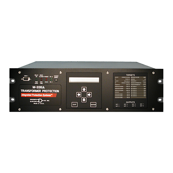
- Page 28 M‑3311A Transformer Protection Relay 5.65 [14.40] 5.59 6.19 0.03 [14.20] [15.7] [0.076] Actual 2.25 1.97 2.25 1.67 0.35 [5.72] [5.0] [5.72] [4.24] [0.89] 0.28 [0.71] Dia. (4X) TARGETS 19.00 [48.26] OUTPUTS OUT 1 OUT 3 OUT 5 OUT 7 18.30...
- Page 29 ( 3 A B ) P S 1 NOTES: 1. The M-3311A Expanded I/O vertical panel is the same physical size as the M-3311A Expanded I/O horizontal panel. See Figure 14 for dimensions. 2. See Instruction Book Chapter 5 for Mounting and Cutout information.
- Page 30 M‑3311A Transformer Protection Relay This Page Left Intentionally Blank –29–...
- Page 31 BECKWITH ELECTRIC CO., INC. 6190 - 118th Avenue North • Largo, Florida 33773-3724 U.S.A. PHONE (727) 544-2326 • FAX (727) 546-0121 marketing@beckwithelectric.com www.beckwithelectric.com ISO 9001:2008 © 2005 Beckwith Electric Co. 800-3311A-SP-08 09/15 Printed in U.S.A. (1.15.03)
- Page 32 WARNING DANGEROUS VOLTAGES, capable of causing death or serious injury, are present on the external terminals and inside the equip- ment. Use extreme caution and follow all safety rules when han- dling, testing or adjusting the equipment. However, these internal voltage levels are no greater than the voltages applied to the exter- nal terminals.
- Page 33 PRODUCT CAUTIONS Before attempting any test, calibration, or maintenance procedure, personnel must be completely familiar with the particular circuitry of this unit, and have an adequate understanding of field effect devices. If a component is found to be defective, always follow replacement procedures carefully to that assure safety features are maintained.
-
Page 34: Table Of Contents
Appendix D: Inverse Time Curves ............1-2 Appendix E: Layup and Storage ............1-2 Appendix F: HMI Menu Flow ..............1-2 M-3311A Transformer Protection Relay ..........1-2 Communication Ports ................1-3 S-3300 IPScom Communications Software .......... 1-3 Accessories ................... 1-4 M-3911A Target Module ................ - Page 35 M‑3311A Instruction Book Chapter 2 Operation (Cont.’d) Operation (HMI/PC) ................2-4 HMI Operation Overview ............... 2-4 Default Message Screens ..............2-4 HMI Security ..................2-4 Status Monitoring (From Relay Front Panel) ......... 2-6 Status Monitoring (From IPScom ) ............2-7 ®...
- Page 36 M‑3311A Instruction Book Chapter 3 IPScom ® IPScom Functional Description ............. 3-1 IPScom Main Screen Menu Bar ............3-1 Shortcut Command Buttons ..............3-1 IPScom Main Screen Status Line ............3-1 File Menu ....................3-4 File/New Command ................3-4 File/Save and Save As Command ............3-4 File/Open Command ................
- Page 37 M‑3311A Instruction Book Chapter 4 System Setup and Setpoints Unit Setup ..................... 4-1 General Unit Setup................4-1 Comm Access Code ................4-1 IPScom Comm Access Code Setup ............ 4-2 ® HMI Comm Access Code Setup ............4-2 IPScom User Access Code Setup ............4-3 HMI User Access Codes Setup ............
- Page 38 M‑3311A Instruction Book Chapter 4 System Setup and Setpoints (Cont’d.) System Setpoints ................4-49 Setpoint Profiles (Setting Groups) ............4-49 Configure Relay Data ................4-49 Functions .................... 4-49 Special Considerations ............... 4-50 24 Volts/Hz Overexcitation ..............4-51 27 Phase Undervoltage ..............4-55 4 Winding ....................
- Page 39 Phase Angle Shift - Standard Connections ........4-100 Phase Angle Shift - Custom Connections ........4-102 Calculation of Differential & Restraint Currents ......... 4-104 M-3311A Connection Examples ............4-104 Auxiliary Transformer Example (Three Windings) ......4-104 GSU Transformer Example ............... 4-104 Beckwith: Y/Delta-ac/Delta-ac ............
- Page 40 M‑3311A Instruction Book Chapter 6 Testing Equipment and Test Setup ..............6-2 Required Equipment ................6-2 Equipment Setup .................. 6-2 Diagnostic Test Procedures ..............6-3 Output Test (Relay) ................6-3 Input Test (Status) ................. 6-4 Status LED Test ..................6-5 Target LED Test ..................
- Page 41 M‑3311A Instruction Book Appendix A Configuration Record Forms System Communication Setup .............. A-4 Setup System – Two or Three Windings ..........A-5 Setup System – Four Windings ............. A-8 System Setpoints and Settings ............A-11 Appendix B Communications DNP Configuration Parameters ............. B-1 M-3311 Slave Address ................
- Page 42 Typical 4 Winding M-3911A Target Module........... 1-4 M-3931 Human-Machine Interface (HMI) Module ......... 1-4 Chapter 2 Operation M-3311A Front Panel ................... 2-3 Screen Message Menu Flow ................ 2-4 Main HMI Menu Flow ................... 2-5 Primary Metering & Status Screen (2/3 Winding) ......... 2-7 Primary Metering &...
- Page 43 M‑3311A Instruction Book Figures Page Chapter 3 IPScom (Cont’d.) ® IPScom Modem Communication Dialog Screen ........... 3-6 Terminal Window ..................3-6 Primary Metering Status Screen (2/3 Winding) ..........3-7 3-10 Primary Metering Status Screen (4 Winding) ..........3-8 3-12 Secondary Metering Status Screen (2/3 Winding)........3-9 3-12 Secondary Metering Status Screen (4 Winding) .........3-10...
- Page 44 IPScom Selection Screen for Output Settings ..........4-38 4-18 IPScom Selection Screen for Input Settings ..........4-39 4-19 M-3311A (Two Winding-Two or Four Voltage Inputs) Typical One-Line Function Diagram ............4-40 4-20 M-3311A (Three Winding-Two or Four Voltage Inputs) Typical One-Line Function Diagram ............4-41...
- Page 45 Installation M-3311A Horizontal Chassis Mounting Dimensions Without Expanded I/O (H1) ................5-2 M-3311A Mounting Dimensions – Horizontal Chassis With Expanded I/O (H5 and H6) ..............5-3 Panel Mount Cutout Dimensions ..............5-4 Vertical Chassis Mounting Dimensions Without Expanded I/O (H2) ..... 5-5 Mounting Dimensions for GE L-2 Cabinet (H3 and H4) .......
- Page 46 Typical (Three Winding – Four Voltage Inputs) Three-Line Connection Diagram..............5-32 5-33 Typical (Four Winding – Two Voltage Inputs) Three-Line Connection Diagram..............5-33 5-34 M-3311A Circuit Board Standard I/O ............5-38 5-35 M-3311A Circuit Board Expanded I/O ............5-39 5-36 IPScom Program Icon .................5-40 xiii...
- Page 47 Setup System (Four Windings) (page 1 of 3) ..........A-8 System Setpoints and Settings (page 1 of 38) ........... A-11 Appendix B Communication Null Modem Cable for M-3311A ..............B-3 RS-232 Fiber Optic Network ................ B-4 RS-485 Network ................... B-5 Appendix D Inverse Time Curves Volts/Hz (24IT) Inverse Curve Family #1 (Inverse Square) ......
- Page 48 Relay Communication Menu Flow (Page 1 of 2) ........F-22 F-14 Relay Setup Menu Flow (Page 1 of 4) ............F-24 Tables Page Chapter 1 Introduction M-3311A Device Functions ................1-2 Chapter 2 Operation 4 Winding Recorder Partitions ..............2-18 2/3 Winding Recorder Partitions ..............2-19 Chapter 3 IPScom ®...
- Page 49 M‑3311A Instruction Book Tables Page Chapter 4 System Setup and Setpoints (Cont’d.) 4‑5 Transformer Connections ................4‑97 4‑6 Standard Transformer and CT Configuration Options ........4‑98 4‑7 Custom Transformer and CT Configuration ..........4‑99 Chapter 5 Installation 5‑1 Circuit Board Jumpers .................5‑36 5‑2 Circuit Board Switches ................5‑36...
-
Page 50: Instruction Book Contents
It describes the procedures for entering Chapter 1: Introduction all required data into the M-3311A. Included in this Chapter One summarizes the devices’ capabilities, chapter are functional and connection diagrams for introduces the instruction book contents and a typical application for the system;... -
Page 51: Chapter 6: Testing
IEEE inverse time curves. The M-3931 Human Machine Interface (HMI) Module allows the user to access the following features and functions from the M-3311A front panel using a menu- Appendix E: Layup and Storage driven, 2 line by 24 character alphanumeric display:... -
Page 52: Communication Ports
Appendix B, Communications, as well as Chapter 3, IPScom ® The M-3311A retains up to 311 cycles of oscillograph waveform data assignable to up to 24 events with The system may be remotely set and interrogated selectable post-trigger delay. -
Page 53: S-3300 Ipscom Communications Software
M‑3311A Instruction Book S‑3300 IPScom Communications Software Accessories Each M-3311A unit includes the S-3300 IPScom Communications Software. The IPScom M‑3911A Target Module communications software runs on an IBM PC The optional target modules shown in Figures 1-1 compatible computer running under Windows 2000... -
Page 54: M-3933/M-0423 Serial Communication Cables
The M-0423 cable is a 10-foot null-modem RS-232 Protection Relay. cable for direct connection between a PC and the M-3311A front panel COM1 port, or the rear COM2 M‑3933/M‑0423 Serial Communications Cable port. This cable includes a DB9 (9-pin) connector at The M-3933 cable is a 10-foot straight-through each end. - Page 55 M‑3311A Instruction Book This Page Left Intentionally Blank 1–6...
-
Page 56: Chapter 2 Operation
Front Panel Controls and Indicators ........2–1 Operation (HMI/PC) ..............2–4 This chapter contains information that describes the • Oscillograph Recorder operation of the M-3311A Transformer Protection View Recorder Status Relay. See Chapter 4 for System Setup, Configuration Retrieve Records and Setpoint information. - Page 57 Any changed setpoint in the displayed screen will not be saved if This section describes the operation of the M-3311A the selection is aborted using the EXIT pushbutton. as a function of the M-3931 Human Machine Interface Module (HMI) and the M-3911A Target Module.
-
Page 58: Power Supply (Ps1) And (Ps2) Leds
Detailed information about the cause of the last 8 through the alphanumeric display from the VIEW operations is retained in the unit’s memory for access TARGET HISTORY menu. through the alphanumeric display from the VIEW TARGET HISTORY menu. Figure 2‑1 M‑3311A Front Panel 2–3... -
Page 59: Hmi Operation Overview
Whenever power is applied to the unit the Power On Self Test sequence is initiated (Figure 2-2). The purpose of this section is to describe the steps that are necessary to interrogate the M-3311A utilizing Default Message Screens either the optional M-3931 HMI or a PC running ®... - Page 60 Operation – 2 2–5...
-
Page 61: Status Monitoring (From Relay Front Panel)
M‑3311A Instruction Book Level 3 Access: provides access to all M-3311A To access the STATUS menu and begin monitoring, proceed as follows: configuration functions and settings. Press the ENTER pushbutton. Level 2 Access: provides access to read & change setpoints, monitor status and view target history. -
Page 62: Status Monitoring (From Ipscom)
Operation – 2 Status Monitoring (From IPScom) • Zero Sequence Current (W1 — W4) PRIMARY METERING AND STATUS • Differential Current (PU), (Phase A/B/C) To access the PRIMARY METERING AND STATUS • Restraint Current (PU), (Phase A/B/C) ® , select Monitor/Primary parameters utilizing IPScom •... -
Page 63: Primary Metering & Status Screen (4 Winding)
M‑3311A Instruction Book Path: Monitor / Primary Metering & Status Figure 2‑5 Primary Metering & Status Screen (4 Winding) 2–8... -
Page 64: Secondary Metering And Status
Operation – 2 SECONDARY METERING AND STATUS • Negative Sequence Current (W1 — W4) To access the SECONDARY METERING AND • Zero Sequence Current (W1 — W4) ® STATUS parameters utilizing IPScom , select • Differential Current (PU), (Phase A/B/C) Monitor/Secondary Metering and Status from the •... -
Page 65: Secondary Metering & Status Screen (4 Winding)
M‑3311A Instruction Book Path: Monitor / Secondary Metering & Status Figure 2‑7 Secondary Metering & Status Screen (4 Winding) 2–10... -
Page 66: Metering Ii
Operation – 2 METERING II Also included on the Metering II screen are: To access the METERING II parameters utilizing NOTE: These parameters are described in their ® , select Monitor/Metering II from the IPScom respective sections of this chapter. IPScom Main Screen drop down menu. - Page 67 M‑3311A Instruction Book Path: Monitor / Metering ll Figure 2‑9 Metering II Screen (4 Winding) 2–12...
-
Page 68: Demand Interval
Operation – 2 Demand Status If Level Access is not Active, then the following will be displayed: Monitored Primary Demand values include: VOLTAGE RELAY • Winding 1, 2, 3, & 4 Phase Currents VOLT curr freq v/hz • Winding 2, 3, and 4 Ground Current Press the Right arrow pushbutton until Maximum Demand Current the following is displayed:... -
Page 69: Demand Status Screen
M‑3311A Instruction Book If you are already in the DEMAND LEVEL #(1,2 or 3) STATUS menu, then go to Step 5. Access Granted! If Level Access is not Active, then the following will be displayed: VOLTAGE RELAY VOLTAGE RELAY VOLT curr freq... -
Page 70: Demand Status (From Ipscom)
Operation – 2 Demand Status (From IPScom) The Demand Status dialog screen also includes the capability to reset individual or reset all Max Demand Demand Currents Status values. To display Demand Currents select Monitor/ ® Metering II. IPScom will display the Metering II VIEW TARGET HISTORY screen (Figures 2-8 or 2-9). - Page 71 M‑3311A Instruction Book b. If the proper Access Code has been a. Input the required Access Code, then press ENTER. entered, the HMI will return: b. If the proper Access Code has been LEVEL #(1,2 or 3) entered, the HMI will return:...
-
Page 72: View Target History (From Ipscom)
Operation – 2 View Target History (From IPScom) The View Targets screen also includes the ability to Save the target information to file and Print the View Targets target information. To View Targets select Relay/Targets/View. ® IPScom will display the View Targets screen (Figure Clear Targets 2-11). -
Page 73: Oscillograph Recorder Data
M‑3311A Instruction Book ® Select Yes. IPScom • Post-Trigger Delay: A post-trigger delay will display the Clear Targets dialog screen (Figure 2-13). of 5% to 95% must be specified. After triggering, the recorder will continue to store data for the programmed portion of the total record before re-arming for the next record. -
Page 74: Winding Recorder Partitions
Operation – 2 Number of 3 Windings 2 Windings 3 Windings 2 Windings 3 Windings 2 Windings Partitions Windings 4 Voltages 2 Voltages 2 Voltages Zero Voltages Zero Voltages Table 2‑2 2/3 Winding Recorder Partitions 2–19... -
Page 75: Oscillograph Recorder (From Ipscom)
M‑3311A Instruction Book To access the Oscillograph Recorder VIEW To exit press the EXIT pushbutton. The RECORDER STATUS feature, proceed as follows: display will return to the following: VIEW RECORDER STATUS Press the ENTER pushbutton. STAT clear setup If Level Access is active, the following is... -
Page 76: Retrieve Oscillograph Records
Operation – 2 Press the ENTER pushbutton, the follow- ing will be displayed: CLEAR RECORDS -RECORDS CLEARED- To exit press the EXIT pushbutton. The display will return to the following: Figure 2‑15 Oscillograph Record Download VIEW RECORDER STATUS Dialog Screen stat CLEAR setup... -
Page 77: Trigger Oscillograph
M‑3311A Instruction Book Trigger Oscillograph Clear Oscillograph Records To manually Trigger the Oscillograph perform the To Clear Oscillograph Records perform the following: following: Select Relay/Oscillograph/Clear. Select Relay/Oscillograph/Trigger. I P S c o m w i l l d i s p l ay t h e C l e a r ®... -
Page 78: Software Version (Relay Front Panel Only)
Operation – 2 Software Version (Relay Front Panel only) Serial Number (Relay Front Panel only) To determine the software version installed on the To determine the serial number of the relay, proceed relay, proceed as follows: as follows: Press the ENTER pushbutton. Press the ENTER pushbutton. -
Page 79: Alter Access Codes (From Relay Front Panel)
M‑3311A Instruction Book Alter Access Codes (From Relay Front Panel) Input the desired User Access Code as follows: Press the ENTER pushbutton. a. Utilizing the Up and Down arrow If Level Access is active, the following is pushbuttons select the desired first displayed: digit. -
Page 80: Alter User Access Codes (From Ipscom)
Operation – 2 Alter User Access Codes (From IPScom) Comm Access Codes To set the relay Comm Access Code perform the following: NOTE: Communication must be established with the target relay for this procedure. ® From the IPScom Main Screen menu Figure 2-23 Access Code Changed Confirmation select Tools/Security/Change Comm Access Code. -
Page 81: System Error Codes, Output And Alarm Counters
M‑3311A Instruction Book User Access Codes System Error Codes, Output and Alarm Counters To change the relay User Access Codes perform The System Error Codes, Output and Alarm Coun- the following: ters feature provides the user with the ability to view and clear system Error Codes, Processor Resets, ... -
Page 82: Clear Output Counters (Relay Front Panel)
Operation – 2 Press ENTER, the following will be dis- Press the Right arrow pushbutton until the following is displayed: played: CLEAR OUTPUT COUNTER SOFTWARE VERSION logo1 logo2 OUT alrm VERS sn access number Press ENTER, the following will be dis- Press the Right arrow pushbutton until played: the following is displayed:... -
Page 83: Resetting Counters (From Ipscom)
M‑3311A Instruction Book Press the Right arrow pushbutton until Press ENTER, the following will be dis- the following is displayed: played: SETUP UNIT CLEAR ERROR CODES SETUP -ERROR CODES CLEARED- Press ENTER, the following will be dis- Press EXIT as necessary to return to the played: main menu. -
Page 84: Through Fault Recorder (From Ipscom)
Operation – 2 Through Fault Recorder (From IPScom) Relay/Through Fault/View Relay/Through Fault/Retrieve To view available Through Fault records perform the following: To download available Through Fault records perform the following: From the IPScom Main Screen menu select Relay/Through Fault/View. ® From the IPScom Main Screen menu IPScom will display the View Through... -
Page 85: Clear Through Fault Record Confirmation Screen
M‑3311A Instruction Book Relay/Through Fault/Clear Relay/Sequence of Events/Retrieve The Retrieve selection downloads the events from To Clear the relay Through Fault records perform the following: the currently connected relay (events must be retrieved from the relay and stored in a file in order ®... -
Page 86: View Sequence Of Events Record Screen
Operation – 2 Relay/Sequence of Events/View To Clear all Sequence of Events Records perform the following: The Sequence of Events viewer screen includes the commands Open, Close, Print Summary, and From the IPScom Main Screen menu Print. Open opens a saved sequence of events file. select Relay/Sequence of Events/Clear. - Page 87 M‑3311A Instruction Book This Page Left Intentionally Blank 2–32...
-
Page 88: Chapter 3 Ipscom
Connect and Help menu selections. This menu bar system settings and operational commands to includes the additional selections; Communication, the M‑3311A as well as access the extensive Monitor, System, Tools and Windows when monitoring and status reporting features. Figure IPScom is in either the file mode or has open 3‑3, represents the IPScom Main Screen menu... - Page 89 M‑3311A Instruction Book Figure 3-2 IPScom Main Screen 3–2...
-
Page 90: Ipscom Menu Selection
IPScom – 3 ® File Windows Cascade Unconnected Tile Vertical Monitor Help Connected Tile Horizontal Contents Primary Metering & Status Ctrl + F1 Open About... Secondary Metering & Status Save Open Metering II Save as Phasor Diagram Compare Phasor Diagram (87T) Close All Setpoints Pickup/Timeout Status... -
Page 91: File Menu
Closes the open file without saving. File/New Command File/Exit Command When not connected to a M‑3311A, using the New The Exit command quits the IPScom program. command, a new file is established with the New System dialog screen (Figure 3‑4). Selecting Save allows the new data file to be named by using the Save or Save as... -
Page 92: Connect\Communication Menu
IPScom – 3 ® Connect\Communication Menu Selecting “TCP/IP” displays the PC TCP/IP and device Settings (Figure 3‑6) for Ethernet communication. Selecting “Modem” displays a modem Dialog screen (Figure 3‑7), to establish contact with remote locations. The Modem Dialog screen also includes a “Bring up terminal window after dialing”... -
Page 93: Ipscom Modem Communication Dialog Screen
M‑3311A Instruction Book Figure 3-7 IPScom Modem Communication Dialog Screen Figure 3-8 Terminal Window 3–6... -
Page 94: Monitor Menu
IPScom – 3 ® Monitor Menu • Frequency (Hz) The Monitor Menu provides access to the screens • Volts Per Hertz (%) used to monitor relay parameters. Seven submenus • Current (W1 — W4) are provided: Primary Metering and Status, •... -
Page 95: Primary Metering Status Screen (4 Winding)
M‑3311A Instruction Book Path: Monitor / Primary Metering and Status Figure 3-10 Primary Metering Status Screen (4 Winding) 3–8... -
Page 96: Monitor/Secondary Metering & Status
IPScom – 3 ® Monitor/Secondary Metering & Status • Differential Current (PU), (Phase A/B/C) The Secondary Metering and Status screen • Restraint Current (PU), (Phase A/B/C) (Figures 3‑11 and 3‑12) allow the user to review • Ground Differential Current (W2 — W4) the following SECONDARY parameters: •... -
Page 97: Secondary Metering Status Screen (4 Winding)
M‑3311A Instruction Book Path: Monitor / Secondary Metering and Status Figure 3-12 Secondary Metering Status Screen (4 Winding) 3–10... -
Page 98: Monitor/Metering Ii
IPScom – 3 ® Monitor/Metering II • Demand Ground Currents, Winding 2, 3, & 4 The Metering II screen (Figures 3‑13 and 3‑14) include the following parameters: • Cumulative Through Currents (kA Cycles) • Through Fault Counter • 2 and 5 Harmonic Differential Currents (PU), (Phase A/B/C) Demand Status... -
Page 99: Metering Ii Screen (4 Winding)
M‑3311A Instruction Book Path: Monitor / Metering ll Figure 3-14 Metering II Screen (4 Winding) 3–12... -
Page 100: Monitor/Phasor Diagram
IPScom – 3 ® Monitor/Phasor Diagram The Phasor Diagram (Figures 3‑15 and 3‑16) provide the user with the ability to evaluate a reference Phase Angle to Phase Angle data from other windings. The Phasor Diagram also includes a menu that allows the user to select/deselect sources to be displayed and Freeze capability to freeze the data displayed on the Phasor Diagram. -
Page 101: Phasor Diagram (4 Winding)
M‑3311A Instruction Book Path: Monitor / Phasor Diagram NOTE: When connections specifying delta-connected CTs are used, Functions 87T and 87H use the Phasor Diagram values (currents actually entering the relay) and not the calculated values dis‑ played on the Secondary Metering and status screen. -
Page 102: Monitor/Phasor Diagram (F87T)
IPScom – 3 ® Monitor/Phasor Diagram (F87T) The Phasor Diagram (F87T) (Figures 3‑17 and 3‑18) provide the user with the ability to evaluate compensated and uncompensated 87 Function parameters. Path: Monitor / Phasor Diagram (F87T) Figure 3-17 Phasor Diagram (F87T) (2/3 Winding) 3–15... -
Page 103: Phasor Diagram (F87T) (4 Winding)
M‑3311A Instruction Book Path: Monitor / Phasor Diagram (F87T) Figure 3-18 Phasor Diagram (F87T) (4 Winding) 3–16... -
Page 104: Monitor/Pickup/Timeout Status
IPScom – 3 ® Monitor/Pickup/Timeout Status The Pickup/Timeout Status screen (Figures 3‑19 and 3‑20) display the extended status information of relay functions and Input/Output contact information. Path: Monitor / Pickup/Timeout Status Figure 3-19 Pickup/Timeout Status (2/3 Winding) Path: Monitor / Pickup/Timeout Status Figure 3-20 Pickup/Timeout Status (4 Winding) 3–17... -
Page 105: Monitor/87T Dual Slope
M‑3311A Instruction Book Monitor/87T Dual Slope The 87T Dual Slope display allows the user to display a graphical representation of the 87T programmable Dual Slope Percentage Restraint Characteristic. See Section 4.4, System Setpoints for detailed information. Path: Monitor / 87TDual Slope Figure 3-21 87T Function Dual Slope Display 3–18... -
Page 106: Relay Menu
IPScom – 3 ® Relay Menu Relay/Setup/Setup System The Setup System selection displays the Setup System dialog screen (Figures 3‑22 and 3‑23) allowing the user to input the pertinent information regarding the system on which the relay is applied (see Section 4.2, Setup System, for detailed information regarding the specific elements of the Setup System dialog screen). - Page 107 M‑3311A Instruction Book Figure 3-22 Setup System Dialog Screen (2/3 Winding) 3–20...
- Page 108 IPScom – 3 ® Figure 3-23 Setup System Dialog Screen (4 Winding) 3–21...
-
Page 109: Relay/Setup/Relay Setpoints
M‑3311A Instruction Book Relay/Setup/Relay Setpoints The Relay Setpoints menu selection displays the Relay Setpoints dialog screen (Figures 3‑24 and 3‑25) from which the individual Function Setting dialog screens can be accessed. Selecting a Function Setting button will display the corresponding function dialog screen (See Figure 3‑26 as an example). -
Page 110: Relay/Setup/Set Date & Time
IPScom – 3 ® Figure 3-26 Example Function Dialog Screen COMMAND BUTTONS Save When connected to a relay, sends the currently displayed information to the unit. Otherwise, saves the currently displayed information and returns to the System Setpoints screen or All Setpoints Table. Cancel Returns to the System Setpoints screen or All Setpoints Table;... -
Page 111: Relay/Setup/Display/I/O Map
M‑3311A Instruction Book Relay/Setup/Display/I/O Map Both the Relay Setpoints dialog screen and the I/O Map screen include the Display All Setpoints Selecting the I/O Map button displays the I/O feature and Jump Command Buttons which allow Map dialog screen (Figures 3‑28 and 3‑29), which... -
Page 112: O Map Screen (4 Winding)
IPScom – 3 ® Figure 3-29 I/O Map Screen (4 Winding) 3–25... -
Page 113: Relay/Setup/Display All Setpoints
M‑3311A Instruction Book Relay/Setup/Display All Setpoints The individual Feature and Function selection buttons are described in the applicable sections. Selecting the Display All Setpoints button displays the All Setpoints dialog screen (Figures 3‑30 and The All Setpoint Table includes Jump Command 3‑31). -
Page 114: Display All Setpoints Screen (4 Winding)
IPScom – 3 ® Figure 3-31 Display All Setpoints Screen (4 Winding) 3–27... -
Page 115: Relay/Demand Status
M‑3311A Instruction Book Relay/Demand Status The Demand Status feature allows the user to access Primary Demand Values. See Chapter 2, Operation for detailed information. Figure 3-32 Demand Status Dialog Screen (2/3 Winding) Figure 3-33 Demand Status Dialog Screen (4 Winding) -
Page 116: Relay/Targets
IPScom – 3 ® Relay/Targets The Targets submenu provides three command options: View, Clear and Reset LED. The View command displays the View Targets Dialog Screen (see Figure 3‑34). This dialog screen provides detailed data on target events including time, date, function status, phase current values, and IN/ OUT contact status at the time of trip. -
Page 117: Relay/Through Fault
M‑3311A Instruction Book Relay/Through Fault The Through Fault submenu provides three command options: Retrieve, View and Clear. The Retrieve command initiates the retrieval of any Through Faults present in the relay. The View command displays the View Through Fault Record dialog screen (Figure 3‑35). -
Page 118: Relay/Sequence Of Events
IPScom – 3 ® Relay/Sequence of Events The Sequence of Events submenu allows the user to Setup, Retrieve, View and Clear Sequence of Events records. The Setup command displays the Setup Sequence of Events Recorder dialog screen (Figure 3‑36). Function Pickup, Trip and Dropout can be selected to initiate the recorder as well as Input Pickup, Output Pickup, Inputs Drop and Outputs Drop. -
Page 119: View Sequence Of Events Recorder Screen
M‑3311A Instruction Book Figure 3-38 View Sequence of Events Recorder Screen 3–32... -
Page 120: Relay/Oscillograph
IPScom – 3 ® Relay/Oscillograph The Oscillograph submenu allows setting and control over the relay’s oscillograph recorder. The Setup command allows the user to set the number of partitions and triggering designations to be made (Figure 3‑39 and 3‑40), Retrieve downloads and save data to a file (Figure 3‑41). -
Page 121: Relay/Profile
M‑3311A Instruction Book Relay/Profile The Profile submenu provides three command options: Switching Method, Select Profile, and Copy Active Profile. The Switching Method command allows selection of either Manual or Input contact (Figure 3‑42). Select Profile allows the user to designate the active profile (Figure 3‑43). -
Page 122: Relay/Write File To Relay
IPScom – 3 ® Relay/Write File to Relay Tools/Security The Security menu item includes the Change Comm Access and Change User Access code submenus. Tools/Security/ Change Comm Access Code The Change Comm Access code selection displays the Change Comm Access Code screen (Figure 3‑45) which allows the user to change the Comm Access Code. -
Page 123: Tools/Security/Change User Access Code
M‑3311A Instruction Book Tools/Security/Change User Access Code The Change User Access Code selection displays the Access Level Code dialog screen (Figure 3‑46). After entering a valid Level 3 Access Code IPScom ® will display Figure 3‑47 which allows the user to change the relay User Access Code. -
Page 124: User Control Number
IPScom – 3 ® User Control Number The User Control Number is a user‑defined value which can be used for inventory or identification. The unit does not use this value, but it can be accessed through the HMI or the communications interface, and can be read remotely. -
Page 125: Output Test Warning Dialog Screen
M‑3311A Instruction Book Figure 3-52 Output Test Warning Dialog Screen Figure 3-53 Output Test Dialog Screen Figure 3-54 Counters and Error Codes Dialog Screen 3–38... -
Page 126: Tools/Firmware Update
Tools/Calibration Data The Calibration Data feature allows the user to The Help menu provides two commands. The retrieve calibration data from M‑3311A relays. It Contents command initiates a link to a PDF also allows relay calibration data to be restored to (Portable Document File) version of this instruction the relay. - Page 127 M‑3311A Instruction Book This Page Left Intentionally Blank 3–40...
-
Page 128: 4.1 Unit Setup
If additional link security is desired, a communica- tion access code can be programmed. Like the user The selection of the M-3311A System Setup param- access codes, if the communication access code eters and Setpoints can be performed using either... -
Page 129: Ipscom Comm Access Code Setup
M‑3311A Instruction Book IPScom Comm Access Code Setup To set the relay Comm Access Code perform the following: NOTE: Communication must be established with the target relay for this procedure. From the IPScom Main Screen menu Figure 4-3 Access Code Changed Confirmation select Tools/Security/Change Comm Access Code. -
Page 130: Ipscom User Access Code Setup
System Setup and Setpoints – 4 Press ENTER, the following will be dis- Each access code is a user-defined one-to-four played: digit number. Access codes can only be altered by a Level 3 user. COM1 SETUP COM1 com2 com3 com_adr If the Level 3 Access Code is set to 9999, the access code feature is disabled. -
Page 131: Hmi User Access Codes Setup
M‑3311A Instruction Book HMI User Access Codes Setup Input the desired User Access Code as follows: Press the ENTER pushbutton. Utilizing the Up and Down arrow push- If Level Access is active, the following is buttons select the desired first digit. -
Page 132: User Logo Line
System Setup and Setpoints – 4 USER LOGO LINE HMI User Logo Line Setup Press the ENTER pushbutton. The user logo is a programmable, two-line by 24-char- acter string, which can be used to identify the relay, If Level Access is active, the following is and which is displayed locally when the unit is idle. -
Page 133: Hmi User Control Number Setup
M‑3311A Instruction Book Input the desired User Logo Line 1 as HMI User Control Number Setup follows: Press the ENTER pushbutton. Utilizing the Up and Down arrow push- If Level Access is active, the following is buttons select the desired first letter/ displayed: symbol/digit/blank space. -
Page 134: Hmi System Ok Led Setup
System Setup and Setpoints – 4 Input the desired User Control Number ▲ CAUTION: Do not enter DIAGNOSTIC MODE as follows: when protected equipment is in service. Entering DI- AGNOSTIC MODE when protected equipment is in Utilizing the Up and Down arrow push- service removes all protective functions of the relay. -
Page 135: System Clock
M‑3311A Instruction Book Utilizing the Right or Left arrow pushbut- IPScom Set Date/Time tons select either ON or OFF. To set the relay Date/Time perform the following: NOTE: Communication must be established with Press ENTER, the following will be dis- the target relay for this procedure. - Page 136 System Setup and Setpoints – 4 Press the RIGHT arrow pushbutton until Press the Left arrow pushbutton once, the following is displayed: then repeat the previous step as neces- sary to input the desired date. SETUP UNIT When the desired Date has been input, stat comm SETUP then press ENTER.
-
Page 137: Communication Setup
IPScom will display the Setup Comm COM3 located on the rear terminal block of the Port dialog screen (Figure 4-7). M-3311A is an RS-485, 2-wire connection. Appendix The System COM Port that is in use will B, Figure B-3 illustrates a 2-wire RS-485 network. -
Page 138: Setup Comm Port Dialog Screen
System Setup and Setpoints – 4 Select the desired COM Port to be setup The individual addressing capability of (1, 2 or 3). IPScom and the relay allows multiple systems to share a direct or modem con- Enter the desired “Baud Rate” (1200 nection when connected through COM2 to 9600). -
Page 139: Hmi Com Port Definitions And Device Address
M‑3311A Instruction Book HMI COM Port Definitions and Device Address Input the desired Dead Sync Time as follows: Press the ENTER pushbutton. Utilizing the Up and Down arrow push- If Level Access is active, the following is buttons select the desired first digit. -
Page 140: Ethernet Communication Settings
System Setup and Setpoints – 4 ETHERNET COMMUNICATION SETTINGS IPScom Ethernet Port Setup with DHCP NOTE: Communication must be established with The optional RJ45 Ethernet port can be enabled the target relay for this procedure. utilizing either IPScom from the Ethernet Settings ®... -
Page 141: Ipscom Ethernet Port Setup Without Dhcp
M‑3311A Instruction Book IPScom Ethernet Port Setup without DHCP Ensure that TCP is selected (Upper ® Case). NOTE: Communication must be established with the target relay for this procedure. If TCP is not selected (Upper Case), then use the Right/Left arrow pushbuttons to From the IPScom Main Screen menu select TCP. -
Page 142: Manual Configuration Of Ethernet Board
System Setup and Setpoints – 4 If the ethernet board successfully obtains Enter the desired Gateway, then press ENTER, the following will be displayed: an IP Address the following will be dis- played for approximately 2 seconds: TCP/IP SETTINGS ETHERNET IP ADDRESS tcp prot XX.XX.XX.XX Ensure that PROT is selected (Upper... -
Page 143: Installing The Modems
M‑3311A Instruction Book INSTALLING THE MODEMS Connecting the PC Modem If the computer has an external modem, Using IPScom to interrogate, set or monitor the ® then use a standard straight-through relay using a modem requires both a remote modem... -
Page 144: Connecting The Local Modem To The Relay
System Setup and Setpoints – 4 IPScom will display the Modem Dialog NOTE: The relay does not issue or understand screen (Figure 4-10). any modem commands. It will not adjust the baud rate and should be considered Enter the required information in the a “dumb”... -
Page 145: Oscillograph Setup
M‑3311A Instruction Book OSCILLOGRAPH SETUP Number of Windings Windings Windings Partitions 1, 2, 3, 4 1, 2, 3 1, 2 The Oscillograph Recorder provides comprehen- sive data recording (voltage, current, and status input/output signals) for all monitored waveforms (at 16 samples per cycle). Oscillograph data can... -
Page 146: Winding Recorder Partitions
System Setup and Setpoints – 4 Number of 3 Windings 2 Windings 3 Windings 2 Windings 3 Windings 2 Windings Partitions Windings 4 Voltages 2 Voltages 2 Voltages Zero Voltages Zero Voltages Table 4-3 2/3 Winding Recorder Partitions 4–19... -
Page 147: Ipscom Setup Oscillograph Recorder
M‑3311A Instruction Book IPScom Setup Oscillograph Recorder Select the desired Trigger Inputs and Trigger Outputs. NOTE: Communication must be established with the target relay for this procedure. When The recorder can be triggered remotely not connected to the relay the Save se-... -
Page 148: Hmi Setup Oscillograph Recorder
System Setup and Setpoints – 4 HMI Setup Oscillograph Recorder Press ENTER, the following will be dis- played: Press the ENTER pushbutton. RECORDER PARTITIONS If Level Access is active, the following is displayed: ENTER ACCESS CODE Input the desired number of Recorder Partitions. -
Page 149: Ipscom Setup Sequence Of Events Recorder
M‑3311A Instruction Book IPScom Setup Sequence of Events Recorder Input the required Access Code, then press ENTER. Protective function Pickup, Trip, Dropout and/or Out- put/Input Pickup or Dropout are selected to trigger If the proper Access Code has been the Sequence of Events Recorder. -
Page 150: Setup Sequence Of Events Recorder Dialog Screen
System Setup and Setpoints – 4 Figure 4-14 Setup Sequence of Events Recorder Dialog Screen 4–23... -
Page 151: Hmi Demand Interval Setup
M‑3311A Instruction Book Press the ENTER pushbutton, the fol- Utilizing the Right or Left arrow pushbut- ton select the target winding, then press lowing will be displayed: ENTER, the following is displayed: VOLTAGE RELAY THFLT DELAY VOLT curr freq v/hz... -
Page 152: Setup System
System Setup and Setpoints – 4 Setup System NOTE: Table 4-4 assumes ACTIVE INPUT The Setup System consists of defining common STATE set to default setting (close circuit information like CT and VT ratios, nominal voltage = TRUE). rating, transformer connections, and which profile is the Active Profile, etc. -
Page 153: 2/3 Winding Setup (Cont.'d)
M‑3311A Instruction Book 2/3 Winding Setup (Cont.’d) ▲ CAUTION: Changing from a standard Transformer/CT XFM/CT CONNECTION connection to the equivalent custom setting may cause the standard custom relay to momentarily trip when current is present. If Custom XFM/CT Connection is DISABLED (standard... - Page 154 System Setup and Setpoints – 4 2/3 Winding Setup (Cont.’d) ▲ CAUTION: Changing from a standard Transformer/CT CT CONNECTION W1 connection to the equivalent custom setting may cause the CON_W1 xfm_w1 con_w2 xfm_w2 relay to momentarily trip when current is present. CT CONNECTION W1 ...
- Page 155 M‑3311A Instruction Book 2/3 Winding Setup (Cont.’d) PHASE ROTATION Indicates the phase rotation. PHASE seal in vt PHASE ROTATION a-c-b A-B-C Seal-in time for output relays. Eight individual seal-in delays RELAY SEAL-IN TIME can be specified for each output relay (OUT1-OUT16 for ...
- Page 156 System Setup and Setpoints – 4 2/3 Winding Setup (Cont.’d) VT Phase Ratio V.T.Phase RATIO VTP vtg volt curr V.T.Phase RATIO _________________ :1 V.T.Gnd/Phase RATIO VT Ground/Phase Ratio vtp VTG volt curr V.T.Gnd/Phase RATIO _________________ :1 The secondary VT voltage when primary voltage is equal NOMINAL VOLTAGE to the rated transformer voltage (V trans rated/VT ratio).
- Page 157 M‑3311A Instruction Book 2/3 Winding Setup (Cont.’d) CT Ground Ratios W2 C.T. GROUND RATIO ct_w1 ct_w2 CT_W2G The relay will calculate the W2 and W3 line currents when a delta CT configuration is selected, as follows: W2 C.T. GROUND RATIO...
-
Page 158: Winding Summing
System Setup and Setpoints – 4 4 Winding Setup If INPUT ACTIVATED PROFILES is disabled this screen INPUT ACTIVATED PROFILES allows manual selection of the Active Profile using the disable ENABLE front panel or through communications. ACTIVE SETPOINT PROFILE Allows the user to manually select the Active Profile. This screen initiates a copy of the Active Profile to any COPY ACTIVE PROFILE one of the other profiles. - Page 159 M‑3311A Instruction Book 4 Winding Setup (Cont.’d) ▲ CAUTION: Changing from a standard Transformer/CT CUSTOM XFM/CT CONNECTION connection to the equivalent custom setting may cause the disable enable relay to momentarily trip when current is present. If Custom XFM/CT Connection is DISABLED (standard...
- Page 160 System Setup and Setpoints – 4 4 Winding Setup (Cont.’d) ▲ CAUTION: Changing from a standard Transformer/CT CT CONNECTION W1 connection to the equivalent custom setting may cause the C O N _ W 1 xfm_w1 con_w2 xfm_w2 relay to momentarily trip when current is present.
- Page 161 M‑3311A Instruction Book 4 Winding Setup (Cont.’d) PHASE ROTATION Indicates the phase rotation. PHASE seal in vt PHASE ROTATION a-c-b A-B-C Seal-in time for output relays. Eight individual seal-in RELAY SEAL-IN TIME delays can be specified for each output relay (OUT1- ...
- Page 162 System Setup and Setpoints – 4 4 Winding Setup (Cont.’d) VT Ratio V.T.x RATIO VTX vtg ct_w1 ct_w2 V.T.x RATIO _________________ :1 V.T.g RATIO VT Ground Ratio vtx VTG ct_w1 ct_w2 V.T.g RATIO _________________ :1 CT Ratios W1 C.T. RATIO vtx vtg CT_W1 ct_w2...
-
Page 163: Ipscom ® Relay Setup System Dialog Screen (2/3 Winding)
M‑3311A Instruction Book Figure 4-15 IPScom Relay Setup System Dialog Screen (2/3 Winding) ® 4–36... -
Page 164: Ipscom Relay Setup System Dialog Screen (4 Winding)
System Setup and Setpoints – 4 Figure 4-16 IPScom Relay Setup System Dialog Screen (4 Winding) ® 4–37... -
Page 165: Ipscom Selection Screen For Output Settings
M‑3311A Instruction Book If neither Pulsed or Latched Output is enabled, the output contact will default to the normal mode. In this mode, the output contact will stay energized as long as the abnormal condition which caused it to operate persists. After the abnormal condition is cleared, the contact will reset after the programmed seal-in time has elapsed. -
Page 166: Ipscom Selection Screen For Input Settings
System Setup and Setpoints – 4 Figure 4-18 IPScom Selection Screen for Input Settings 4–39... -
Page 167: System Diagrams
Winding 2 Events (W2) Waveform Capture IRIG-B Front RS232 Communication Rear RS-232/485 Communication Multiple Setting Groups Programmable I/O Programmable Logic Self Diagnostics Dual Power Supply (Optional) Figure 4-19 M-3311A (Two Winding-Two or Four Voltage Inputs) Typical One-Line Function Diagram 4–40... - Page 168 Note: All 50 and 50G functions may be applied instantaneous or definite time, and are multiple (2) ele- ments, each with individual pickup and time delay setpoints. Figure 4‑20 M‑3311A (Three Winding‑Two or Four Voltage Inputs) Typical One‑Line Function Diagram...
-
Page 169: 3311A (Four Winding-Two Voltage Inputs Typical One-Line Function Diagram
All 50 and 50G functions may be applied instantaneous or definite time, and are multiple (2) elements, each with individual pickup and time delay setpoints. Two voltage inputs are available in the 4-winding model of the M-3311A. These are a phase voltage V... - Page 170 All 50 and 50G functions may be applied instantaneous or definite time, and are multiple (2) elements, each with individual pickup and time delay setpoints. Two voltage inputs are available in the 4-winding model of the M-3311A. These are a phase voltage V...
-
Page 171: Typical (Two Winding-Two Voltage Inputs) Three-Line Connection Diagram
M‑3311A Instruction Book M-3311A Output Contacts M-3311A (W-1) Self- OUT 2 OUT 1 Typical Typical Test Self- Power OK Trip Test Status Alarm Alarm Alarm Trip M-3311A Input Contacts IN 1 IN 2 IN 3 Winding 1 (52b) Typical Typical... -
Page 172: Typical (Two Winding-Four Voltage Inputs) Three-Line Connection Diagram
OUT 1 Typical Typical Test M-3311A (W-1) Self- Power OK Trip Test Status Alarm Alarm Alarm Trip M-3311A Input Contac ts IN 1 IN 2 IN 3 (52b) Typical Typical Return Other Other Inputs Inputs Winding 1 (W-1) Two VT Open-Delta Connections... -
Page 173: Typical (Three Winding-Two Voltage Inputs) Three-Line Connection Diagram
M‑3311A Instruction Book M-3311A Output Contacts Self- OUT 2 OUT 1 Test Typical Typical M-3311A (W-1) Self- Power OK Trip Test Status Alarm Alarm Alarm Trip M-3311A Input Contacts IN 1 IN 2 IN 3 (52b) Typical Typical Return Other... -
Page 174: Typical (Three Winding-Four Voltage Inputs) Three-Line Connection Diagram
Alternate VT connections (see Instruction Book Chapter 5) Status Inputs and Relay Output are designated. Extra Outputs ma y be designated for control/supervisory operation. M-3311A Two VT Open-Delta Connections M-3311A Input Contac ts IN 1 IN 2 IN 3 (52b) Typical Typical Return... -
Page 175: Typical (Four Winding-Two Voltage Inputs) Three-Line Connection Diagram
M‑3311A Instruction Book M-3311A (W-4) M-3311A (W-1) M-3311A Output Contacts M-3311A Input Contacts IN 1 IN 2 IN 3 (52b) Typical Typical Return Self- OUT 2 OUT 1 Typical Typical Test Other Other Inputs Inputs Self- Power OK Trip Test... -
Page 176: System Setpoints
System Setup and Setpoints – 4 Configure Relay Data System Setpoints The relay is shipped with a certain group of standard functions, including other optional functions, as Setpoint Profiles (Setting Groups) purchased. Both of these groups define a configurable Up to four setpoint profiles may be used. Each set of functions. -
Page 177: Special Considerations
M‑3311A Instruction Book Special Considerations The following functions can be configured using enable/disable output, and status input blocking Status input IN1 is pre-assigned to be the 52b designations: breaker contact. IN5 and IN6 may be used to se- lect setpoint profiles (with input activated profiles + 24 Volts/Hz Overexcitation: Definite Time enabled). -
Page 178: 24 Volts/Hz Overexcitation
NOTE: Two or four voltage inputs are available • Full Load V/Hz = 1.05 PU (HV terminals) for the M-3311A. The Voltage Input can • No Load V/Hz = 1.10 PU (HV terminals) be a phase voltage input or voltage generated from a broken delta VT con- nection. -
Page 179: Example Of V/Hz Capability And Protection Curves
M‑3311A Instruction Book 1000 Generator Limit Curve Transformer Limit Curve on Generator Base Inverse Square Curve K = 5 Combined Protection Curve Definite Time Delay Definite Time Pickup Inverse Time Pickup 0.01 Percentage Volts/Hz Figure 4-28 Example of V/Hz Capability and Protection Curves... - Page 180 System Setup and Setpoints – 4 24DT#1 PICKUP Definite time setpoint #1 establishes the V/Hz level above which 110% the protection operating time will be fixed at the definite time delay #1 (See Figure 4-28). 100% is equal to nominal voltage at nominal frequency (50/60Hz).
-
Page 181: Ipscom (24) Volts/Hertz Setpoint Ranges
M‑3311A Instruction Book Figure 4-29 IPScom (24) Volts/Hertz Setpoint Ranges ® Path: Relay/Setup/Relay Setpoints/24 Volts/HZ Overexcitation COMMAND BUTTONS Save Saves all information to the relay. Cancel Returns the user to the previous window; any changes to the displayed information are lost. -
Page 182: 27 Phase Undervoltage
The 27 Undervoltage function may be used to detect any condition causing long term undervoltage NOTE: Two or four voltage inputs are available for the M-3311A. The Voltage Input can This function is used to shed the transformer load be a phase voltage input or voltage... -
Page 183: Ipscom (27) Undervoltage Setpoint Ranges (4 Winding)
M‑3311A Instruction Book NOTE: Elements #2 and #3 are not available in Four Winding applications. Figure 4-30 IPScom (27) Undervoltage Setpoint Ranges (2/3 Winding) ® Figure 4-31 IPScom (27) Undervoltage Setpoint Ranges (4 Winding) Path: Relay/Setup/Relay Setpoints/27 Phase Undervoltage... -
Page 184: 46 Negative Sequence Overcurrent
System Setup and Setpoints – 4 46 Negative Sequence Overcurrent The inverse time function can be selected as one of the eleven curve families: definite, inverse, very The 46 Negative Sequence Overcurrent function inverse, extremely inverse, and four IEC curves and provides protection against possible damage due three IEEE curves. - Page 185 M‑3311A Instruction Book NOTE: Winding Four is not available in Two or Three Winding applications. Figure 4-32 IPScom (46) Negative Sequence Overcurrent Setpoint Ranges ® Path: Relay/Setup/Relay Setpoints/46 Negative Sequence Overcurrent COMMAND BUTTONS Save Saves all information to the relay.
-
Page 186: 49 Winding Thermal Protection
The M-3311A includes four setpoint groups that can accommodate a power transformer’s different MVA requirements. One setpoint group can be used... -
Page 187: Function Overload Curves
M‑3311A Instruction Book 49 - Overload Curves P=0.0 P=0.5 0.01 P=0.6 P=0.7 P=0.8 P=0.9 P=0.99 0.001 load preload where: P= Figure 4-33 49 Function Overload Curves 4–60... - Page 188 System Setup and Setpoints – 4 49 TIME CONSTANT Selects the time constant, ‘τ’ 5.0 Min 49 MAX OVERLOAD CURRENT Selects the maximum allowed continuous overload current. 2.00 Amps Select the winding current to be used as the input. 49 CURRENT SELECTION sum1 sum2 w1 w2 w3 w4 ...
-
Page 189: 50Bf Breaker Failure
50BF‑Residual Element 50BF‑Phase Breaker Failure This overcurrent relay is energized from the residual When the M-3311A Transformer Protection Relay current, see Figures 4-19 through 4-22, One-Line detects an internal transformer fault or an abnormal Functional Diagrams. This function is internally... - Page 190 System Setup and Setpoints – 4 50BFW1 PICKUP RESIDUAL Sets 50BFW1 residual current pickup. 0.5A is a typical setting. 1.00 Amps This element operates on 3I Sets 50BFW1 phase current pickup. 0.3 A is a typical setting. 50BFW1 PICKUP PHASE 1.00 Amps Designates the control/status inputs which will initiate the breaker 50BFW1 INPUT INITIATE...
-
Page 191: 50/50G Instantaneous Overcurrent, Phase & Ground
M‑3311A Instruction Book 50/50G Instantaneous Overcurrent, Phase & Ground NOTE: 50 Phase Instantaneous Overcurrent The Instantaneous phase 50 and Instantaneous Elements #7 and #8 are not available in Ground 50G overcurrent functions provide fast Two or Three Winding applications. -
Page 192: Ipscom (50G) Instantaneous Ground Overcurrent Setpoint Ranges
System Setup and Setpoints – 4 NOTE: Elements #7 and #8 are not available in Two or Three Winding applications. Figure 4-37 IPScom (50) Instantaneous Phase Overcurrent Setpoint Ranges ® Path: Relay/Setup/Relay Setpoints/50 Instantaneous Phase Overcurrent COMMAND BUTTONS Save Saves all information to the relay. -
Page 193: Instantaneous Residual Overcurrent
M‑3311A Instruction Book 50N Instantaneous Residual Overcurrent The Instantaneous Residual (50N) overcurrent function provides fast tripping for high fault currents. Settings must be made in such a way as to prevent pickup for fault or conditions outside the immediate protective zone. -
Page 194: 51 Inverse Time Phase Overcurrent
System Setup and Setpoints – 4 51 Inverse Time Phase Overcurrent dial within each family setting and tap setting is selected through the relay menu. The 51 Inverse Time Phase Overcurrent func- tion, one set per winding are used to trip circuits The curves available for use are shown in Appendix selectively and to time coordinate with up or down D, Inverse Time Curves, Figures D-5 through D-15. -
Page 195: 51N Inverse Time Residual Overcurrent
M‑3311A Instruction Book 51N Inverse Time Residual Overcurrent The curves available for use are shown in Appendix D, Inverse Time Curves, Figures D-5 through D-15. The 51 Inverse Time Residual Overcurrent provides They cover a range from 1.5 to 20 times tap. For protection against ground faults. -
Page 196: 51G Inverse Time Ground Overcurrent
System Setup and Setpoints – 4 51G Inverse Time Ground Overcurrent The curves available for use are shown in Appendix D, Inverse Time Curves, Figures D-5 through D-15. The 51G Inverse Time Ground Overcurrent func- They cover a range from 1.5 to 20 times the tap. tion is used to trip circuits selectively and to time For currents beyond 20 times the pickup setting, coordinate with up or downstream relays. -
Page 197: Phase Overvoltage (2/3 Winding)
M‑3311A Instruction Book 59 Phase Overvoltage (2/3 Winding) The relay provides overvoltage protection func- tions with three voltage levels and three definite- The 59 Phase Overvoltage function may be used to time setpoints, any one or more of which can be provide overvoltage protection for the transformer. -
Page 198: Winding
VT. If voltage input NOTE: Two or Four voltage inputs are available is connected to broken delta VT, Functions 81O/U, for the M-3311A. The voltage input can 27, and 24 will be unavailable. be a phase voltage input or voltage... - Page 199 . Basically 59G becomes 59N. When V is selected, the operating quantity is the measured voltage at the terminals of the M‑3311A relay. NOTE: This setting is only functional with firmware version V02.03.01 and later. Figure 4‑45 IPScom (59G) Ground Overvoltage Setpoint Ranges (2/3 Winding) ®...
-
Page 200: 81O/U Over/Underfrequency
The NOTE: Two or Four voltage inputs are available Underfrequency function is typically used for load for the M-3311A. The Voltage Input can shedding applications. The frequency functions are be a phase voltage input or voltage... - Page 201 M‑3311A Instruction Book Figure 4-46 IPScom (81O/U) Over/Underfrequency Setpoint Ranges ® Path: Relay/Setup/Relay Setpoints/81 Over/Under Frequency COMMAND BUTTONS Save Saves all information to the relay. Cancel Returns the user to the previous window; any changes to the displayed information are lost.
-
Page 202: 87 Phase Differential
System Setup and Setpoints – 4 87 Phase Differential 87H Phase Differential Unrestrained High Set Overcurrent The 87H Phase Differential Unrestrained High Set Overcurrent function is used to detect transformer internal winding faults with high currents. Unlike the 87T function, the 87H function is not blocked by harmonic restraint. -
Page 203: Ipscom (C.t. Tap) Phase Differential Current Setpoint Ranges
M‑3311A Instruction Book Figure 4-48 IPScom (87H) Phase Differential Current Setpoint Ranges ® Path: Relay/Setup/Relay Setpoints/87 Phase Differential Current COMMAND BUTTONS Save Saves all information to the relay. Cancel Returns the user to the previous window; any changes to the displayed information are lost. -
Page 204: Phase Differential
The over-excitation condition is detected by the inrush current is distinguishable from fault current by presence of Fifth Harmonic component as a per- harmonic components. The M-3311A Transformer centage of fundamental component of differential Protection Relay can be set to restrain if the level current above a set value. -
Page 205: Programmable Dual Slope Percentage Restraint Characteristic
M‑3311A Instruction Book F87T Dual Slope Slope 2 Differential Current (PU) Trip Restrain Minimum Pickup at Harmonic Restraint Slope 1 Break Break Point Point Minimum Pickup Restraint Current (PU) where = Σ a I a f + a f I... -
Page 206: Cross Phase Averaging
System Setup and Setpoints – 4 Cross Phase Averaging 87T CT Tap Settings For W1, W2, W3 and W4 Cross phase averaging is used to average the MVA x 10 harmonics of all three phases to provide restraint 87 CT Tap S3 x kVL-L x CTR of phases which may not have enough harmonics. - Page 207 M‑3311A Instruction Book See previous pages for more information on these settings. 87T PICKUP 87T EVEN RESTRAINT 0.50 PU 87T SLOPE #1 87T 5TH RESTRAINT disable enable CROSS_AVG 87T SLOPE #2 87T 5TH RESTRAINT 87T SLOPE BREAKPOINT 87T PICKUP@5TH RESTRAINT 2.0 PU...
-
Page 208: 87Gd Ground Differential
System Setup and Setpoints – 4 87GD Ground Differential The directional element is inoperative if the residual current (3I ) is approximately less than 140 mA NOTE: This function is not provided on Winding (approx., based on 5 A CT rating). For this case, One. - Page 209 M‑3311A Instruction Book NOTE: Winding Four is not available for Two or Three Winding applications. Figure 4-52 IPScom (87GD) Ground Differential Current Setpoint Ranges ® Path: Relay/Setup/Relay Setpoints/87GD Ground Differential current COMMAND BUTTONS Save Saves all information to the relay.
- Page 210 When the Output Contact is closed, no current flows for other available trip circuit input voltage selections. in the Trip Circuit Monitoring Input. If the M-3311A has issued a trip command to close the Output This function should be programmed to block when...
- Page 211 This selection allows the TCM #1 to be disabled (or enabled) independent When the Output Contact is closed, no current flows in the Trip Circuit Monitoring Input. If the M-3311A from the TCM #2. closes the Output Contact and Trip Circuit Monitor-...
-
Page 212: Tcm (Trip Circuit Monitoring)
Save/Cancel — The Save selection saves the the TCM function output. Function Dialog Screen settings either to an open file or to the target M-3311A. Cancel, returns the Dropout Time Delay — A Time Delay can be ap- user to the previous open screen. -
Page 213: Ccm (Close Circuit Monitoring)
“Y” coil will not drop When the M-3311A is not connected to the close out. Therefore, only one CCM, either a M-3311A or coil circuit, then the appropriate CCM alarm LED on... -
Page 214: Recommended Close Circuit Monitoring Input Configuration
System Setup and Setpoints – 4 M-3311A Close Circuit Monitoring Input Station Battery Output Other Contact Contacts Legend Anti-pump relay prevents reclosing on a sustained close command. A spring charge limit switch shown with breaker closing spring discharged. Close Coil Latch check switch, closed when latch is reset. -
Page 215: Close Circuit Monitoring Input Configuration With Anti-Pump Relay Not Bypassed
M‑3311A Instruction Book Figure 4-58 Close Circuit Monitoring Input Configuration with Anti-pump Relay Not Bypassed 4–88... -
Page 216: Breaker Monitoring
System Setup and Setpoints – 4 Breaker Monitoring contact. The accumulated value for each phase can be displayed as an actual value. The integration The Breaker Monitoring feature calculates an esti- starts after a set time delay from the initiate point mate of the per-phase wear on the breaker contacts to account for the time it takes for the breaker to by measuring and integrating the current or current... -
Page 217: Through Fault
M‑3311A Instruction Book Through Fault predict transformer failures facilitating corrective action. Recording the number and severity of The Through Fault Monitor feature of the relay Through Faults experienced by a transformer can provides the user with the means to capture time- aid in determining predictive maintenance practices. -
Page 218: Ipslogic
System Setup and Setpoints – 4 IPSlogic Programming the IPSlogic can only be implemented through IPScom . IPSlogic cannot be programmed ® The relay provides six IPSlogic Functions. IPSlogic using the Human-Machine Interface (HMI). The six Functions can be used to allow external devices to IPSlogic Functions can be activated using the HMI, trip through the relay, providing additional target but with limited logic capability. -
Page 219: Ipslogic Function Setup
The connection for the external device to the input contacts is illustrated • Initiating inputs are IN2 or IN5 in Chapter 5, Figure 5-5, M-3311A External Con- nections, and Chapter 6, Table 6-2, Input Contacts. • Initiating output is OUT4 •... - Page 220 System Setup and Setpoints – 4 Settings and Logic Applicable when IPSlogic set with no intentional time delay and used as the Function(s) programmed using IPScom ® initiating input. The desired time delay for security considerations can be obtained in the IPSlogic There are four initiating input sources: Initiating Function time delay setting.
-
Page 221: Select Initiating Functions Screen (2/3 Winding)
M‑3311A Instruction Book Figure 4-63 Select Initiating Functions Screen (2/3 Winding) Figure 4-64 Select Initiating Functions Screen (4 Winding) 4–94... - Page 222 System Setup and Setpoints – 4 Figure 4-65 IPSlogic Function Setup ® 4–95...
-
Page 223: System Applications And Logic Schemes
M‑3311A Instruction Book System Applications and Logic Schemes Bus Fault Protection Example Digital feeder and transformer protection logic can Function 50W2 #1 is programmed with the following be combined together to provide high-speed bus I/O settings: trip Output #2, time delay setting of 7 fault protection. -
Page 224: Backup For Digital Feeder Relay Failure
Backup for Digital feeder Relay Failure With no feeder alarms, the paralleled self-test alarm contacts will all be open, and the Negative The M-3311A Transformer Protection Relay can Sequence Overcurrent function blocked. When a provide backup for digital feeder relays (see Fig- feeder relay fails and its self-test contact closes, the ures 4-67 and 4-68). -
Page 225: Load Shedding
M‑3311A Instruction Book Load Shedding Description Example In stations where there are two or more transform- The Function 50W2 #1 basic settings provide the ers (see Figure 4-69), usually there is a normally first load shedding step. The tie CB 52b contact open tie breaker on the secondary side. -
Page 226: Load Shedding Logic
System Setup and Setpoints – 4 Figure 4-70 Load Shedding Logic 4–99... -
Page 227: Ltc Blocking During Faults
OUT7 is wired to the Auto Disable input of coordination. The blocking contact can be wired to a Beckwith Electric M-2270B/M-2001C Tapchanger the Auto Disable input (Beckwith M-2270B/M-2001C control. This application requires no special logic. -
Page 228: Transformer Connections
, and I are the uncompen- Transformer Winding Selection sated currents entering/exiting winding “n” of the transformer. The M-3311A can be applied in either a two, three or four winding transformer differential application. • I CompW , etc. are the compensated... - Page 229 M‑3311A Instruction Book Table 4-5 Transformer Connections 4–102...
-
Page 230: Phase Angle Shift - Custom Connections
System Setup and Setpoints – 4 When the standard connection options are used, MagnitudeCT(W2) = ConnectCT (Delta-ab) the transformer and CT phase angle shifts are MagnitudeCT(W2) = 23 = 1/S3 combined and the ConnectType returns the correct combined phase angle shift. The MagnitudeCT will compensate for the S3 associated with delta con- ConnectType (W3) = ConnectXfm (Inverse Wye) + nected CT’s. - Page 231 M‑3311A Instruction Book Transformer Phase Compensation CT Phase/Magnitude Compensation Beckwith Beckwith Increment # Compensation Connection Increment # Compensation Connection 1 s 0 1 s 0 1 s 30 Delta-ac 1 s 30 1 s 60 1 s 60 1 s 90...
-
Page 232: Calculation Of Differential & Restraint Currents
Since only relay terminals. Illustrations of the proper CT input Winding 2 and Winding 3 in the M-3311A have an connections marking are provided in the following 87GD the wye winding must be assigned to one of examples. - Page 233 M‑3311A Instruction Book CONNECTION EXAMPLES Figure 4-72 Typical Transformer Differential Application 4–106...
-
Page 234: Auxiliary Transformer Example (Three Windings)
System Setup and Setpoints – 4 AUXILIARY TRANSFORMER EXAMPLE Figure 4-73 Delta-ac/Wye/Wye CT Connection Diagram 4–107... -
Page 235: Custom Settings For Delta-Ac/Wye/Wye
M‑3311A Instruction Book AUXILIARY TRANSFORMER EXAMPLE Winding Winding Type CT Type Line Current in Degrees s Phase Compensation To ref winding CCW Rotation Relay Phase Setting CT Compensation Phase Degrees Magnitude Combined Compensation 1 s 0 1 s 0 1 s 0... -
Page 236: Gsu Transformer Example
System Setup and Setpoints – 4 GSU TRANSFORMER EXAMPLE Figure 4-75 Wye/Delta-ac/Delta-ac CT Connection Diagram 4–109... -
Page 237: Beckwith: Y/Delta-Ac/Delta-Ac
M‑3311A Instruction Book GSU TRANSFORMER EXAMPLE Breaker and a half application Beckwith: Y/Delta-ac/Delta-ac IEC Description: Y d1 d1 REF Winding Figure 4-76 Custom Settings for Wye/Delta-ac/Delta-ac 4–110... -
Page 238: General Information
Installation – 5 Installation General Information ..............5–1 Mechanical/Physical Dimensions ..........5–1 External Connections .............. 5–7 Pre-Commissioning Checkout ..........5–34 Circuit Board Switches and Jumpers ........5–37 IPScom Communications Software Installation....5–40 ® Activating Initial Local Communications ........ 5–40 Initial Setup Procedure ............5–41 General Information Mechanical/Physical Dimen- sions... - Page 239 19.00 [48.26] 19.00 [48.26] 18.31 0.35 [46.51] [0.89] 0.40 [1.02] X 0.27 [0.68] Slot (4X) 2.25 [5.72] 1.48 [3.8] Standard 19" Horizontal Mount Chassis NOTE: Dimensions in brackets are in centimeters. Figure 5‑1 M‑3311A Horizontal Chassis Mounting Dimensions (H1) 5–2...
- Page 240 Installation – 5 NOTE: Dimensions in brackets are in centimeters. Figure 5‑2 M‑3311A Mounting Dimensions – Horizontal Chassis With Expanded I/O 5–3...
-
Page 241: Panel Mount Cutout Dimensions
M‑3311A Instruction Book 18.31 [46.51] 0.32 [0.81] 18.31 0.32 [46.51] [0.81] NOTE: Dimensions in brackets are in centimeters. Figure 5‑3 M‑3311A Panel Mount Cutout Dimensions 5–4... -
Page 242: Vertical Chassis Mounting Dimensions Without Expanded I/O (H2)
Recommended cutout when relay is not used as standard rack mount and is panel cut out mounted. 17.50 [44.45] 10.20 [25.91] 19.00 [48.26] NOTE: Dimensions in brackets are in centimeters. Figure 5‑4 M‑3311A Vertical Chassis Mounting Dimensions Without Expanded I/O (H2) 5–5... -
Page 243: Mounting Dimensions For Ge L-2 Cabinet (H3 And H4)
M‑3311A Instruction Book Figure 5‑5 Mounting Dimensions for GE L‑2 Cabinet H3 and H4 5–6... -
Page 244: External Connections
Grounding Requirements CT circuits should be shorted prior to discon‑ necting CT wiring to the M‑3311A. Death or The M-3311A is designed to be mounted in an severe electrical shock may result. adequately grounded metal panel, using grounding techniques (metal-to-metal mounting) and hardware ▲... - Page 245 M‑3311A Instruction Book 5–8...
- Page 246 Installation – 5 5–9...
- Page 247 M‑3311A Instruction Book 5–10...
- Page 248 Installation – 5 5–11...
- Page 249 M‑3311A Instruction Book 5–12...
- Page 250 Installation – 5 5–13...
- Page 251 M‑3311A Instruction Book 5–14...
- Page 252 Installation – 5 5–15...
- Page 253 M‑3311A Instruction Book 5–16...
- Page 254 Installation – 5 5–17...
- Page 255 M‑3311A Instruction Book 5–18...
- Page 256 Installation – 5 5–19...
- Page 257 M‑3311A Instruction Book 5–20...
- Page 258 Installation – 5 5–21...
- Page 259 M‑3311A Instruction Book IRIG- B COM 2 RATED CURRENT 1A,NOM COM 2 5 A,NOM RS232 ETHERNET COM 3 RS485 IN 6 IN 5 IN 4 IN 3 IN 2 IN 1 ( 5 2 b ) WIND- ING 1 (W1)
- Page 260 Installation – 5 IRIG- B COM 2 RATED CURRENT 1A,NOM COM 2 5 A,NOM RS232 ETHERNET COM 3 RS485 IN 6 IN 5 IN 4 IN 3 IN 2 IN 1 ( 5 2 b ) WIND- ING 1 (W1) RT N SEL F- TEST...
- Page 261 M‑3311A Instruction Book IRIG- B COM 2 RATED CURRENT 1A,NOM COM 2 5A,NOM RS232 ETHERNET COM 3 RS485 IN 6 IN 5 IN 4 IN 3 IN 2 IN 1 ( 5 2 b ) WIND- ING 1 (W1) RT N...
- Page 262 Installation – 5 IRIG- B COM 2 RATED CURRENT 1A,NOM COM 2 5 A,NOM RS232 ETHERNET WIND- ING 1 (W1) COM 3 RS485 IN 6 IN 5 IN 4 IN 3 IN 2 IN 1 ( 5 2 b ) WIND- ING 2 (W2)
- Page 263 M‑3311A Instruction Book IRIG- B COM 2 RATED CURRENT 1A,NOM COM 2 5 A,NOM RS232 ETHERNET WIND- ING 1 (W1) COM 3 RS485 IN 6 IN 5 IN 4 IN 3 IN 2 IN 1 ( 5 2 b )
- Page 264 Installation – 5 IRIG- B COM 2 RATED CURRENT 1A,NOM COM 2 5 A,NOM RS232 ETHERNET WIND- ING 1 (W1) COM 3 RS485 IN 6 IN 5 IN 4 IN 3 IN 2 IN 1 ( 5 2 b ) WIND- ING 2 (W2)
- Page 265 M‑3311A Instruction Book IRIG- B COM 2 RATED CURRENT 1A,NOM COM 2 5 A,NOM RS232 Ø ETHERNET WIND- ING 1 (W1) COM 3 RS485 IN 6 IN 5 WIND- ING 4 IN 4 (W4) OR I IN 3 IN 2...
-
Page 266: Typical (Two Winding - Two Voltage Inputs) Three-Line Connection Diagram
Installation – 5 M-3311A Output Contacts M-3311A (W-1) Self- OUT 2 OUT 1 Typical Typical Test Self- Power OK Trip Test Status Alarm Alarm Alarm Trip M-3311A Input Contacts IN 1 IN 2 IN 3 Winding 1 (52b) Typical Typical... -
Page 267: Typical (Two Winding - Four Voltage Inputs Three-Line Connection Diagram
M‑3311A Instruction Book M-3311A Output Contacts Self- OUT 2 OUT 1 Typical Typical Test M-3311A (W-1) Self- Power OK Trip Test Status Alarm Alarm Alarm Trip M-3311A Input Contacts IN 1 IN 2 IN 3 (52b) Typical Typical Return Other... - Page 268 Installation – 5 M-3311A Output Contacts Self- OUT 2 OUT 1 Typical Typical Test M-3311A (W-1) Self- Power OK Trip Test Status Alarm Alarm Alarm Trip M-3311A Input Contacts IN 1 IN 2 IN 3 (52b) Typical Typical Return Other...
- Page 269 M‑3311A Instruction Book M-3311A Output Contacts M-3311A (W-1) Self- OUT 2 OUT 1 Typical Typical Test Self- Power OK Trip Test Status Alarm Alarm Alarm Trip M-3311A NOTES: Broken Delta VTs Delta-Wye power transformer shown with Wye-Wye connedted CTs (Connected #4 DABY yy). Other M-3311A connections are possible.
- Page 270 Installation – 5 M-3311A (W-4) M-3311A (W-1) M-3311A Output Contacts M-3311A Input Contacts IN 1 IN 2 IN 3 (52b) Typical Typical Return Self- OUT 2 OUT 1 Test Typical Typical Other Other Inputs Inputs Self- Power OK Trip Test...
-
Page 271: Pre-Commissioning Checkout
Pre-Commissioning Checkout Winding 2 (I ). Compare these currents with the measured values During M-3311A Transformer Protection Relay field using a meter. If there is a discrepancy, commissioning, check the following procedure to check the CT connections to the rear ensure that the CT and VT connections are correct. - Page 272 Installation – 5 Press ENTER for the unit to display the 20. Press ENTER for the unit to display fundamental differential currents. The the positive sequence current for winding fundamental differential currents should 1. The positive sequence current should y0 for each phase. If a be I be I significant amount of differential current...
-
Page 273: Circuit Board Switches And Jumpers
M‑3311A Instruction Book Circuit Board Switches and Jumpers Dip Jumper Position Description Connects CD signal to COM 2 Pin 1* Connects +15 V to COM 2 Pin 1 Connects -15 V to COM 2 Pin 9 Disconnects COM 2 Pin 9... -
Page 274: Close Circuit Monitor 1 Input Voltage Select Jumper Configuration
Installation – 5 Close Circuit Monitor 1 Input Voltage Select Input Jumper J4 Jumper J5 Jumper J6 Voltage Position Position Position 24 V dc A to B A to B A to B 48 V dc B to C A to B A to B 125 V dc B to C... -
Page 275: 3311A Circuit Board Standard I/O
M‑3311A Instruction Book Figure 5-34 M-3311A Circuit Board Standard I/O 5–38... -
Page 276: 3311A Circuit Board Expanded I/O
FB10 RV12 R132 FB35 C139 FB34 R133 C137 C138 FB33 C136 R124 FB32 C134 JP13 R125 C135 FB20 C102 C103 FB19 R117 FB18 FB17 FB12 RV21 FB15 RV19 RV17 RV16 RV14 RV11 Figure 5‑35 M‑3311A Circuit Board Expanded I./O 5–39... -
Page 277: Ipscom Communications And Analysis Software Installation
M‑3311A Instruction Book IPScom Communications and Activating Initial Local Analysis Software Installation Communications IPScom Installation and Setup The relay and IPScom Communications Software are shipped from the factory with the same default IPScom is available on CD-ROM, or may be down- communication parameters. -
Page 278: Initial Setup Procedure
Figures 5-6 and 5-7. Press ENTER. The relay will display: When power is initially applied, the COM1 SETUP M-3311A performs a number of self- COM1 com2 com3 com_adr tests to ensure its proper operation. During the self-tests, an “X” is displayed for each test successfully executed. - Page 279 NOTE: System Setup settings are not consid- ered part of the setpoint profiles. Sys- tem Setup settings are common to all Install the M-3311A and connect external profiles. input and output contacts according to the rear panel terminal block markings...
- Page 280 Testing – 6 Testing Equipment and Test Setup ............6–2 Diagnostic Test Procedures ............6–3 Automatic Calibration ...............6–9 Input Configurations ...............6–10 Protection Elements ...............6–16 Terminal Elements ..............6–18 Accuracy for Voltage Protection Functions ......6–20 Functional Test Procedures ............6–21 Power On Self Tests .............. 6–22 24DT Volts/Hz Overexcitation Definite Time (#1 or #2) ..6–23 24IT Volts/Hz Overexcitation Inverse Time ......6–24 27 Phase Undervoltage ............6–25...
-
Page 281: Equipment And Test Setup
M‑3311A Instruction Book Equipment and Test Setup Diagnostic Test Procedures No calibration is necessary, as the M-3311A The diagnostic procedures perform basic functional Transformer Protection Relay is calibrated and tests to verify the operation of the front panel indicators, fully tested at the factory. If calibration is necessary inputs, and outputs, and the communication ports. -
Page 282: Output Test (Relay)
Testing – 6 Output Test (Relay) ▲ CAUTION: Do not enter DIAGNOSTIC MODE when protected equipment is in service. Entering The first step in testing the operation of the function DIAGNOSTIC MODE when protected equipment outputs is to confirm the positions of the outputs in the is in service removes all protective functions of unoperated or OFF position. -
Page 283: Input Test (Status)
M‑3311A Instruction Book For units equipped with an optional HMI panel: Input Return Input Number Terminal Number Following completion of testing, the output contacts, can be turned ON in the following manner: 1 (52b) Press ENTER. The following is displayed: RELAY NUMBER Press ENTER. -
Page 284: Typical 2/3 Winding M-3911A Target Module
IPS LOGIC #4 IPS4 51,51N #2 INV OC IPS LOGIC #5 IPS5 51,51N #3 INV OC IPS LOGIC #6 IPS6 M-3311A OUTPUTS TRANSFORMER PROTECTION OUT 1 OUT 3 OUT 5 OUT 7 OUT 2 OUT 4 OUT 6 OUT 8 BECKW IT H CO. -
Page 285: Button Test
M‑3311A Instruction Book Target LED Test (Cont.’d) Press and hold ENTER. The following is displayed: Press ENTER. Target LED #1, 24DT/IT BUTTON TEST OVEREXCITATION, illuminates and the ENTER following is displayed: Release ENTER. The following is TARGET LED TEST displayed:... -
Page 286: Communication Tests
7 (RTS) connected to pin 8 (CTS). No other converter and terminal emulator soft- connections are necessary. ware installed. M-3311A The COM3 ECHO TEST 2 WIRE allows the user COM1/COM2 to test the RS-485 rear terminal connections for DB9P proper operation. -
Page 287: Clock Test
M‑3311A Instruction Book Set the following PC communications NOTE: If the unit is removed from service or parameters: is to be without power for long periods of time, the clock should be stopped to Baud Rate 9600 preserve battery life. -
Page 288: Factory Use Only
Testing – 6 Use the right arrow key to select “ON”, and press ENTER. The unit will display FLASH RELAY OK LED –DONE– Press EXIT to return to the former menu. Repeat step 2 and use the left arrow key to select “OFF”, and press ENTER. -
Page 289: Automatic Calibration
Monitor Status/Metering in Chapter 3). For units without the optional M-3931 HMI: Figure 6-7 Voltage Calibration Configuration It is possible to autocalibrate M-3311A units that (4 Winding) are not equipped with the optional M-3931 HMI. The procedure is similar to HMI equipped units: Connect all current inputs in series (I Remove power from the unit. -
Page 290: Input Configurations
Testing – 6 Input Configurations Phase angles shown here represent leading angles as positive and lagging angles as negative. Some test equipment manufacturers use lagging angles as positive, in which case I =s120° and I =s240°. Other current phase angles should be adjusted in the same manner. Current Voltage 120 VAC... -
Page 291: Current Inputs, Configuration C4 (4 Winding)
M‑3311A Instruction Book Current Current Input 1 Input 1 Current Current -120 Input 2 Input 2 Current Current Input 3 Input 3 Figure 6-16 Current Inputs, Configuration C4 Figure 6-17 Current Inputs, Configuration C5 (4 Winding) (4 Winding) Current Current... -
Page 292: Current Inputs, Configuration C7 (2 Winding)
Testing – 6 Current Input 1 -120 Current Input 2 -120 Figure 6-19 Current Inputs, Configuration C7 (2 Winding) 6–13... -
Page 293: Current Inputs, Configuration C8 (3 Winding)
M‑3311A Instruction Book Current Input 1 -120 Current Input 2 -120 Current Input 3 -120 Figure 6-20 Current Inputs, Configuration C8 (3 Winding) 6–14... -
Page 294: Two Voltage Inputs, Configuration V5 (2 Winding)
Testing – 6 Voltage Voltage Input Input Neutral Neutral Figure 6-21 Two Voltage Inputs, Configuration V5 (2 Winding) Voltage Voltage Input Input Neutral Neutral Figure 6-22 Two Voltage Inputs, Configuration V6 (3 Winding) Voltage Voltage Input Input Neutral Neutral Voltage Input Neutral Voltage... -
Page 295: Protection Elements
M‑3311A Instruction Book Protection Elements 6–16... - Page 296 Testing – 6 6–17...
-
Page 297: Terminal Connections
M‑3311A Instruction Book Terminal Connections INPUT TERMINAL INPUT TERMINAL IAW1 (+) IAW1 (+) IAW1 (-) IAW1 (-) IBW1 (+) IBW1 (+) IBW1 (-) IBW1 (-) ICW1 (+) ICW1 (+) ICW1 (-) ICW1 (-) IAW2 (+) IAW2 (+) IAW2 (-) IAW2 (-) -
Page 298: Terminal Connections For Two Voltage Inputs (2 Winding)
Testing – 6 INPUT TERMINAL INPUT TERMINAL VØ (+) VA (+) VØ (-) VA (-) VG (+) VB (+) VG (-) VB (-) VC (+) Table 6-7 Terminal Connections for Two Voltage Inputs (2 Winding) VC (-) VG (+) VG (-) INPUT TERMINAL Table 6-10 Terminal Connections for... -
Page 299: Accuracy For Voltage Protection Functions
M‑3311A Instruction Book Accuracy For Voltage Protection Functions 2/3 Winding Version 2/3 Winding Version 4 Winding Version Voltage Function Two Voltage Inputs Four Voltage Inputs Two Voltage Inputs Ø, Ø, 24DT Voltage source = V Voltage source = V Voltage source = V Ø... -
Page 300: Diagnostic Test Procedures
Testing – 6 The tests are described in this section in ascending Functional Test Procedures function number order as in Chapter 4, System Setup and Setpoints. The functional tests procedures presented here During the lifetime of the relay, testing of individual are for the four winding version of the relay. -
Page 301: Power On Self Tests
M‑3311A Instruction Book Power On Self Tests VOLTAGE INPUTS: None CURRENT INPUTS: None Apply proper power to the power input terminals: 60 (hot) and 61 (neutral) The unit will display: POWER ON SELFTESTS XXXXXXXXxxxxxxxxxxxxxxX All LEDs will illuminate simultaneously for approximately 1 second. The POWER and RELAY OK LEDs will remain illuminated;... -
Page 302: 24Dt Volts/Hz Overexcitation Definite Time (#1 Or #2)
Testing – 6 24DT Volts/Hz Overexcitation Definite Time (#1 or #2) Relays with four voltage inputs use two positive-sequence voltages for 24DT#1 and #2. Refer to Table 6-11 for the accuracy when testing relays with four voltage inputs. VOLTAGE INPUTS: Configuration V1 CURRENT INPUTS: None... -
Page 303: 24It Volts/Hz Overexcitation Inverse Time
M‑3311A Instruction Book 24IT Volts/Hz Overexcitation Inverse Time Relays with four voltage inputs use the positive-sequence voltages for 24IT. Refer to Table 6-11 for the accuracy when testing relays with four voltage inputs. VOLTAGE INPUTS: Configuration V1 CURRENT INPUTS: None... -
Page 304: 27 Phase Undervoltage
Testing – 6 27 Phase Undervoltage VOLTAGE INPUTS: Configuration V1 CURRENT INPUTS: None TEST SETTINGS: Pickup Volts (5 to 140) Inhibit Setting Volts (5 to 140) Time Delay Cycles (1 to 8160) Programmed Outputs (1 to 8) Expanded I/O (9 to 16) Functions 24DT, 24IT Disable Function 81O/U... -
Page 305: 46Dt Negative Sequence Overcurrent Definite Time
M‑3311A Instruction Book 46DT Negative Sequence Overcurrent Definite Time VOLTAGE INPUTS: Configuration V1 CURRENT INPUTS: Configuration C2, C3 or C4 (MODIFIED) TEST SETTINGS: Definite Time Pickup Amps (0.1 to 20) 1 Amp CT Rating (0.02 to 4) Time Delay Cycles... -
Page 306: 46It Negative Sequence Overcurrent Inverse Time
Testing – 6 46IT Negative Sequence Overcurrent Inverse Time VOLTAGE INPUTS: Configuration V1 CURRENT INPUTS: Configuration C2, C3 or C4 (MODIFIED) TEST SETTINGS: Inverse Time Pickup Amps (0.50 to 5.00) 1 Amp CT Rating (0.10 to 1.00) Standard Inverse Time Curves: Curve (1 to 4) Time Dial... - Page 307 M‑3311A Instruction Book Standard Curve Testing: The operating time will be read from Appendix D, Negative Sequence Inverse Time Curves for the applied current and appropriate Time Dial (TD) setting. The curve portions extending to lower than P current values are inactive and can be ignored.
-
Page 308: 49 Winding Thermal Protection
Testing – 6 49 Winding Thermal Protection VOLTAGE INPUTS: None CURRENT INPUTS: Configuration C1, C2, C3 or C4 τ TEST SETTINGS: Time Constant Minutes (1.0 to 999.9) Max Overload Current Amps (1.00 to 10.00) 1 Amp CT Rating (0.20 to 2.00) Current Selection (Sum1,Sum2,W1,W2,W3,W4) Programmed Outputs... - Page 309 M‑3311A Instruction Book Time Test (Cold Start): Connect a timer to output contacts (Z) so that the timer stops timing when the contacts (Z) close. NOTE: The 49 Thermal Overload 49 current value can be obtained utilizing either the HMI (Status/Cur- rent Status) or IPScom Communications Software (Relay/Monitor/Secondary Status).
-
Page 310: Instantaneous Phase Overcurrent 1-8
Testing – 6 50 Instantaneous Phase Overcurrent 1-8 VOLTAGE INPUTS: None CURRENT INPUTS: Configurations C1, C2, C3, C4 TEST SETTINGS: 50W1 Pickup Amps (1.0 to 100) 1 Amp CT Rating (0.2 to 20) Current Selection (Sum1, Sum2, W1, W2, W3, W4) Time Delay Cycles (1 to 8160) -
Page 311: 50G Instantaneous Ground Overcurrent
M‑3311A Instruction Book 50G Instantaneous Ground Overcurrent VOLTAGE INPUTS: None CURRENT INPUTS: Configuration C5 TEST SETTINGS: 50GW2/W3/W4 Pickup Amps (1.0 to 100.0) 1 Amp CT Rating (0.2 to 20.0) Programmed Outputs (1 to 8) Expanded I/O (9 to 16) Function 51G... -
Page 312: 50N Instantaneous Residual Overcurrent
Testing – 6 50N Instantaneous Residual Overcurrent VOLTAGE INPUTS: Configuration V1 CURRENT INPUTS: As Described TEST SETTINGS: Pickup Amps (1.0 to 100.0) 1 Amp CT Rating (0.2 to 20.0) Current Selection (Sum1, Sum2, W1, W2, W3, W4) Time Delay Cycles (1 to 8160) Programmed Outputs (1 to 8) -
Page 313: 50Bf Breaker Failure
M‑3311A Instruction Book 50BF Breaker Failure VOLTAGE INPUTS: Configuration V1 CURRENT INPUTS: As Described TEST SETTINGS: 50BFW1/W2/W3/W4 Phase Pickup Amps (0.10 to 10.00) 1 Amp CT Rating (0.02 to 2.00) 50BFW1/W2/W3/W4 Residual Pickup Amps (0.10 to 10.0) 1 Amp CT Rating (0.02 to 2) - Page 314 Testing – 6 Residual Pickup Test (Residual Current): Set the 50BF phase to a current higher than the residual pickup to prevent the 50BF phase from tripping. Connect the inputs in Configuration C1 (modified), designated previously. The modification to C1 is to set all three currents to phase angle s0° and inject equal magnitude. In this configuration, the applied value of I is equal to the applied 3-phase currents.
-
Page 315: 51 Inverse Time Phase Overcurrent
M‑3311A Instruction Book 51 Inverse Time Phase Overcurrent VOLTAGE INPUTS: None CURRENT INPUTS: Configuration C1 or C2 or C3 or C4 TEST SETTINGS: 51W1/W2/W3/W4 Pickup Amps (0.50 to 12.00) Current Selection (Sum1, Sum2, W1, W2, W3, W4) 1 Amp CT Rating (0.1 to 2.4) - Page 316 Testing – 6 Very Inverse Extremely Inverse Long Time Inverse Standard Inverse 0.14 13.5 t = TD x t = TD x t = TD x t = TD x 0.02 M - 1 M - 1 t = time in seconds TD = Time Dial setting M = current in multiples of pickup Repeat Steps 4 and 5 using Configurations C2, C3 and C4.
-
Page 317: 51G Inverse Time Ground Overcurrent
M‑3311A Instruction Book 51G Inverse Time Ground Overcurrent VOLTAGE INPUTS: None CURRENT INPUTS: Configuration C5 TEST SETTINGS: 51GW2/W3/W4 Pickup Amps (0.50 to 12.00) 1 Amp CT Rating (0.1 to 2.4) Standard Inverse Time Curves: Curve (1 to 4) Time Dial (0.5 to 11.0) -
Page 318: 51N Inverse Time Residual Overcurrent
Testing – 6 51N Inverse Time Residual Overcurrent VOLTAGE INPUTS: None CURRENT INPUTS: As Described TEST SETTINGS: 51N W1/W2/W3/W4 Pickup Amps (0.5 to 6) 1 Amp CT Rating (0.1 to 1.2) Current Selection (Sum1, Sum2, W1, W2, W3, W4) Standard Inverse Time Curves: Curve (1 to 4) Time Dial... - Page 319 M‑3311A Instruction Book Refer to Appendix D. Calculate test times for levels represented on the graphs. It is suggested that 4 or 5 test levels be chosen. Very Inverse Extremely Inverse Long Time Inverse Standard Inverse 0.14 13.5 t = TD x...
-
Page 320: Phase Overvoltage (#1, #2 Or #3)
Testing – 6 59 Phase Overvoltage (#1, #2 or #3) VOLTAGE INPUTS: Configuration V1 or V3 CURRENT INPUTS: None TEST SETTINGS: 59 Pickup Volts (5 to 180) Time Delay Cycles (1 to 8160) Programmed Outputs (1 to 8) Expanded I/O (9 to 16) Function 81O/U Disable... -
Page 321: Ground Overvoltage (#1 Or #2)
M‑3311A Instruction Book 59G Ground Overvoltage (#1 or #2) VOLTAGE INPUTS: Configuration V2 CURRENT INPUTS: None TEST SETTINGS: 59G Pickup Volts (5 to 180) Time Delay Cycles (1 to 8160) Programmed Outputs (1 to 8) Expanded I/O (9 to 16) -
Page 322: 81 Overfrequency/Underfrequency
Testing – 6 81 Overfrequency/Underfrequency VOLTAGE INPUTS: Configuration V1 CURRENT INPUTS: None TEST SETTINGS: Pickup (55 to 65) 50 Hz Relay (45 to 55) Time Delay Cycles (2 to 65,500) Programmed Outputs (1 to 8) Expanded I/O (9 to 16) Functions 24DT, 24IT Disable Functions 27... -
Page 323: Phase Differential Overcurrent
M‑3311A Instruction Book 87H Phase Differential Overcurrent VOLTAGE INPUTS: None CURRENT INPUTS: Configuration C6 TEST SETTINGS: Pickup (5.0 to 20.0) Time Delay Cycles (1 to 8160) Programmed Outputs (1 to 8) Expanded I/O (9 to 16) Functions 46DT, 46IT, 49... - Page 324 Testing – 6 Minimum Pickup Test: Set the I (Input 1) = 0 Amps. Press and hold the TARGET RESET button in, then slowly increase I (Input 2) until the PHASE DIFFERENTIAL 87T/H LED illuminates or the pickup indicator operates on the computer target screen.
-
Page 325: 87T Phase Differential Overcurrent
M‑3311A Instruction Book 87T Phase Differential Overcurrent VOLTAGE INPUTS: None CURRENT INPUTS: Configuration C6 TEST SETTINGS: Pickup (0.10 to 1.00) Percent Slope #1 (5 to 100) Percent Slope #2 (5 to 200) Slope Break Point (1.0 to 4.0) Even Harmonics Restraint (2nd and 4th) E... - Page 326 Testing – 6 Delta (Winding 1) Wye (Winding 2) Transformer Press and hold the TARGET RESET button in, then slowly increase I (Input 2) until the PHASE DIFFERENTIAL 87T/H LED illuminates or the pickup indicator operates on the computer target screen. The level of operation will be equal to 1.5•P per unit 3%. Wye (Winding 1) Wye (Winding 2) Transformer Release the TARGET RESET button, then decrease the current.
- Page 327 M‑3311A Instruction Book Choose any values for I (Input 2) and calculate the expected I (Input 1) according to the following: (1 + S2 ) + BP (S1-S2) (1 - S1 and S2 = slope in % from above. The differential current, I –...
-
Page 328: 87Gd Ground Differential (#1, #2)
Testing – 6 87GD Ground Differential (#1, #2) VOLTAGE INPUTS: None CURRENT INPUTS: As Described Below TEST SETTINGS: 87GD Pickup Amps (0.20 to 10.00) 1 Amp CT Rating (0.04 to 2.00) Time Delay cycles (1 to 8160) CT Ratio Correction (0.10 to 7.99) Programmed Outputs (1 to 8) -
Page 329: Bm Breaker Monitoring
M‑3311A Instruction Book BM Breaker Monitoring VOLTAGE INPUTS: None CURRENT INPUTS: As Described TEST SETTINGS: Pickup kAmps (kA (0 to 50,000) Delay Cycles (0.1 to 4095.9) Timing Method T or Preset Accumulators Phase A, B, or C kAmp (kA ) Cycles* (0 to 50,000) - Page 330 Testing – 6 Pickup Test: Apply a current value that considers Timing Method and Pickup Setting to current input I NOTE: If the target pickup setting is a large value (0 to 50,000) the Preset Accumulator Settings feature can be used to preset the accumulator values to just below the target setting. Utilizing either the HMI (Breaker Monitoring/Breaker Acc.
-
Page 331: Trip Circuit Monitoring
M‑3311A Instruction Book Trip/Close Circuit Monitoring VOLTAGE INPUTS: As Described CURRENT INPUTS: None TEST SETTINGS: Delay Cycles (1 to 8160) Dropout Time Delay Cycles (1 to 8160) Programmed Outputs (1 to 8) Expanded I/O (9 to 16) Test Setup: Determine the Trip/Close Circuit Monitoring function settings to be tested. -
Page 332: Through Fault
Testing – 6 Through Fault VOLTAGE INPUTS: As Described CURRENT INPUTS: None TEST SETTINGS: Through Fault Current Threshold 5 Amps (1.0-100.0) 1 Amp (0.2-20.0) Pickup Operation Limit (1-65535) Cumulative I^2T 100k A^2 Cycles (10-1000000) Time Delay 1 Cycles (1-8160) Current Selection (Sum1, Sum2, W1, W2, W3, W4) Threshold and Cumulative I^2 T Limit Tests: Utilize the IPSCom Metering II screen to monitor the counters. -
Page 333: Ipslogic (#1-6)
M‑3311A Instruction Book IPSlogic (#1-6) VOLTAGE INPUTS: As required CURRENT INPUTS: As required TEST SETTINGS: Time Delay Cycles (1 to 65500) Reset/Dropout Delay Cycles (0 to 65500) Programmed Outputs (1 to 8) Expanded I/O (9 to 16) Blocking Inputs (1 to 6) - Page 334 The functional Configuration Record Form and recording the configuration and setting of reproduces the Configure Relay menus including the M‑3311A Transformer Protection Relay, and the Setup Relay submenu which is accessible via to file the data for future reference. Examples of S‑3300 IPScom...
-
Page 335: Relay Configuration (Page 1 Of 2)
50G W3 50G W4** 50G W4** * Not available in Four Winding applications. ** Not available in Two or Three Winding applications. NOTE: The M‑3311A is shipped with all functions disabled. Table A‑1 Relay Configuration (page 1 of 2) A–2... - Page 336 * Not available in Four Winding applications. ** Not available in Two or Three Winding applications. *** Not Available in Non Expanded I/O units NOTE: The M‑3311A is shipped with all functions disabled. Table A‑1 Relay Configuration (page 2 of 2)
-
Page 337: System Communication Setup
M‑3311A Instruction Book System Communication Setup Communication Setup COM 1 Baud Rate: o 300 o 600 o 1200 o 2400 o 4800 o [9600] COM 2 Baud Rate: o 300 o 600 o 1200 o 2400 o 4800 o [9600] Dead Sync Time: _____ 2 msec –... -
Page 338: Setup System - Two Or Three Windings
Appendix – A Setup System – Two or Three Windings Nominal Voltage: _____ 60 V – 140 V [120] Nominal Current: _____ 0.50 A – 15.00 A [5.00] Phase Rotation o ACB o [ABC] Demand Timing Method o [15 Minutes] o 30 Minutes o 60 Minutes Current Summing 1 o W1 o W2 o W3 Current Summing 2... - Page 339 M‑3311A Instruction Book Setup System – Two or Three Windings (Cont.'d) Custom Selections: Transformer W1 Transformer W2 Transformer W3 o 0 Y o 0 Y o 0 Y o 1 Dac o 1 Dac o 1 Dac o 5 Inverse Dab...
- Page 340 Appendix – A Setup System – Two or Three Windings (Cont.'d) VT a Ratio: ________:1 – 6550.0 [1.0] VT Vx Ratio: ________:1 – 6550.0 [1.0] CT W1 Phase Ratio: ________:1 – 65500.0 [1.0] CT W2 Phase Ratio: ________:1 – 65500.0 [1.0] CT W3 Phase Ratio: ________:1 –...
-
Page 341: Setup System - Four Windings
M‑3311A Instruction Book Setup System – Four Windings Nominal Voltage: _____ 60 V – 140 V [120] Phase Rotation o [ACB] o ABC Demand Timing Method o [15 Minutes] o 30 Minutes o 60 Minutes VT Config. o [VAB] o VBC o VCA o VA o VB o VC... - Page 342 Appendix – A Setup System – Four Windings (Cont.'d) Custom Selections: Transformer W1 Transformer W2 Transformer W3 Transformer W4 o 0 (Y) o 0 Y o 0 Y o 0 Y o 1 Dac o 1 Dac o 1 Dac o 1 Dac o 5 (Inverse Dab) o 5 Inverse Dab...
- Page 343 M‑3311A Instruction Book Setup System – Four Windings (Cont.'d) VT and CT Ratio VT Ratio: ________:1 – 6550.0 [1.0] VT Ground Ratio: ________:1 – 6550.0 [1.0] CT W1 Phase Ratio: ________:1 – 65500.0 [1.0] CT W2 Phase Ratio: ________:1 –...
-
Page 344: System Setpoints And Settings
Appendix – A System Setpoints and Settings 24 – Volts/Hz Overexcitation Definite Time #1 o Disable o Enable Pickup: _____ 100 – 200 (%) Time Delay: _____ 30 – 8160 (Cycles) I/O Selection: Outputs o #1 o #2 o #3 o #4 o #5 o #6... - Page 345 M‑3311A Instruction Book System Setpoints and Settings (Cont.'d) 27 – Phase Undervoltage 27 #1 o Disable o Enable Pickup: _____ 5 – 140 (V) Time Delay: _____ 1 – 8160 (Cycles) Inhibit: _____ 5 – 140 (V) o Disable o Enable...
- Page 346 Appendix – A System Setpoints and Settings (Cont.'d) 46 – Negative Sequence Overcurrent 46-W2 Definite Time o Disable o Enable Pickup: _____ 0.10 – 20.00 (A) Time Delay: _____ 1 – 8160 (Cycles) I/O Selection: Outputs o #1 o #2 o #3 o #4 o #5...
- Page 347 M‑3311A Instruction Book System Setpoints and Settings (Cont.'d) 46 – Negative Sequence Overcurrent (Cont.'d) 46-W3 (Cont.'d) Blocking Inputs o #1 o #2 o #3 o #4 o #5 o #6 o #7 o #8 o #9 o #10 o #11...
- Page 348 Appendix – A System Setpoints and Settings (Cont.'d) 46 – Negative Sequence Overcurrent (Cont.'d) 46-W4 (Cont.'d) (Not available in Two or Three Winding applications) Inverse Time Curves: o BECO Definite Time o BECO Inverse o BECO Very Inverse o BECO Extremely Inverse o IEC Inverse o IEC Very Inverse o IEC Extremely Inverse...
- Page 349 M‑3311A Instruction Book System Setpoints and Settings (Cont.'d) 50 – Instantaneous Phase Overcurrent 50 – #1 o Disable o Enable Pickup: _____ 1.0 – 100.0 (A) Time Delay: _____ 1 – 8160 (Cycles) Current Selection: o Summing 1 o Summing 2...
- Page 350 Appendix – A System Setpoints and Settings (Cont.'d) 50 – Instantaneous Phase Overcurrent (Cont.'d) 50 – #4 o Disable o Enable Pickup: _____ 1.0 – 100.0 (A) Time Delay: _____ 1 – 8160 (Cycles) Current Selection: o Summing 1 o Summing 2 o Winding 1 o Winding 2 o Winding 3...
- Page 351 M‑3311A Instruction Book System Setpoints and Settings (Cont.'d) 50 – Instantaneous Phase Overcurrent (Cont.'d) 50 – #7 o Disable o Enable (Not available in Two or Three Winding applications) Pickup: _____ 1.0 – 100.0 (A) Time Delay: _____ 1 – 8160 (Cycles)
- Page 352 Appendix – A System Setpoints and Settings (Cont.'d) 50N – Instantaneous Residual Overcurrent 50N – #1 o Disable o Enable Pickup: _____ 1.0 – 100.0 (A) Time Delay: _____ 1 – 8160 (Cycles) Current Selection: o Summing 1 o Summing 2 o Winding 1 o Winding 2 o Winding 3...
- Page 353 M‑3311A Instruction Book System Setpoints and Settings (Cont.'d) 50N – Instantaneous Residual Overcurrent (Cont.'d) 50N – #4 o Disable o Enable Pickup: _____ 1.0 – 100.0 (A) Time Delay: _____ 1 – 8160 (Cycles) Current Selection: o Summing 1 o Summing 2...
- Page 354 Appendix – A System Setpoints and Settings (Cont.'d) 50N – Instantaneous Residual Overcurrent (Cont.'d) 50N – #7 o Disable o Enable (Not available in Two or Three Winding applications) Pickup: _____ 1.0 – 100.0 (A) Time Delay: _____ 1 – 8160 (Cycles) Current Selection: o Summing 1 o Summing 2...
- Page 355 M‑3311A Instruction Book System Setpoints and Settings (Cont.'d) 50G – Instantaneous Ground Overcurrent 50G-W2-#1 o Disable o Enable Pickup: _____ 1.0 – 100.0 (A) Time Delay: _____ 1 – 8160 (Cycles) I/O Selection: Outputs o #1 o #2 o #3...
- Page 356 Appendix – A System Setpoints and Settings (Cont.'d) 50G – Instantaneous Ground Overcurrent (Cont.'d) 50G-W4-#1 o Disable o Enable (Not available in Two or Three Winding applications) Pickup: _____ 1.0 – 100.0 (A) Time Delay: _____ 1 – 8160 (Cycles) I/O Selection: Outputs o #1...
- Page 357 M‑3311A Instruction Book System Setpoints and Settings (Cont.'d) 50BF – Breaker Failure 50BF-W1 o Disable o Enable Phase Pickup: _____ 0.10 – 10.00 (A) Residual Pickup: _____ 0.10 – 10.00 (A) Time Delay: _____ 1 – 8160 (Cycles) I/O Selection:...
- Page 358 Appendix – A System Setpoints and Settings (Cont.'d) 50BF-W3 o Disable o Enable Phase Pickup: _____ 0.10 – 10.00 (A) Residual Pickup: _____ 0.10 – 10.00 (A) Time Delay: _____ 1 – 8160 (Cycles) I/O Selection: Output Initiate o #1 o #2 o #3 o #4...
- Page 359 M‑3311A Instruction Book System Setpoints and Settings (Cont.'d) 51 – Inverse Time Phase Overcurrent 51 – #1 o Disable o Enable Pickup: _____ 0.50 – 12.00 (A) Time Dial: _____ 0.5 – 11.0 Current Selection: o Summing 1 o Summing 2...
- Page 360 Appendix – A System Setpoints and Settings (Cont.'d) 51 – Inverse Time Phase Overcurrent (Cont.'d) 51 – #3 o Disable o Enable Pickup: _____ 0.50 – 12.00 (A) Time Dial: _____ 0.5 – 11.0 Current Selection: o Summing 1 o Summing 2 o Winding 1 o Winding 2 o Winding 3...
- Page 361 M‑3311A Instruction Book System Setpoints and Settings (Cont.'d) 51N – Inverse Time Residual Overcurrent 51N – #1 o Disable o Enable Pickup: _____ 0.50 – 6.00 (A) Time Dial: _____ 0.5 – 11.0 Current Selection: o Summing 1 o Summing 2...
- Page 362 Appendix – A System Setpoints and Settings (Cont.'d) 51N – Inverse Time Residual Overcurrent (Cont.'d) 51N – #3 o Disable o Enable Pickup: _____ 0.50 – 6.00 (A) Time Dial: _____ 0.5 – 11.0 Current Selection: o Summing 1 o Summing 2 o Winding 1 o Winding 2 o Winding 3...
- Page 363 M‑3311A Instruction Book System Setpoints and Settings (Cont.'d) 51G – Inverse Time Ground Overcurrent 51G – W2 o Disable o Enable Pickup: _____ 0.50 – 12.00 (A) Time Dial: _____ 0.5 – 11.0 Inverse Time Curves: o BECO Definite Time...
- Page 364 Appendix – A System Setpoints and Settings (Cont.'d) 51G – Inverse Time Ground Overcurrent (Cont.'d) 51G – W4 o Disable o Enable (Not available in Two or Three Winding applications) Pickup: _____ 0.50 – 12.00 (A) Time Dial: _____ 0.5 – 11.0 Inverse Time Curves: o BECO Definite Time o BECO Inverse...
- Page 365 M‑3311A Instruction Book System Setpoints and Settings (Cont.'d) 59 – Phase Overvoltage (Only available in Two or Three Winding applications) 59 – #1 o Disable o Enable Pickup: _____ 5 – 180 (V) Time Delay: _____ 1 – 8160 (Cycles)
- Page 366 Appendix – A System Setpoints and Settings (Cont.'d) 59G – Ground Overvoltage (Only available in Four Winding applications) 59G – #1 o Disable o Enable Pickup: _____ 5 – 180 (V) Time Delay: _____ 1 – 8160 (Cycles) I/O Selection: Outputs o #1 o #2...
- Page 367 M‑3311A Instruction Book System Setpoints and Settings (Cont.'d) 59G – Ground Overvoltage (Only available in Two or Three Winding applications) 59G – #1 o Disable o Enable Pickup: _____ 5 – 180 (V) Time Delay: _____ 1 – 8160 (Cycles)
- Page 368 Appendix – A System Setpoints and Settings (Cont.'d) 81 – Over/Under Frequency 81 – #1 o Disable o Enable Pickup: _____ 55.00 – 65.00 (Hz) Time Delay: _____ 2 – 65500 (Cycles) I/O Selection: Outputs o #1 o #2 o #3 o #4 o #5 o #6...
- Page 369 M‑3311A Instruction Book System Setpoints and Settings (Cont.'d) 87 – Phase Differential Current 87T o Disable o Enable Pickup: _____ 0.10 – 1.00 (PU) Percent Slope #1: _____ 5 – 100 (%) Percent Slope #2: _____ 5 – 200 (%) Slope Break Point: _____ 1.0 –...
- Page 370 Appendix – A System Setpoints and Settings (Cont.'d) 87GD – Ground Differential 87GD-W2-#1 o Disable o Enable Pickup: _____ 0.20 – 10.0 (A) Time Delay: _____ 1 – 8160 (Cycles) I/O Selection: Outputs o #1 o #2 o #3 o #4 o #5 o #6 o #7...
- Page 371 M‑3311A Instruction Book System Setpoints and Settings (Cont.'d) 87GD – Ground Differential (Cont.'d) 87GD-W3-#1 o Disable o Enable Pickup: _____ 0.20 – 10.0 (A) Time Delay: _____ 1 – 8160 (Cycles) I/O Selection: Outputs o #1 o #2 o #3...
- Page 372 Appendix – A System Setpoints and Settings (Cont.'d) 87GD – Ground Differential (Cont.'d) 87GD-W4-#1 o Disable o Enable (Not available in Two or Three Winding applications) Pickup: _____ 0.20 – 10.0 (A) Time Delay: _____ 1 – 8160 (Cycles) I/O Selection: Outputs o #1 o #2...
- Page 373 M‑3311A Instruction Book System Setpoints and Settings (Cont.'d) IPSlogic #1 o Disable o Enable Initiating Outputs: o #1 o #2 o #3 o #4 o #5 o #6 o #7 o #8 o #9 o #10 o #11 o #12...
- Page 374 Appendix – A System Setpoints and Settings (Cont.'d) IPSlogic #2 o Disable o Enable Initiating Outputs: o #1 o #2 o #3 o #4 o #5 o #6 o #7 o #8 o #9 o #10 o #11 o #12 o #13 o #14 o #15 o #16 Initiating Outputs Logic Gate: o OR o AND...
- Page 375 M‑3311A Instruction Book System Setpoints and Settings (Cont.'d) IPSlogic #3 o Disable o Enable Initiating Outputs: o #1 o #2 o #3 o #4 o #5 o #6 o #7 o #8 o #9 o #10 o #11 o #12...
- Page 376 Appendix – A System Setpoints and Settings (Cont.'d) IPSlogic #4 o Disable o Enable Initiating Outputs: o #1 o #2 o #3 o #4 o #5 o #6 o #7 o #8 o #9 o #10 o #11 o #12 o #13 o #14 o #15 o #16 Initiating Outputs Logic Gate: o OR o AND...
- Page 377 M‑3311A Instruction Book System Setpoints and Settings (Cont.'d) IPSlogic #5 o Disable o Enable Initiating Outputs: o #1 o #2 o #3 o #4 o #5 o #6 o #7 o #8 o #9 o #10 o #11 o #12...
- Page 378 Appendix – A System Setpoints and Settings (Cont.'d) IPSlogic #6 o Disable o Enable Initiating Outputs: o #1 o #2 o #3 o #4 o #5 o #6 o #7 o #8 o #9 o #10 o #11 o #12 o #13 o #14 o #15 o #16 Initiating Outputs Logic Gate: o OR o AND...
- Page 379 M‑3311A Instruction Book System Setpoints and Settings (Cont.'d) BM – Breaker Monitor BM–W1 o Disable o Enable Pickup: _____ 1 – 50000 (kA Cycles) Time Delay: _____ 0.1 – 4095.9 (Cycles) Timing Method Selection o IT o I^2T Preset Accumulator Phase A: _____ 0 –...
- Page 380 Appendix – A System Setpoints and Settings (Cont.'d) BM – Breaker Monitor (Cont.'d) BM–W3 o Disable o Enable Pickup: _____ 1 – 50000 (kA Cycles) Time Delay: _____ 0.1 – 4095.9 (Cycles) Timing Method Selection o IT o I^2T Preset Accumulator Phase A: _____ 0 –...
- Page 381 M‑3311A Instruction Book System Setpoints and Settings (Cont.'d) TCM #1 – Trip Circuit Monitor o Disable o Enable Delay: _____ 1 – 8160 (Cycles) Dropout Time Delay: _____ 1 – 8160 (Cycles) I/O Selection: Outputs o #1 o #2 o #3...
- Page 382 Appendix – A System Setpoints and Settings (Cont.'d) TF – Through Fault o Disable o Enable Through Fault Current Threshold: _____ 1.0 – 100.0 (A) Through Fault Current Time Delay: _____ 1 – 8160 (Cycles) Pickup Operation limit: _____ 1 – 65535 Cumulative I^2T Limit: _____ 1 –...
- Page 383 M‑3311A Instruction Book This Page Left Intentionally Blank A–50...
-
Page 384: Dnp Configuration Parameters
BECO 2200 relay database DNP Configuration Parameters specified protocol document are available from the M‑3311A relays support DNP through the rear factory or our website at www.beckwithelectric.com. RS‑232 (COM2) & RS‑485 (COM3) communication ports. These ports support baud rates 300, 600, The S‑3300 IPScom... - Page 385 Null Modem Cable: M‑0423, if direct connection to inputs, demand metering, target and a PC (personal computer) is desired. control information, and counters. All points in the M‑3311A relay are of static type, meaning that an integrity poll will dump all data to the querying RTU. B–2...
-
Page 386: Null Modem Cable For M-3311A
Pin 9* IRIG-B (+) Pin 6* *OPTIONAL - See Section 5.5, Circuit Board Switches and Jumpers. +15 V (+15%) @100 mA Max. Table B‑1 Communication Port Signals M-3311A COM1/COM2 DB9S DB9P SGND SGND Figure B‑1 Null Modem Cable for M‑3311A B–3... -
Page 387: Rs-232 Fiber Optic Network
M‑3311A Instruction Book PC Master IPScom running in “Echo Cancel” mode 25 pin or 9-25 pin Straight-through Cable DYMEC Fiber Optic Link/Repeater D C E D T E Fiber Optic Cable Slave #3 Slave #1 Slave #2 Address 2 Address 3... - Page 388 Appendix B – Communications RS-485 2-Wire Network Slave #3 Slave #1 Slave #2 Address 6 Address 8 Address 1 PC Master 200 Ω* B(-) A(+) Twisted RS-232 to RS-485 2-wire converter or RS-485 PC Card ▲ CAUTION: Due to the possibility of ground potential difference between units, all units should be mounted in the same rack.
- Page 389 M‑3311A Instruction Book This Page Left Intentionally Blank B–6...
-
Page 390: Self-Test Error Codes (Page 1 Of 2)
Appendix C – Error Codes Appendix – Error Codes Error Code Description Battery backed RAM test fail EEPROM write powerup fail EEPROM read back powerup fail Dual port RAM test fail EEPROM write calibration checksum fail EEPROM write setpoint checksum fail loss of power EEPROM write setpoint checksum fail loss of battery backed RAM DMA checksum/physical block fail Oscillograph Memory Test Fail... - Page 391 M‑3311A Instruction Book Error Code Description WARNING calibration checksum mismatch warning WARNING setpoint checksum mismatch warning WARNING low battery (BBRAM) warning External DSP RAM test fail Unrecognized INT1 code Values update watchdog fail Restart Error Interrupt Error Trap Error Calibration running check fail...
- Page 392 Hertz functions (Figures D‑1 through D‑4), the curves for 51, 51N, 51G and 46 functions. second set is for the M‑3311A functions which utilize the IEC time over current curves (Figures D‑5) through D‑12) and the third set is for those functions that utilize the IEEE Inverse Time Overcurrent Curves (Figures D‑13 through D‑15).
-
Page 393: Volts/Hz (24It) Inverse Curve Family #1 (Inverse Square)
M‑3311A Instruction Book Figure D-1 Volts/Hz (24IT) Inverse Curve Family #1 (Inverse Square) D–2... -
Page 394: Volts/Hz (24It) Inverse Family Curve #2
Inverse Time Curves – Appendix D Figure D-2 Volts/Hz (24IT) Inverse Family Curve #2 D–3... -
Page 395: Volts/Hz (24It) Inverse Time Curve Family #3
M‑3311A Instruction Book Figure D-3 Volts/Hz (24IT) Inverse Time Curve Family #3 D–4... -
Page 396: Volts/Hz (24It) Inverse Curve Family #4
Inverse Time Curves – Appendix D Figure D-4 Volts/Hz (24IT) Inverse Curve Family #4 D–5... -
Page 397: 1A M-3311 Inverse Time Overcurrent Relay Characteristic Curves
M‑3311A Instruction Book Multiple of Tap Setting Definite Time Inverse Time Very Inverse Time Extremely Inverse Time 1.50 0.69899 4.53954 3.46578 4.83520 1.55 0.64862 4.15533 3.11203 4.28747 1.60 0.60539 3.81903 2.81228 3.83562 1.65 0.56803 3.52265 2.55654 3.45706 1.70 0.53558 3.25987 2.33607... -
Page 398: 1B M-3311 Inverse Time Overcurrent Relay Characteristic Curves
Inverse Time Curves – Appendix D Multiple of Tap Setting Definite Time Inverse Time Very Inverse Time Extremely Inverse Time 5.00 0.23266 0.40871 0.24456 0.26227 5.20 0.23029 0.39078 0.23269 0.24343 5.40 0.22834 0.37495 0.22254 0.22660 5.60 0.22684 0.36102 0.21394 0.21151 5.80 0.22583 0.34884... -
Page 399: Definite Time Overcurrent Curve
M‑3311A Instruction Book Figure D‑5 Definite Time Overcurrent Curve D–8... -
Page 400: Inverse Time Overcurrent Curve
Inverse Time Curves – Appendix D Figure D-6 Inverse Time Overcurrent Curve D–9... -
Page 401: Very Inverse Time Overcurrent Curve
M‑3311A Instruction Book Figure D-7 Very Inverse Time Overcurrent Curve D–10... -
Page 402: Extremely Inverse Time Overcurrent Curve
Inverse Time Curves – Appendix D Figure D-8 Extremely Inverse Time Overcurrent Curve D–11... -
Page 403: Iec Curve #1 Inverse
M‑3311A Instruction Book 0.01 10 11 12 13 14 15 16 17 18 19 20 Multiple of Pickup IEC Class B IEC Class A Very Inverse Standard Inverse 0.14 13.5 t=TD x t=TD t=TD x 0.02 M - 1 Curve 5... -
Page 404: Iec Curve #2 Very Inverse
Inverse Time Curves – Appendix D 0.01 10 11 12 13 14 15 16 17 18 19 20 Multiple of Pickup IEC Class B IEC Class C IEC Class A Very Inverse Extremely Inverse Standard Inverse 0.14 13.5 t=TD x t=TD x t=TD x 0.02... -
Page 405: Iec Curve #3 Extremely Inverse
M‑3311A Instruction Book 0.01 11 12 13 14 15 16 17 18 19 IEC Class B IEC Class C IEC Class D Multiple of Pickup Very Inverse Extremely Inverse Long Time Inverse 13.5 t=TD x t=TD x t=TD x M - 1... -
Page 406: Iec Curve #4 Long-Time Inverse
Inverse Time Curves – Appendix D 1000 IEC Class C IEC Class D Multiple of Pickup Extremely Inverse Long Time Inverse t=TD x t=TD x M - 1 Curve 7 Curve 8 Figure D-12 IEC Curve #4 Long-Time Inverse D–15... -
Page 407: Ieee (Moderately) Inverse Time Overcurrent Curves
M‑3311A Instruction Book 0.01 Current in Multiples of Pickup Figure D‑13 IEEE (Moderately) Inverse Time Overcurrent Curves D–16... -
Page 408: Ieee Very Inverse Time Overcurrent Curves
Inverse Time Curves – Appendix D 0.01 Current in Multiples of Pickup Figure D‑14 IEEE Very Inverse Time Overcurrent Curves D–17... -
Page 409: Ieee Extremely Inverse Time Overcurrent Curves
M‑3311A Instruction Book 0.01 Multiple of Pickup Figure D‑15 IEEE Extremely Inverse Time Overcurrent Curves D–18... -
Page 410: Storage Requirements (Environment)
For units with the optional HMI panel: • The ambient temperature where the Verify that the Power Supply (PS) fuses M‑3311A is stored is within a range of 5° are installed. C to 40° C Determine the unit power supply rating •... - Page 411 MODE. The relay will reset and normal running mode will resume. Storage of the M‑3311A greater than five years may NOTE: Pressing any button other than EXIT will require replacement of the lithium battery prior to return the user to DIAGNOSTIC MODE.
- Page 412 Appendix – F Appendix — HMI Menu Flow F.1 HMI Menu Overview ..................F–2 Figure F-1 M-3931 Human-Machine Interface Module .........F–2 Figure F-2 HMI Menu Flow Overview ............F–3 F.2 HMI Menu Flow ....................F–4 Figure F-3 Voltage Relay Menu Flow ............F–4 Figure F-4 Current Relay Menu Flow ............F–5 Figure F-5 Frequency Relay, Volts Per Hertz Relay...
-
Page 413: Hmi Menu Overview
M-3311A Instruction Book HMI Menu Overview Appendix F illustrates the Human Machine Interface (HMI) menu flow that is presented on the M-3931 Human-Machine interface module. Key to Input Data All heavily bordered screens are either MENU screens which have horizontal choices (made with right - left arrows) or screens displaying a result of a choice previously made. -
Page 414: Hmi Menu Flow Overview
Appendix – F Figure F-2 HMI Menu Flow Overview F–3... -
Page 415: Hmi Menu Flow
M-3311A Instruction Book HMI Menu Flow Figure F-3 Voltage Relay Menu Flow F–4... -
Page 416: Current Relay Menu Flow (Page 1 Of 2)
Appendix – F Figure F-4 Current Relay Menu Flow (Page 1 of 2) F–5... - Page 417 M-3311A Instruction Book Figure F-4 Current Relay Menu Flow (Page 2 of 2) F–6...
- Page 418 Appendix – F Figure F-5 Frequency Relay, Volts Per Hertz Relay and IPS Logic Menu Flow F–7...
-
Page 419: Breaker Monitoring, Through Fault Monitoring And Trip Circuit Monitoring Menu Flow
M-3311A Instruction Book Figure F-6 Breaker Monitoring, Through Fault Monitoring and Trip Circuit Monitoring Menu Flow F–8... -
Page 420: Configure Relay/Voltage Relay Menu Flow (Page 1 Of 3)
Appendix – F Figure F‑7 Configure Relay/Voltage Relay Menu Flow (Page 1 of 3) F–9... - Page 421 M-3311A Instruction Book Figure F‑7 Configure Relay/Voltage Relay Menu Flow (Page 2 of 3) F–10...
- Page 422 Appendix – F Figure F‑7 Configure Relay/Voltage Relay Menu Flow (Page 3 of 3) F–11...
-
Page 423: 2/3 Winding Setup System Menu Flow (Page 1 Of 3)
M-3311A Instruction Book Figure F‑8 2/3 Winding Setup System Menu Flow (Page 1 of 3) F–12... - Page 424 Appendix – F Figure F‑8 2/3 Winding Setup System Menu Flow (Page 2 of 3) F–13...
- Page 425 M-3311A Instruction Book Figure F‑8 2/3 Winding Setup System Menu Flow (Page 3 of 3) F–14...
- Page 426 Appendix – F Figure F‑9 4 Winding Setup System Menu Flow (Page 1 of 3) F–15...
- Page 427 M-3311A Instruction Book Figure F‑9 4 Winding Setup System Menu Flow (Page 2 of 3) F–16...
- Page 428 Appendix – F Figure F‑9 4 Winding Setup System Menu Flow (Page 3 of 3) F–17...
-
Page 429: Relay Status Menu Flow (Page 1 Of 2)
M-3311A Instruction Book Figure F-10 Relay Status Menu Flow (Page 1 of 2) F–18... - Page 430 Appendix – F Figure F-10 Relay Status Menu Flow (Page 2 of 2) F–19...
-
Page 431: Relay Demand Menu Flow
M-3311A Instruction Book Figure F-11 Relay Demand Menu Flow F–20... -
Page 432: View Target History And Oscillograph Recorder Menu Flow
Appendix – F Figure F-12 View Target History and Oscillograph Recorder Menu Flow F–21... -
Page 433: Relay Communication Menu Flow (Page 1 Of 2)
M-3311A Instruction Book Figure F-13 Relay Communication Menu Flow (Page 1 of 2) F–22... - Page 434 Appendix – F Figure F-13 Relay Communication Menu Flow (Page 2 of 2) F–23...
-
Page 435: Relay Setup Menu Flow (Page 1 Of 4)
M-3311A Instruction Book Figure F-14 Relay Setup Menu Flow (Page 1 of 4) F–24... - Page 436 Appendix – F Figure F-14 Relay Setup Menu Flow (Page 2 of 4) F–25...
- Page 437 M-3311A Instruction Book Figure F-14 Relay Setup Menu Flow (Page 3 of 4) F–26...
- Page 438 Appendix – F Figure F-14 Relay Setup Menu Flow (Page 4 of 4) F–27...
- Page 439 M-3311A Instruction Book This Page Left Intentionally Blank F–28...
- Page 440 Appendix – G Appendix G – Index Access Code, 2-4, 2-6, 2-13:2-16, 2-20, 2-23:2-27, Calculation of Differential, 4-105 3-5, 3-35:3-36, 4-1:4-8, 4-12, 4-21:4-22, 4-24, 6-2, Calibration Data, 3-39 Accessories, 1-1, 1-4 Data Restore, 3-39 Accuracy, SP-3:SP-9, 4-70, 6-1:6-2, 6-20:6-21, Data Retrieve, 3-39 6-23:6-24 CCM, SP-9, 4-85:4-86, 6-52, A-47 Activating Initial Local Communications, 2-4, 3-1,...
- Page 441 M‑3311A Instruction Book COM3 Test, 6-7 Current Comm Access Code, 2-25, 3-35, 4-1:4-3, A-4 Calibration Configuration, 6-10 Comm Access Code Setup, 4-2 Configuration C6, 6-12 Communication Relay Menu Flow, F-1, F-5:F-6 Address, 3-37, 4-10:4-11, 4-17, A-4, B-1 Custom Settings, 4-108, 4-110...
- Page 442 Appendix – G Ethernet Communication Settings, 4-13 Differential Current Setpoint Ranges, 4-82 Ethernet Protocols, 4-13 Overvoltage, SP-1:SP-2, 4-50, 4-71:4-72, 6-1, 6-42, A-32 Even Harmonic Restraint, 4-77, 4-79, 6-48 Overvoltage Setpoint Ranges, 4-71:4-72 Exit Command, 3-4 Exit Pushbutton, 2-2, 2-6, 2-13:2-14, 2-16, 2-20:2- Grounding Requirements, 5-7 21, 2-23:2-24, 4-4 GSU Transformer Example, 4-105, 4-109:4-110...
- Page 443 M‑3311A Instruction Book IPScom Input Breaker Monitor Setpoint Ranges, 4-89 Activated Profile Logic, 4-25 COM Port Definitions, 4-10 Configurations, 3-25, 6-1, 6-11, 6-21, 6-23:6-27, 6-31:6-34, 6-36, 6-38:6-39, 6-41:6-44, 6-46 Ethernet Port Setup, 4-13:4-14 Contacts, 4-92, 6-4:6-5, 6-23 Functional Description, 3-1...
- Page 444 Appendix – G Output Contacts, SP-12:SP-14, SP-16, 2-6, 3-24, 4-49:4-50, 4-62, 4-96, 5-7, 5-42, 6-3:6-4, 6-21, 6-23:6-26, 6-28, 6-30:6-32, 6-35:6-36, 6-38, 6-40, M-3911A Target Module, 2-3 6-43, 6-45, 6-49, 6-51:6-52, A-1 M-3931 Human-Machine Interface Module, F-1:F-2 Output Settings, 4-38, A-7, A-10 Main HMI Menu Flow, 2-5 Output Test, 3-37:3-38, 4-7, 6-3:6-4, 6-21, E-1 Manual Configuration of Ethernet Board, 4-14:4-15...
- Page 445 M‑3311A Instruction Book Secondary Metering, 2-9:2-10, 3-1, 3-7, 3-9:3-10, 3-13:3-14, 6-47:6-48 Read Data From Relay, 3-19, 3-35 Security, SP-13, 2-4, 2-25:2-26, 3-35:3-36, 4-1:4-3, 4-77, 4-79, 4-81, 4-93 Recommended Close Circuit Monitoring Input Con- Select Profile, 3-35 figuration, 4-87 Self-Test Error Codes, C-1:C-2...
- Page 446 Appendix – G Monitoring, 1-4, 2-1, 2-6:2-7 Time Sync LED, 2-2, 3-23 Screen, 2-7:2-10, 2-15, 2-21, 3-7:3-10, 3-13:3- Timeout Status, 3-7, 3-17 14, 3-17, 6-29, 6-47:6-48, 6-51 Tools Menu, 3-35 Storage, SP-2, SP-11, SP-15, 1-2:1-3, E-1:E-2 Torque Requirements, 5-7:5-21 Storage Requirements, E-1 Transformer Summing, SP-2, SP-21, 4-25, 4-31, 4-43, 6-21, Connections, 4-1, 4-25:4-27, 4-31:4-33, 4-77,...
- Page 447 M‑3311A Instruction Book Winding Underfrequency, SP-2, 4-55, 4-73:4-74, 6-1, 6-43 Current Inputs, 6-18 Underfrequency Setpoint Ranges, 4-74 M, 1-4:1-5, 6-5 Undervoltage Setpoint Ranges, 4-56 Setup, 4-1, 4-25:4-35, F-1, F-12:F-17 Unit Isolation, 5-7 Summing, 4-25, 4-31, 6-31, 6-33, 6-40 Unit Setup, 2-23, 2-26:2-28, 3-35:3-37, 4-1, 4-4:4-6,...
- Page 448 There shall be no warranties which extend beyond those contained in the Beckwith Electric Co., Inc. terms of sale. All rights reserved by Beckwith Electric Co., Inc. No reproduction may be made without prior written approval of the Company.
- Page 449 This Page Left Intentionally Blank...
- Page 450 BECKWITH ELECTRIC CO., INC. 6190 ‑ 118th Avenue North • Largo, Florida 33773‑3724 U.S.A. PHONE (727) 544‑2326 • FAX (727) 546‑0121 marketing@beckwithelectric.com www.beckwithelectric.com ISO 9001:2008 © 2007 Beckwith Electric Co. 800‑3311A‑IB‑06 09/15 Printed in USA...
Need help?
Do you have a question about the M?3311A and is the answer not in the manual?
Questions and answers