Table of Contents
Advertisement
Quick Links
Advertisement
Table of Contents

Related Manuals for BECKWITH ELECTRIC M-3520


Summary of Contents for BECKWITH ELECTRIC M-3520
- Page 1 Instruction Book M-3520 Intertie Protection Relay...
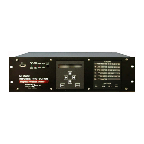
- Page 2 PROTECTION Intertie Protection M-3520 Integrated Protection System ® Unit shown with optional HMI and Target modules • Integrated Protection System for DR/DG Intertie, Providing: Loss of parallel utility operation protections Abnormal power flow protections Comprehensive suite of phase and ground fault backed protections...
- Page 3 M-3520 Intertie Protection Relay Standard Functions • Sync check with Phase, ΔV and ΔF with deadline/deadbus options (25) • Phase undervoltage (27) protection • Neutral over/undervoltage (59G/27G) protection • Sensitive dual-setpoint, reverse power detection (32) • Sensitive negative-sequence overcurrent protection and alarm (46) •...
- Page 4 M-3520 Intertie Protection Relay STANDARD FUNCTIONS Device Setpoint Number Function Ranges Increment Accuracy † Sync Check Sync Check Sync Check Sync Check Sync Check Phase Angle Window 0° to 90° 1° 1° Upper Voltage Limit 60 to 140 V 0.5 V or 0.5%...
- Page 5 M-3520 Intertie Protection Relay STANDARD FUNCTIONS ( cont .) Device Setpoint Number Function Ranges Increment Accuracy † Instantaneous Phase Overcurrent Instantaneous Phase Overcurrent Instantaneous Phase Overcurrent Instantaneous Phase Overcurrent Instantaneous Phase Overcurrent Pickup 1.0 to 240.0 A 0.1 A 0.1 A or (0.2 to 48.0 A)
- Page 6 M-3520 Intertie Protection Relay STANDARD FUNCTIONS ( cont .) Device Setpoint Number Function Ranges Increment Accuracy † VT Fuse–Loss Detection VT Fuse–Loss Detection VT Fuse–Loss Detection VT Fuse–Loss Detection VT Fuse–Loss Detection A VT fuse loss condition is detected by using the positive and negative sequence components of the voltages and currents.
- Page 7 M-3520 Intertie Protection Relay STANDARD FUNCTIONS ( cont .) Device Setpoint Number Function Ranges Increment Accuracy † Reconnect Enable Time Delay Reconnect Enable Time Delay Reconnect Enable Time Delay Reconnect Enable Time Delay Reconnect Enable Time Delay Reconnect Delay 2 to 65500 Cycles 1 Cycle –1 to +3 Cycles or...
- Page 8 M-3520 Intertie Protection Relay OPTIONAL FUNCTIONS Device Setpoint Number Function Ranges Increment Accuracy † Phase Distance (dual–zone mho characteristic) Phase Distance (dual–zone mho characteristic) Phase Distance (dual–zone mho characteristic) Phase Distance (dual–zone mho characteristic) Phase Distance (dual–zone mho characteristic) 0.1 to 100.0 Ω...
- Page 9 M-3520 Intertie Protection Relay Configuration Options The M-3520 Intertie Protection Relay can be purchased with standard protective functions or as a base system with reduced functionality. The user can also select optional protective functions as required to expand the functionality of the Standard Protection System or Base System to satisfy specific application needs.
- Page 10 M-3520 Intertie Protection Relay Control/Status Inputs The control/status inputs, INPUT1 through INPUT6, can be programmed to block any of the relay functions, trigger the oscillographic recorder or operate one or more outputs. The control/status inputs are designed to be connected to dry contacts and are internally wetted with a 24 V dc power supply. To provide breaker status LED indication on the front panel, the INPUT1 control/status input contact should be connected to the 52b breaker status contact.
- Page 11 The targets can be reset with the TARGET RESET pushbutton if the trip conditions have been removed. The OUTPUT LEDs indicate the status of the programmable output contacts. The module connects to the M-3520 Intertie Protection unit. Type Tests and Standards...
- Page 12 See M-3520 Instruction Book, Appendix E, Layup and Storage for additional information. Patent & Warranty The M-3520 Intertie Protection Relay is covered by U.S. Patents 5,592,393 and 5,224,011. The M-3520 Intertie Protection Relay is covered by a five year warranty from date of shipment. Specification subject to change without notice. –11–...
- Page 13 M-3520 Intertie Protection Relay –12–...
- Page 14 This function is available as a Typical standard protective function. Connection Diagram This function is available as a optional protective function. Note: M-3520 may be purchased as a Utility base protection system with 59, 27, 81O/U,79 and 60FL functions only. System M-3520...
- Page 15 M-3520 Intertie Protection Relay M-3520 Typical Three-line Connection Diagram Alternate VT Connection M-3520 M-3520 M-3520 M-3520 M-3520 IN 1 IN 2 IN 3 Self- OUT1 Test Self- Power Alarm 52-1 Test Trip Other Alarm Status Inputs Failure Alarm Alternate Phase VT...
- Page 16 M-3520 Intertie Protection Relay 17.50 [44.45] 17.31 [43.97] ACTUAL 5.21 [13.23] 5.28 [13.41] ACTUAL Rear View RECOMMENDED CUTOUT WHEN RELAY IS NOT USED AS STANDARD RACK MOUNT 10.20 [25.91] 19.00 [48.26] 18.58 [47.19] 17.78 [45.16] 0.40 [1.02] x 0.27 [0.68] SLOT (4x) 2.35 [5.96]...
- Page 17 RECOMMENDED CUTOUT WHEN RELAY IS NOT USED AS STANDARD RACK MOUNT Optional Vertical Mount Chassis Figure 5 Vertical Mounting Dimensions BECKWITH ELECTRIC CO., INC. 6190 – 118th Avenue North • Largo, Florida 33773–3724 U.S.A. Phone (727) 544-2326 • FAX (727) 546-0121 E-MAIL marketing@beckwithelectric.com ©...
- Page 18 Failure to do so will violate standards for safety in the design, manufacture, and intended use of the product. Qualified personnel should be the only ones who operate and maintain this equipment. Beckwith Electric Co., Inc. assumes no liability for the customer’s failure to comply with these requirements.
- Page 19 PRODUCT CAUTIONS Before attempting any test, calibration, or maintenance procedure, personnel must be completely familiar with the particular circuitry of this unit, and have an adequate understanding of field effect devices. If a component is found to be defective, always follow replacement procedures carefully to that assure safety features are maintained.
-
Page 20: Table Of Contents
Table of Contents TABLE OF CONTENTS M-3520 Intertie Protection Instruction Book Chapter 1 Introduction Instruction Book Contents ..............1–1 M-3520 Intertie Protection ..............1–2 Accessories ..................1–4 Chapter 2 Application Introduction..................2–1 System Diagrams ................2–2 Configuration ..................2–4 Functions .................... 2–4 Special Input/Output Considerations ........... - Page 21 Installation ................... 4–2 Installing IPScom ................4–2 Installing IPSutil .................. 4–2 Installing the Modems ................. 4–2 Setting Up the M-3520 Intertie Protection Relay for Communication . 4–3 Multiple Systems Setup ..............4–4 Serial Multidrop Network Setup ............4–4 Operation .................... 4–5 Activating Communications ..............
- Page 22 Table of Contents Chapter 4 Operation (Computer) ( cont ) Cautions .....................4–15 Checkout Status/Metering ..............4–16 Keyboard Shortcuts ................4–20 ™ IPSutil Communications Software ............4–21 M-3890 IPSutil ..................4–22 Installation and Setup .................4–22 Hardware Requirements ..............4–22 Installation ..................4–22 System Setup ..................4–22 Overview.....................4–22 Comm Menu ..................4–22 Relay Comm ..................4–23 Clock ....................4–24 Security Menu ..................4–24...
- Page 23 M-3520 Instruction Book Chapter 6 Testing Automatic Calibration................6–10 Input Configurations ................6–11 Functional Test Procedures ..............6–12 21 Phase Distance (#1, #2) ..............6–13 25 Sync Check ...................6–15 27 Undervoltage, 3 Phase (#1, #2) .............6–17 27G Undervoltage, Neutral ..............6–18 32 Directional Power, #1 or #2 ............6–19 46DT Negative Sequence Overcurrent Definite Time ......6–21...
- Page 24 Table of Contents Figures Page Chapter 1 M-3520 Front & Rear Panels .............. 1–3 M-3915 Target Module ..............1–4 M-3931 Human-Machine Interface ............. 1–4 Chapter 2 One-Line Functional Diagram ............. 2–2 Three-Line Connection Diagram ............2–3 Phase Distance (21) Zones of Protection ........... 2–8 Phase Distance (21) Function Applied for System Phase Faults ..
- Page 25 2-35 M-3822 IPScom for Windows Rate of Change of Frequency (81R) Setpoint Ranges ..... 2–47 Chapter 3 M-3520 Front Panel ................3–4 Screen Message Menu Flow .............. 3–4 Main Menu Flow ................. 3–5 Setup System Menu ................3–7 Communication Data & Unit Setup Menu ........... 3–9 Chapter 4 ®...
- Page 26 Setup Dialog Box ................4–25 4-29 Monitor Status Dialog Screen ............4–26 Chapter 5 M-3520 Mounting Dimensions – Horizontal Chassis ......5–2 M-3520 Mounting Dimensions – Vertical Chassis ......5–3 (H2) Mounting Dimensions ..............5–4 (H3) Mounting Dimensions for GE L-2 Cabinet ........5–5 External Connections ................
- Page 27 Communication Data & Unit Setup Record Form – As Shipped ..A–13 Functional Configuration Record Form – As Shipped ....A–15 Setpoint & Timing Record Form – As Shipped ....... A–17 Appendix B Null Modem Cable for M-3520 ............B–2 RS-232 Fiber Optic Network ............... B–3 RS-485 Networks ................B–4 viii...
- Page 28 IEC Curve #3 Extremely Inverse ............. D–10 IEC Curve #4 Long-Time Inverse ............ D–11 Tables Page Chapter 1 M-3520 Device Functions ..............1–2 Chapter 2 Impedance Calculation ............... 2–7 Delta/Wye Transformer Voltage-Current Pairs ......... 2–25 Typical Shunt Resistor Values ............2–33 Chapter 4 Windows Keyboard Shortcuts ............
- Page 29 Error Codes ..................C–1 C-1B Error Codes ..................C–2 Appendix D D-1A M-3520 Inverse Time Overcurrent Relay Characteristic Curves ..D–2 D-1B M-3520 Inverse Time Overcurrent Relay Characteristic Curves ..D–3 © Beckwith Electric Co. 800-3520-IB-09MC1 10/07 Printed in U.S.A.
-
Page 30: Chapter 1 Introduction
It further describes the handbook. It enumerates the functional capabilities procedures for entering all required data to the of the M-3520 Intertie Protection Relay and provides M-3520. a list (see Table 1-1) of device functions. This chapter also describes the accessories that may... -
Page 31: M-3520 Intertie Protection
ANSI/IEEE C37.2-1991, Standard Electric Power Systems Device Function Numbers. This chapter provides step-by-step test procedures for each M-3520 function as well as the diagnostic Six control/status input contacts (located on rear mode procedures and the autocalibration procedure side of unit) can be programmed to block any relay using the HMI. - Page 32 Module (HMI), all functions can be set or examined communications ports. The front-panel port, COM1, via a local, menu-driven 2-line by 24-character is used to locally set and interrogate the M-3520 via display. The HMI also provides the capability for a portable computer. The second RS-232 port, COM2, local metering of various quantities, including is provided at the rear of the unit.
-
Page 33: Accessories
M-3520 Instruction Book M-3931 Human-Machine Interface (HMI) Accessories The optional HMI module, shown in Figure 1-3, provides a means to interrogate the M-3520 and to input ® A copy of IPScom communication software is settings, access data, etc. directly from the front of shipped with each M-3520 Intertie Protection Relay. -
Page 34: Introduction
This chapter is designed to assist in the application This chapter provides information for the person or aspects of the Intertie Protection system. Detailed group responsible for the application of the M-3520 information on the relay functions, configuration, Intertie Protection Relay. Individual relay functions... -
Page 35: System Diagrams
This function is available as a Typical standard protective function. Connection Diagram This function is available as a optional protective function. Note: M-3520 may be purchased as a Utility base protection system with 59, 27, 81O/U,79 and 60FL functions only. System M-3520... - Page 36 Application - 2 M-3520 Typical Three-line Connection Diagram Alternate VT Connection M-3520 M-3520 M-3520 M-3520 M-3520 IN 1 IN 2 IN 3 Self- OUT1 Test Self- Power Alarm 52-1 Test Trip Other Alarm Status Inputs Failure Alarm Alternate Phase VT...
-
Page 37: Configuration
Configuration Functions The following functions can be configured using enable/disable output, and status input blocking Configuring the M-3520 Intertie Protection Relay designations: consists of enabling the relay functions to be used in a particular application. Once the output contacts + 21 Phase Distance zone #1, zone #2 (OUT1–8) are designated, each function will be... -
Page 38: System Setup
Application - 2 System Setup The system setup consists of defining common delay settings for particular functions. The values or information such as CT and VT ratios, nominal voltage selections shown below are only examples. Record and current ratings, VT configuration, phase rotation, and communicate the following information using the etc. - Page 39 M-3520 Instruction Book Selects the active state of the six status inputs. When ACTIVE INPUT OPEN/close highlighted (uppercase), the active state is an open i6 i5 i4 I3 i2 i1 circuit. When lowercase, the active state is closed cir- cuit (default)
-
Page 40: Setpoints And Time Settings
Application - 2 Setpoints and Time Settings 21 Phase Distance The phase distance function, designed for system When the Dispersed Generation (DG) is connected phase fault protection, is implemented as a two- to the system through a delta/wye transformer, zone mho characteristic. Three separate distance proper voltages and currents (equivalent to the high elements are implemented to detect AB, BC, and side of the transformer) must be used in order for... - Page 41 M-3520 Instruction Book Protected Range Zone 2 Protected Range Zone 1 M-3520 Figure 2-3 Phase Distance (21) Zones of Protection Zone 2 Transmission Line Zone 1 Circle Diameters Transformer System Impedance Angle –R –jX Figure 2-4 Phase Distance (21) Function Applied for System Phase Faults...
- Page 42 Application - 2 All primary impedances (Z ) must be reflected to relay quantities (Z ). The primary ohms (Z ) on the generator base needs to be multiplied by the ratio of the current transformer ratio (R ) to the voltage transformer ratio (R x (R ÷...
- Page 43 M-3520 Instruction Book (21) - PHASE DISTANCE Circle Diameter: 0.1 Ohms 100.0 Ohms Offset: -100.0 Ohms 100.0 Ohms Impedance Angle: Save Delay: 1 Cycle 8160 Cycles OUTPUT Blocking Input Cancel Circle Diameter: 0.1 Ohms 100.0 Ohms Offset: -100.0 Ohms 100.0 Ohms...
- Page 44 Application - 2 25 Sync Check Input Enable screen, and both the Dead V1 and Dead V2 elements are enabled, the dead check The Synchronism (Sync) Check function is used to timer will start when INPUT2 is activated, and either ensure that the voltage magnitude, phase angle V1 dead/V2 hot or V1 hot/V2 dead.
- Page 45 M-3520 Instruction Book Delta V and Delta F Check Logic With Delta V AND Delta F Enabled (V 1 - V 2 ) < Delta V Limit Delta V Is Enabled Phase Angle Check Logic (F 1 - F 2 ) < Delta F Limit >...
- Page 46 Application - 2 Sync Check (25) Function Logic Phase Angle, Delta V and Delta F Logic Dead Line/Dead Bus Logic From Sync Figure 2-6 Check Dead Line/Dead Bus Timer Dead Check Input Initiate Logic Check Timer Output Seal In Timer 25 Output Contact (79) Supervise (25) Function Logic...
- Page 47 M-3520 Instruction Book If this function is enabled, the following settings are applicable: If enabled, 79 timer will control 25 function. 79 SUPERVISE 25 disable ENABLE Phase angle setting. 25 PHASE LIMIT ________ Degrees Upper voltage limit for voltage acceptance.
-
Page 48: Sync Check
Application - 2 Externally controlled dead closing. 25 DEAD INPUT ENABLE i6 i5 i4 I3 i2 i1 Dead delay timer setting. 25 DEAD DELAY ________ Cycles (25) - SYNC CHECK Phase Angle Window: Upper Voltage Limit: 60 V 140 V Lower Voltage Limit: 40 V 120 V... -
Page 49: Undervoltage, 3-Phase
M-3520 Instruction Book 27 Undervoltage, 3 Phase Voltage is commonly suggested as an efficient essentially sinusoidal, making the use of rms value means to protect against islanding. Notably, unless of fundamental frequency component as the the DG includes very high-speed generator measurement for this function. -
Page 50: Directional Power
A power import (forward) or negative (reverse). and export convention that considers DG, Utility and the M-3520 perspectives is also included. The a. Positive pick up value – Places the directional power function provides two power pick up point in the forward power... - Page 51 M-3520 Instruction Book REVERSE OVERPOWER REVERSE UNDERPOWER TRIP TRIP TRIP TRIP Pick up Pick up Reverse --- Relay --- Forward Reverse --- Relay --- Forward Import --- DG --- Export Import --- DG --- Export Export --- Utility --- Import...
- Page 52 Application - 2 If this function is enabled, the following settings are applicable 32 #1 PICKUP ________ PU 32 #1 OVER/UNDER POWER over_power under_power 32 #1 DELAY ________ Cycles 32#1 THREE PHASE DETECT This screen present if VT configuration is set Line-to-Ground. disable ENABLE 32 #2 PICKUP ________...
- Page 53 M-3520 Instruction Book 46 Negative Sequence Overcurrent The inverse time function can be selected as one of The Negative Sequence Overcurrent function pro- the eight curve families: definite, inverse, very vides protection against possible damage due to inverse, extremely inverse, and four IEC curves.
-
Page 54: Negative Sequence Overcurrent
Application - 2 (46) - NEGATIVE SEQUENCE OVERCURRENT Def. Time Pickup: 0.10 Amp 20.00 Amps Delay: 1 Cycle 8160 Cycles Save OUTPUT Blocking Input Cancel Inv. Time 0.50 Amp Pickup: 5.00 Amps Delay: 11.0 Curves Definite Time Inverse Very Inverse Extremely Inverse IECI IECVI... -
Page 55: Negative Sequence Overvoltage
M-3520 Instruction Book 47 Negative Sequence Overvoltage The Negative Sequence Overvoltage function 47 provides protection for voltage imbalance and reverse phase sequence. If this function is enabled, the following settings are applicable: 47#1 PICKUP A pickup setting in the range of 10 to 30 V can reliably detect open phases and reverse phase sequence. -
Page 56: Instantaneous Overcurrent, 3-Phase
Application - 2 50 Instantaneous Overcurrent, 3-Phase The Instantaneous Phase (50) functions provide fast tripping times for high fault currents. The settings for 50 should be chosen such that they will not respond to faults on the adjacent system. If this function is enabled, the following setting is applicable: 50 PICKUP ________ Amps (50) - INSTANTANEOUS PHASE OVERCURRENT... -
Page 57: Instantaneous Overcurrent, Neutral
M-3520 Instruction Book 50G Instantaneous Overcurrent, Neutral The Instantaneous Neutral Overcurrent (50G) function provides fast tripping times for high fault currents. The settings for 50G should be chosen such that they will not respond to faults on the adjacent system. -
Page 58: Inverse Time Overcurrent With Voltage Control Or Voltage Restraint
51VR or 51VC included. The eight curve families to be chosen element. The M-3520 can internally determine the from are definite, inverse, very inverse, extremely equivalent high-side voltages of the delta/wye unit inverse, and four IEC curves. - Page 59 M-3520 Instruction Book Figure 2-16 Voltage Restraint (51V) Characteristic If this function is enabled, the following settings are applicable: Sets phase current pickup for 51V. 51V PICKUP ________ Amps Selects one of the eight inverse time curves as shown in 51V CURVE Appendix D, Figures D-1 through D-8.
- Page 60 Application - 2 (51V) - INVERSE TIME OVERCURRENT W/VOLTAGE CONTROL OR VOLTAGE RESTRAIN Pickup: 0.50 Amp 12.00 Amps Delay: 11.0 Save Curves Definite Time Inverse Very Inverse Extremely Inverse IECI IECVI IECEI IECLTI Cancel Voltage Control: 180 V Disable Voltage Control Voltage Restrain OUTPUT Blocking Input...
-
Page 61: Inverse Time Neutral Overcurrent
IEC curves. The operator selects the time dial within each family setting and pickup setting through the M-3520 menu. If this function is enabled, the following settings are applicable: 51G PICKUP Sets ground current pickup. -
Page 62: Peak Overvoltage
Application - 2 59I Peak Overvoltage Most overvoltage relays operate based on the RMS Because it is necessary to describe voltage for this value of voltage. There is, however, a system purpose in terms of the peak value of voltage (not phenomenon known as ferroresonance which may RMS), it is convenient to define the parameter occur on a lightly loaded, islanded system. -
Page 63: Overvoltage, 3-Phase
M-3520 Instruction Book 59 Overvoltage, 3-Phase Voltage is commonly suggested as an efficient IEEE suggests that the first setpoint (with a short means to protect against islanding. Notably, unless time delay) be set up at 150% of the nominal voltage,... -
Page 64: 27G Overvoltage/Undervoltage, Neutral Circuit Or Zero Sequence
Application - 2 59G/27G Overvoltage/Undervoltage, Neutral Circuit or Zero Sequence The neutral Overvoltage/Undervoltage functions 59G/ Applications of 59G/27G, shown in Figures 2-27 and 27G provide protection for ground faults on the 2-28, are for detecting ground faults on the utility system. - Page 65 M-3520 Instruction Book ® Figure 2-22 M-3822 IPScom for Windows™ Neutral Undervoltage (27G) Setpoint Ranges Path: Relay Menu/Setup/Setpoints/(27G) Neutral Undervoltage COMMAND BUTTONS Save Saves all information to the relay. Cancel Returns the user to the previous window; any changes to the displayed information are lost.
- Page 66 Application - 2 Ground Fault Detection using 59G and Broken- Delta VTs The 59G may be used to detect system phase In this case, voltage at 59G in Figure 2-24 will be voltage unbalance in conjunction with three VTs. zero so long as the three-phase voltages are To do so, the VT secondaries are connected in balanced, but will rise above zero with any zero- “broken”...
- Page 67 M-3520 Instruction Book Ground Fault Detection Using 27G and 59G with One VT An alternate, but not recommended, scheme uses For this scheme to work, the capacitance to ground of the lines must be fairly closely balanced and the 27G and 59G functions with one VT rated for...
-
Page 68: 60Fl Fuse Loss
60FL INPUT INITIATE any of the externally-connected contacts (across these FL i6 i5 i4 i3 i2 i1 M-3520 inputs) will start the associated time delay to the 60FL function operation. The time delay is to be set to coordinate for conditions... - Page 69 M-3520 Instruction Book 67 Phase Directional Overcurrent For intertie protection applications, the phase phase detection is disabled, and any one phase directional overcurrent relay allows greater current exceeds pickup, timing will begin. The selectivity for utility system faults, since the...
- Page 70 Application - 2 If this function is enabled, the following settings are applicable: Pickup value for the 67DT element. 67DT PICKUP ________ Amps Directional discrimination enable. When disabled, this func- 67DT DIRECTIONAL ELEMENT tion will work like a standard overcurrent function (50DT). disable ENABLE 67DT THREE PHASE DETCT When enabled, all three phase currents must exceed the...
-
Page 71: Phase Directional Overcurrent
M-3520 Instruction Book (67) - PHASE DIRECTIONAL OVERCURRENT Def. Time Pickup: 1.0 Amp 240.0 Amps Delay: 1 Cycle 8160 Cycles Three Phase Detection: Enable Disable Phase Directional Element: Enable Disable OUTPUT Blocking Input Save Inv. Time 0.50 Amp Pickup: 12.00 Amps Time Dial: 11.0... -
Page 72: Residual Directional Overcurrent
Application - 2 67N Residual Directional Overcurrent Type 3: 3V and 3I , where V and I are negative The neutral directional overcurrent (67N) function sequence voltage and current, respectively. provides protection from ground faults. This function includes an inverse time overcurrent element, and Type 4: I and 3I , where I... - Page 73 M-3520 Instruction Book Figure 2-28 M-3822 IPScom® for Windows™ Residual Directional Overcurrent (67N) Setpoint Ranges Path: Relay Menu/Setup/Setpoints/(67N) Residual Directional Overcurrent COMMAND BUTTONS Save Saves all information to the relay. Cancel Returns the user to the previous window; any changes to the displayed information are lost.
-
Page 74: Out Of Step
Application - 2 78 Out-of-Step The Out-of-Step function (78) is used to protect the Consider, for example, Figure 2-29. If the out-of-step generator from out-of-step or pole slip conditions. swing progresses to impedance Z ), the MHO Out-of-Step conditions can occur when faults are element and the blinder A element will both pick up. - Page 75 M-3520 Instruction Book 78 DIAMETER ________ Ohms A negative or positive offset can be specified to offset 78 OFFSET the mho circle from the origin. ________ Ohms 78 BLINDER IMPEDANCE The blinder impedance should be programmed less ________ Ohms than the set diameter.
-
Page 76: Reconnect Enable Time Delay
Application - 2 79 Reconnect Enable Time Delay The reconnect relay is a permissive programmable For example: If function 27#1 is programmed to output that may be set to close from 1 to 8160 output 5 (for alarm), 27#2 to output 1 (for trip), 81#1 cycles after all tripping functions are within limits. - Page 77 M-3520 Instruction Book If this function is enabled, the following settings are applicable: 79 RECN INITIATE (TRIP) Designated trip output selection. All trip outputs must drop o8 o7 o6 o5 o4 o3 O2 o1 out to start reconnect timer. 79 DELAY Reconnect time delay.
- Page 78 Application - 2 81 Frequency When Dispersed Generation (DG) is suddenly A second school of thought advocates that the DG islanded, the frequency will quickly shift from 60.0 Hz should definitely not be severed from the utility low (except for the improbable case of an exact frequency operation while the frequency remains generation and load match), making the as high as 59.5 Hz.
-
Page 79: Frequency
M-3520 Instruction Book (81) - FREQUENCY Pickup: 50.00 Hz 67.00 Hz Delay: 2 Cycles 65500 Cycles OUTPUT Blocking Input Pickup: 50.00 Hz 67.00 Hz Delay: 2 Cycles 65500 Cycles OUTPUT Blocking Input Save Pickup: 50.00 Hz 67.00 Hz Cancel Delay:... -
Page 80: Rate Of Change Of Frequency
Application - 2 81R Rate of Change of Frequency The Rate of Change of Frequency function can be The function also has an automatic disable feature, used to detect islanding conditions. When the DG to disable 81R function during unbalanced faults (Dispersed Generation) is islanded, the frequency and other system disturbances. -
Page 81: Oscillograph Recorder
M-3520 Instruction Book Oscillograph Recorder When configured with a specific post trigger delay, The oscillograph recorder provides comprehensive the oscillographic record will show post-trip data in data recording of all monitored waveforms (voltage, addition to pre-trip data, and keeps a snapshot of... -
Page 82: Target History Recorder
O7 O6 O5 O4 O3 O2 O1 IRIG-B Time Sync The M-3520 Intertie Protection Relay has the ability to accept either a modulated or demodulated IRIG-B signal. The modulated signal is connected using the rear panel BNC connector, and is the default configuration. - Page 83 M-3520 Instruction Book This Page Left Intentionally Blank 2–50...
-
Page 84: Chapter 3 Operation (Front Panel)
M-3520 Intertie Protection Relay. value. These menus consist of two lines. The bottom line shows lower case abbreviations of... -
Page 85: Arrow Buttons
Pressing and holding the TARGET RESET button programmable value with the currently displayed displays the present pickup status of the M-3520 value, or to select one of several displayed options, functions on the target indicators. -
Page 86: Default Message Screens
Operation (Front Panel) – 3 The M-3520 has three levels of access codes, ting parity (none, odd or even) and stop bit (1, which determine the extent of access to M-3520 2), if configured for MODBUS protocol. Detailed functions for each user. The higher the Level information on the use of the communications number, the greater access permitted. - Page 87 OUT 6 OUT 8 Made in U.S.A. M-3931 M-3915 Human-Machine Interface Target Module Module –Optional– –Optional– Figure 3-1 M-3520 Front Panel Self-Tests POWER ON SELFTESTS BECKWITH ELECTRIC CO. -TRGT- 08/01/98 10:19:12 XXXXXXXX M-3520 Trip #47 Blanked Screen LED Test Default Message Screens...
- Page 88 Operation (Front Panel) – 3 VOLTAGE RELAY CURRENT RELAY FREQUENCY RELAY POWER RELAY VOLT curr freq pwr volt CURR freq pwr volt curr FREQ pwr volt curr freq PWR V.T. FUSE_LOSS RELAY SYNC CHECK RELAY RECONNECT RELAY GND DIFFERENTIAL RELAY PHASE DISTANCE RELAY LOSS OF FIELD RELAY dist FUSE sync...
-
Page 89: Initial Setup Procedure/Settings
Enter the desired information for the proceed. In such a case, the error code oscillograph recorder. should be noted and Beckwith Electric contacted. A list of error codes and their Enter the desired information for the descriptions are provided in Appendix target recorder. - Page 90 Operation (Front Panel) – 3 SETUP SYSTEM f config SYS stat dmd g NOMINAL VOLTAGE PULSE RELAY V.T. PHASE RATIO VOLT curr vt sync phaseg f PULSE seal in y_dtx g f VT vt_v2 vt_n ct ct_n NOMINAL VOLTAGE PULSE RELAY V.T.
-
Page 91: Communication Data
Figure 3-5 is a sample of the Communication Data input for this Section. Settings are self explanatory, & Unit Setup Record Form. Refer to the column on and are required for proper operation of the M-3520 the left for communication data. It is organized in relay. - Page 92 USER LOGO LINE 1 fLOGO1 logo2 out alrm g PROCESSOR WILL RESET! ENTER KEY TO CONTINUE USER LOGO LINE1 COMMUNICATION ACCSS CODE BECKWITH ELECTRIC CO. f ACCSS COMMUNICATION ACCSS CODE USER LOGO LINE 2 9999 flogo1 LOGO2 out alrm g...
-
Page 93: Setpoints And Time Settings
M-3520 Instruction Book Setpoints and Time Settings Target History Recorder The general information that is required to complete The VIEW TARGET HISTORY menu selection the input data in this section includes individual enables the user to review the targets for the relay function: previous 32 target conditions. -
Page 94: Checkout Status/Metering
Operation (Front Panel) – 3 Checkout Status/Metering The relay has two menu selections concerning IN/OUT STATUS monitoring status and demand values. This section Status of input and output contacts describes the operation of these selections. The following timer status can also be monitored: Status/Metering VOLTAGE TIMER Access the STATUS menu as follows:... - Page 95 M-3520 Instruction Book This Page Intentionally Left Blank 3–12...
-
Page 96: Chapter 4 Operation (Computer)
Communications Software ........4–19 Hardware Requirements This chapter contains information on configuring and interrogating the M-3520 Intertie Protection Relay IPScom will run on any IBM PC-compatible computer using a personal computer running the M-3822 that provides at least the following: IPScom Communications Software package. -
Page 97: Use Of Ipscom
Pin-outs for communication cables in the new subdirectory IPScom are provided in Appendix B. (C:\\Becoware\\Ipscom). Use of IPScom and M-3520 Intertie Protection Installing IPSutil™ Relay using Direct Serial Connection IPSutil is utility software used to program system- In order to use IPScom to communicate with the level parameters for units shipped without the M-3931 relay using direct serial connection, a serial “null... -
Page 98: Setting Up The M-3520 Intertie Protection Relay For Communication
M-3931 HMI Module. ■ ■ ■ ■ ■ NOTE: Communication is inhibited while the relay is in local mode (being accessed using the HMI). To ensure the M-3520 is available for remote communication, press ENTER at the EXIT LOCAL MODE... -
Page 99: Multiple Systems Setup
If two or more units share the same address, Other communication methods are possible using corrupted communications will result. the M-3520 Intertie Protection Relay. An Application Note, “ Serial Communication with Beckwith Electric’s Integrated Protection System Relays ” is available from the factory, or from our website at www.beckwithelectric.com. -
Page 100: Operation
Operation (Computer) – 4 Choose the COMM menu selection. Operation Complete the appropriate information on the window for the relay to be addressed. Activating Communications a. If communication is through a After the relay has been set up, the modems modem, choose the Modem initialized, and IPScom installed, communication is command button to expand the... - Page 101 M-3520 Instruction Book M-3520 User Logo Lines Relay Type / Unit Identifier Unit Address Figure 4-3 IPScom® Menu Selections 4–6...
-
Page 102: Overview
Since IPScom can be used with several Beckwith protection systems in addition to the M-3520 Intertie The Print and Printer Setup commands allow user Protection Relay, the format and contents of a file... - Page 103 M-3520 Instruction Book control on modem communications, such as window will appear showing access level #3 was communications where modem switch is involved granted. Otherwise, another dialog box will appear at the remote site. to prompt the user to enter the access code in order to establish the communication.
-
Page 104: Relay Menu
Operation (Computer) – 4 Relay Menu The Setup submenu provides three commands: Setup System, Setpoints, and Set Date/Time. The Relay menu provides access to the windows The Setup Relay command displays a dialog box used to set, monitor, or interrogate the relay. Four (see Figure 4-6) which allows the input of pertinent submenus are provided: Setup, Monitor, Targets information regarding the system on which the... - Page 105 M-3520 Instruction Book The Setpoints command displays the Relay Set- points dialog box (see Figure 4-7) from which the individual relay function dialog boxes can be accessed. Choosing a relay function button (#46, for example), will display the corresponding func- tion dialog box (see Figure 4-8).
- Page 106 Operation (Computer) – 4 The Relay Setpoints dialog box gives access to two additional dialog boxes: All Setpoints Table and Configure. Choosing the Display All command button displays the All Setpoints Table dialog box (see Fig. 4-9). This dialog contains a list of settings for each relay within a single window to allow scrolling through all relay setpoint configuration values.
- Page 107 M-3520 Instruction Book Choosing the Configure command button displays scrolling dialog box to an individual relay function a dialog box (see Fig. 4-10), which contains a chart dialog box and return to the scrolling dialog box of programmed input and output contacts, in order again.
- Page 108 The Monitor submenu provides access for reviewing allows system date and time to be set, or system the present status of the M-3520’s measured and clock to be stopped. This dialog box also displays calculated values, other real-time parameters and...
-
Page 109: Window Menu
Figure 4-12 Target Dialog Box The Write File To Relay submenu is used to write the data to the M-3520 relay. The Read Data From Path: Relay menu / Targets submenu / Display command Relay submenu is used to retrieve the data from the relay to the computer for display. -
Page 110: Cautions
If Serial Port Connections there is any question about compatibility, contact Beckwith Electric. If the serial port is connected to something other than a modem, and an IPScom modem command is executed, the results are unpredictable. In some System Priority cases, the computer may have to be reset. -
Page 111: Checkout Status/Metering
M-3520 Instruction Book Checkout Status/Metering IPSCOM - [Primary Status] (1) BECKWITH ELECTRIC CO. M-3520 VOLTAGES Peak Voltages CURRENTS POWERS (va) (var) FREQUENCY ROCOF OUTPUTS INPUTS BREAKER Figure 4-14 Primary Status Dialog Box Path: Relay menu/Monitor submenu/ Primary Status window These are calculated values based on the VT and CT inputs. - Page 112 Operation (Computer) – 4 IPSCOM - [Secondary Status] (1) BECKWITH ELECTRIC CO. M-3520 Ω Ω Ω Ω Ω 327.67 + j327.67 Ω 327.67 + j327.67 Ω 327.67 + j327.67 Figure 4-16 Phase Distance Dialog Box Path: Relay menu / Monitor submenu / Phase Distance window...
- Page 113 M-3520 Instruction Book Phasor Diagram Figure 4-18 Phasor Diagram Path: Relay menu/Monitor submenu/Phasor Diagram COMMAND BOXES Voltage – Select to display voltage signals. Currents – Select to display current signals Freeze – When checked, visible data will not be updated.
- Page 114 Operation (Computer) – 4 Out of Step Figure 4-20 Out-of-Step Screen 4–19...
-
Page 115: Keyboard Shortcuts
M-3520 Instruction Book Keyboard Shortcuts Keyboard Shortcuts SYSTEM KEYS ® These keys can be used within Windows and IPScom Alt-Tab To switch between applications. Ctrl-Esc To open Task List dialog box. Ctrl-Tab To switch between windows. Arrow Keys To select an application or group icon. -
Page 116: Ipsutil™ Communications Software
Operation (Computer) – 4 IPSutil™ Communications Software IPSutility ( Relay M-3520 D-00XX VX.XX.XX ) Help Comm Relay Comm Clock Security Miscellaneous Window Miscellaneous Setup Monitor Status RelayComm Advanced Comm Help Connect About... Exit Alt+F4 Clock Security Change Comm Access Code... -
Page 117: M-3890 Ipsutil
M-3520 Instruction Book M-3890 IPSutil™ interface. Units delivered without HMI’s are shipped with a set of factory default settings for various The M-3890 IPSutil Communication software parameters that the end user may wish to change. package provides communication with the Beckwith... -
Page 118: Relay Comm
Operation (Computer) – 4 Relay Comm IPSutility ■ ■ ■ ■ ■ NOTE: If COM1 baud rate is changed and the relay is reset, the new baud rate must be used to communicate with COM1 When Relay Comm menu is selected, the Relay The Exit submenu allows you to quit IPSutil™. -
Page 119: Clock
M-3520 Instruction Book Clock Security Menu When the Clock menu is selected, the Set Unit Date/Time dialog box appears, allowing the user to start or stop the clock in the relay, and change the The Security Menu allows you to set the date or time (See Figure 4-25). -
Page 120: Miscellaneous Menu
Operation (Computer) – 4 Miscellaneous Menu Change Level Access Code The Miscellaneous menu allows you to set and monitor some of the relay parameters. The Setup feature (Figure 4-28) allows the user to change the Logo information, test outputs, assign Figure 4-27 Change Level Access Code communication address and user control number, Dialog Box... -
Page 121: Help Menu
M-3520 Instruction Book Help Menu The Monitor Status feature (See Figure 4-29) allows the user to monitor and clear the error code counters, monitor the check sums, and to view inputs test status. Note that powerloss counter cannot be cleared. -
Page 122: Chapter 5 Installation
If during the commissioning of the relay, additional tests are desired, refer to Chapter 6, Testing. The operation of the M-3520 Intertie Protection Relay, including the initial setup procedure, is described in Chapter 3, Operation (Front Panel). If the relay is not provided with an HMI module, refer to Chapter 4, Operation (Computer). - Page 123 10.20 [25.91] 19.00 [48.26] 18.58 [47.19] 17.78 [45.16] 0.40 [1.02] x 0.27 [0.68] SLOT (4x) 2.35 [5.96] 1.35 [3.42] Standard 19" Horizontal Mount Chassis ■ NOTE: Dimensions in brackets are in centimeters. Figure 5-1 M-3520 Mounting Dimensions – Horizontal Chassis 5–2...
- Page 124 18.58 [43.97] [47.19] Actual 17.78 [45.16] Rear View ■ NOTE: Dimensions in brackets are in centimeters. RECOMMENDED CUTOUT WHEN RELAY IS NOT USED AS STANDARD RACK MOUNT Optional Vertical Mount Chassis Figure 5-2 M-3520 Mounting Dimensions – Vertical Chassis 5–3...
- Page 125 M-3520 Instruction Book 1.91 [0.99] 2.25 [4.85] [5.71] .261 [0.66] Diameter 4 Holes 8.72 [22.15] Recommended Panel Cutout Dimensions 18.21 [46.25] 2.80 2.80 [7.12] [7.12] 19.00 [48.26] 8.72 [22.15] Max. Depth of Unit: 10.50 [26.67] 6.19 [15.72] n NOTE: Dimensions in brackets are in centimeters.
- Page 126 Installation – 5 6.13 [15.57] 5.56 1.04 [2.64] [14.12] .261 [0.66] Diameter 6 Holes 8.72 [22.15] Recommended Panel Cutout Dimensions 18.50 [46.99] 2.80 2.80 [7.12] [7.12] 20.78 [52.78] 15.56 [39.52] 8.72 [22.15] 7.78 [19.76] Max. Depth of Unit: 10.50 [26.67] 2.60 [6.60] 1.14...
-
Page 127: External Connections
Figure 5-5 provides an explicit view of all the external contacts, com-munications points, and power fuses of the M-3520 Intertie Protection Relay. ■ ■ ■ ■ ■ NOTE: Output contacts #1 through #4 are high- speed operation contacts. To fulfill UL and CSA requirements, terminal block connections must be made with No. - Page 128 Installation – 5 M-3520 Typical Three-line Connection Diagram Alternate VT Connection M-3520 M-3520 M-3520 M-3520 M-3520 IN 1 IN 2 IN 3 Self- OUT1 Test Self- Power Alarm 52-1 Test Trip Other Alarm Status Inputs Failure Alarm Alternate Phase VT...
-
Page 129: Commissioning Checkout
M-3520 Instruction Book Press ENTER to display positive Commissioning Checkout sequence voltage. The positive sequence voltage should be V y or V During field commissioning, perform the following procedure to ensure that the CT and VT connections POS SEQUENCE VOLTAGE are correct. - Page 130 Installation – 5 Press ENTER to display line currents (I Press ENTER to display the nominal ). Compare these currents with the system frequency: measured values using a meter. If there FREQUENCY BUS 1 is a discrepancy, check the CT 60.00 Hz connections to the rear terminal block of the unit.
-
Page 131: Circuit Board Switches And Jumpers
M-3520 Instruction Book Circuit Board Switches and Jumpers t a l t a l t t e t s i t s i t t e i t a t t e i t t t t e t t e i t c . - Page 132 Installation – 5 Figure 5-7 M-3520 Circuit Board 5–11...
- Page 133 M-3520 Instruction Book This Page Intentionally Left Blank 5–12...
- Page 134 Testing – 6 Testing Equipment and Test Setup ............6–2 Diagnostic Test Procedures ............6–3 Automatic Calibration ............... 6–10 Input Configurations ..............6–11 Functional Test Procedures ............. 6–12 21 Phase Distance (#1 or #2) ..........6–13 25 Sync Check ................. 6–15 27 Undervoltage, 3 Phase ............
-
Page 135: Equipment And Test Setup
5-4 for reference to the HMI and Connect power to the relay’s power input TARGETS controls and LEDs, and rear terminals 62 and 63. The M-3520 may be connections. configured with a high voltage power supply with a nominal voltage input of... -
Page 136: Diagnostic Test Procedures
Testing – 6 ✓ ✓ ✓ ✓ ✓ ✓ ✓ ✓ ✓ ✓ ✓ ✓ ✓ ✓ ✓ ✓ ✓ ✓ ✓ ✓ ✓ ✓ ✓ ✓ ✓ ✓ ✓ ✓ ✓ ✓ ✓ ✓ ✓ ✓ ✓ ✓ ✓ ✓... -
Page 137: Output Test (Relay)
M-3520 Instruction Book When testing in DIAGNOSTIC MODE is Use the right button to highlight ON in complete, press EXIT until the following uppercase letters, which signifies message appears: selection. The following is displayed: PRESS EXIT TO RELAY NUMBER 1... -
Page 138: Input Test (Status)
RESET Press ENTER. The following is displayed: TIME OSC. DIAG PS 1 INPUT NUMBER SYNC TRIG M-3520 INTERTIE PROTECTION Press ENTER. The following is displayed: INPUT NUMBER 1 CIRCUIT OPEN BECKWITH CO. INC. ELECTRIC Made in U.S.A. Connect IN RTN, terminal #11, to IN1, terminal #10. -
Page 139: Target Led Test
M-3520 Instruction Book Target LED Test Expanded I/O Test ■ ■ ■ ■ ■ NOTE: This test is not applicable to units that are This function is not implemented at this time. not equipped with the M-3915 Target Module. Button Test ■... -
Page 140: Display Test
2 connected to pin 3 and pin 7 connected to pin 8. When COM3 LOOPBACK TEST 4WIRE is displayed, press the right arrow button M-3520 until the following is displayed: COM1/COM2 COM3 ECHO TEST 2WIRE DB9P com1 com2 com3 COM3 Press ENTER. -
Page 141: Com3 Test (4Wire)
M-3520 Instruction Book Press ENTER. The following is displayed: COM3 LOOPBACK TEST 4 WIRE CONNECT LOOPBACK PLUG RS-232 to RS-485 converter or PC card (2 wire) On the rear of the unit, connect a jumper from terminal 1 to terminal 3 and from terminal 2 to terminal 4. -
Page 142: Flash Relay Ok Led
Testing – 6 Press ENTER again to toggle the clock. If Flash Relay OK LED the clock is running, it will stop. If clock The Flash Relay OK LED function is provided to has stopped, it will start. The clock stop enabled or disable the flashing of the Relay OK LED. -
Page 143: Automatic Calibration
M-3520 Instruction Book For units without the optional M-3931 HMI: Automatic Calibration It is possible to auto-calibrate Intertie Protection Relays that are not equipped with the optional M-3931 The relay has been fully calibrated at the factory. HMI. The procedure is similar to HMI equipped units: There is no need to recalibrate the unit prior to installation. -
Page 144: Input Configurations
Testing – 6 Polarity 47 Input Configurations Current 0° Input 1 The phase angles shown here represent leading angles as positive and lagging angles as negative. Polarity 49 Some manufacturers of test equipment use lagging Current =120 V ACs s s s s 120° -120°... -
Page 145: Functional Test Procedures
This section details the test quantities, inputs and During the lifetime of the relay, testing of individual procedures for testing each function of the M-3520 functions due to changes in application settings will Intertie Protection Relay. The purpose is to confirm be more likely than an overall testing routine. -
Page 146: Phase Distance (#1, #2)
Testing – 6 21 Phase Distance (#1 or #2) Line to Line VOLTAGE INPUTS: Configuration V1 CURRENT INPUTS: Configuration C1 TEST SETTINGS: Diameter Ohms (0.1 to 100) 1 Amp CT Rating (0.5 to 500.0) Offset Ohms (–100 to 100) 5 Amp CT Rating (–500.0 to 500.0) Impedance Angle Degrees... - Page 147 M-3520 Instruction Book 21 Phase Distance (#1 or #2) Line to Ground VOLTAGE INPUTS: Configuration V1 CURRENT INPUTS: Configuration C1 TEST SETTINGS: Diameter Ohms (0.1 to 100) 1 Amp CT Rating (0.5 to 500.0) Offset Ohms (–100 to 100) 5 Amp CT Rating (–500.0 to 500.0)
-
Page 148: Sync Check
Testing – 6 25 Sync Check VOLTAGE INPUTS: See Below CURRENT INPUTS: None TEST SETTINGS: 79 Supervise 25 Disable Phase Angle Limit Degrees (0 to 90) Voltage Limits Upper Limit Volts (60 to 140) Lower Limit Volts (40 to 120) Sync Check Delay Cycles (1 to 8160) - Page 149 M-3520 Instruction Book Delta Voltage Test : Set the Upper and Lower Voltage limits to their maximum and minimum values, respectively. Set V2 to 140 V and V1 to 80 V. Hold the TARGET RESET button in and slowly increase the voltage on V1 until Output Z LED operates, or the pickup indicator operates on the computer target screen.
-
Page 150: Undervoltage, 3 Phase (#1, #2)
Testing – 6 27 Undervoltage, 3 Phase (#1 or #2) VOLTAGE INPUTS: Configuration V1 CURRENT INPUTS: None TEST SETTINGS: Pickup Volts (5 to 180) Time Delay Cycles (1 to 8160) Programmed Outputs Output (1 to 8) Function 60FL Disable Function 27#1 or #2 Disable Functions 25, 79 Disable... -
Page 151: Undervoltage, Neutral
M-3520 Instruction Book 27G Undervoltage, Neutral VOLTAGE INPUTS: See Below CURRENT INPUTS: None TEST SETTINGS: Pickup Volts (5 to 180) Time Delay Cycles (1 to 8160) Programmed Outputs (1 to 8) Functions 59G, 79 Disable Disable functions as shown. Refer to Section 3.2, Configure Relay Data, for procedures. -
Page 152: Directional Power, #1 Or #2
Testing – 6 32 Directional Power, #1 or #2 (Line to Line) VOLTAGE INPUTS: Configuration V2 CURRENT INPUTS: Configuration C1 TEST SETTINGS: Pickup (–3.00 to +3.00) Time Delay Cycles (1 to 8160) Programmed Outputs (1 to 8) Function 32 (#1 or #2) Disable Functions 59, 59I, 60FL Disable... - Page 153 M-3520 Instruction Book 32 Directional Power, #1 or #2 (Line to Ground) VOLTAGE INPUTS: Configuration V1 CURRENT INPUTS: Configuration C1 TEST SETTINGS: Pickup (–3.00 to +3.00) Time Delay Cycles (1 to 8160) Programmed Outputs (1 or 8) Function 32 (#1 or #2)
-
Page 154: 46Dt Negative Sequence Overcurrent Definite Time
Testing – 6 46DT Negative Sequence Overcurrent Definite Time VOLTAGE INPUTS: None CURRENT INPUTS: Configuration C1 (MODIFIED) TEST SETTINGS: Pickup Amps (0.10 to 20.00) 1 Amp CT Rating (0.02 to 4.00) Time Delay Cycles (1 to 8160) Programmed Outputs Output (1 to 8) Function 46 Inverse Time Disable... -
Page 155: 46It Negative Sequence Overcurrent Inverse Time
M-3520 Instruction Book 46IT Negative Sequence Overcurrent Inverse Time VOLTAGE INPUTS: None CURRENT INPUTS: Configuration C1 (MODIFIED) TEST SETTINGS: Pickup Amps (0.5 to 5.00) 1 Amp CT Rating (0.1 to 1.00) Standard Inverse Time Curves Curve (1 to 4) Time Dial (0.5 to 11.0) -
Page 156: Negative Sequence Overvoltage
Testing – 6 47 Negative Sequence Overvoltage VOLTAGE INPUTS: Configuration V1 (Modified) CURRENT INPUTS: Configuration C1 TEST SETTINGS: Pickup Volts (5 to 180) Time Delay Cycles (1 to 8160) Programmed Outputs Output ( 1 to 8) Function 59, 27, 79 Disable ■... -
Page 157: Instantaneous Phase Overcurrent
M-3520 Instruction Book 50 Instantaneous Phase Overcurrent VOLTAGE INPUTS: None CURRENT INPUTS: Configuration C1 TEST SETTINGS: Pickup Amps (1.0 to 240.0) 1 Amp CT Rating (0.2 to 48.0) Programmed Outputs Output (1 to 8) Function 51V Disable Disable functions as shown. Refer to Section 3.2, Configure Relay Data, for procedures. -
Page 158: Instantaneous Phase Overcurrent, Neutral
Testing – 6 50G Instantaneous Overcurrent, Neutral VOLTAGE INPUTS: None CURRENT INPUTS: Configuration C2 TEST SETTINGS: Pickup Amps (0.5 to 240.0) 1 Amp CT Rating (0.1 to 48.0) Programmed Outputs Output (1 to 8) Function 51G Disable Disable functions as shown. Refer to Section 3.2, Configure Relay Data, for procedures. Confirm settings to be tested. -
Page 159: Inverse Time Overcurrent, Phase
M-3520 Instruction Book 51V Inverse Time Overcurrent, Phase VOLTAGE INPUTS: None CURRENT INPUTS: TEST SETTINGS: Pickup Amps (0.50 to 12.00) 1 Amp CT Rating (0.10 to 2.40) Standard Inverse Time Curves: Curve (1 to 4) Time Dial (0.5 to 11.0) -
Page 160: Inverse Time Residual Overcurrent, Neutral
Testing – 6 51G Inverse Time Residual Overcurrent, Neutral VOLTAGE INPUTS: None CURRENT INPUTS: TEST SETTINGS: Pickup Amps (0.25 to 12.00) 1 Amp CT Rating (0.05 to 2.40) Standard Inverse Time Curves: Curve (1 to 4) Time Dial (0.5 to 11.0) IEC Inverse Time Curves: IEC Curve (5 to 8) -
Page 161: Overvoltage, 3-Phase (#1 Or #2)
M-3520 Instruction Book 59 Overvoltage, 3-Phase (#1 or #2) VOLTAGE INPUTS: Configuration V1 CURRENT INPUTS: None TEST SETTINGS: Pickup Volts (5 to 180) Time Delay Cycles (1 to 8160) Programmed Outputs Output (1 to 8) Functions 60FL , 79 Disable... -
Page 162: Peak Overvoltage, 3-Phase
Testing – 6 59I Peak Overvoltage, 3-Phase VOLTAGE INPUTS: CURRENT INPUTS: None TEST SETTINGS: Pickup (1.05 to 1.50) Time Delay Cycles (1 to 8160) Programmed Outputs Output (1 to 8) Functions 59, 79 Disable ■ ■ ■ ■ ■ NOTE: If function 59 settings are greater than the 59I setting being tested, it is not necessary to disable. Disable functions as shown. -
Page 163: Neutral Overvoltage
M-3520 Instruction Book 59G Neutral Overvoltage VOLTAGE INPUTS: See Below CURRENT INPUTS: None TEST SETTINGS: Pickup Volts (5 to 180) Time Delay Cycles (1 to 8160) Programmed Outputs Output (1 to 8) Functions 27G, 79 Disable Disable functions as shown. Refer to Section 3.2, Configure Relay Data, for procedure. - Page 164 Testing – 6 60 FL VT Fuse Loss Detection VOLTAGE INPUTS: Configuration V1 CURRENT INPUTS: Configuration C1 TEST SETTINGS: Time Delay Cycles (1 to 8160) Programmed Outputs Output (1 to 8) Function 27, 32, 79 Disable ■ ■ ■ ■ ■ NOTE: It is necessary for “FL” to be designated as an initiating input (see Section 2.3 Setpoints and Time Settings, 60FL Fuse Loss) before this function can be tested.
-
Page 165: 67Dt Definite Time Directional Overcurrent
M-3520 Instruction Book 67DT Phase Directional Overcurrent, Definite Time VOLTAGE INPUTS: CURRENT INPUTS: TEST SETTINGS: Pickup Amps (1.0 to 240.0) 1 Amp (0.2 to 48.0) Directional See Below Three Phase Detect See Below Delay Cycles (1 to 8160) Degrees (0 to 359) - Page 166 Testing – 6 6 6 6 6 6 7IT Directional Overcurrent, Inverse Time VOLTAGE INPUTS: CURRENT INPUTS: TEST SETTINGS: Pickup Amps (0.5 to 12.0) 1 Amp (0.1 to 2.4) Directional Disable Standard Inverse Time Curves Curve (1 to 4) Time Dial (0.5 to 1.1) IEC Inverse Time Curves Curve...
- Page 167 M-3520 Instruction Book 67NDT Residual Directional Overcurrent, Definite Time VOLTAGE INPUTS: See Below CURRENT INPUTS: See Below TEST SETTINGS: Pickup Amps (0.50 to 240.0) 1 Amp (0.1 to 48.0) Directional See Below Time Delay Cycles (1 to 8160) Degrees (0 to 359)
- Page 168 Testing – 6 Directional Test : Enable directional feature. Reset targets and apply Nominal Voltage to all three phases. Set the current angle to an angle more than 100° from MSA. Apply current 10% more than PI3, (for type 3, use P) to all three phases. Hold the Target Reset button in and slowly swing the angle of the currents applied towards the MSA until the RES DIR DEF TIME O/C 67NDT LED lights, or the pickup indicator operates on the computer target screen.
- Page 169 M-3520 Instruction Book 67NIT Residual Directional Overcurrent, Inverse Time VOLTAGE INPUTS: See Below CURRENT INPUTS: See Below TEST SETTINGS: Pickup Amps (0.50 to 240.0) 1 Amp (0.1 to 48.0) Directional See Below Standard Inverse Time Curves Curve (1 to 4) Time Dial (0.05 to 11.0)
- Page 170 Testing – 6 Time Delay Test : Apply Nominal Voltage to voltage inputs, if any, as listed in table above. With output contacts connected to a timer, apply input current used in calculations from step 4 to current phases specified in table above, and start timing. The operating time will be ±3 cycles or ±5% of the calculated time.
-
Page 171: Out Of Step
M-3520 Instruction Book 78 Out of Step VOLTAGE INPUTS: Configuration V1 CURRENT INPUTS: Configuration C1 TEST SETTINGS: Diameter Ohms (0.1 to 100) Offset Ohms (–100 to +100) Impedance Angle Degrees (0 to 90) Time Delay Cycles (1 to 8160) Blinder Impedance Ohms (0.1 to 50.0) -
Page 172: Reconnect
Testing – 6 79 Reconnect VOLTAGE INPUTS: Configuration V1 CURRENT INPUTS: None TEST SETTINGS: Time Delay Cycles (2 to 65,500) Reconnect Initiate (1 to 8) Programmed Outputs Output (1 to 8) Confirm settings to be tested. Connect inputs in Configuration V1 as designated previously. Refer to Section 6.4, Input Configurations for configuration. -
Page 173: Frequency (#1, #2, #3, Or #4)
M-3520 Instruction Book 81 Frequency (#1, #2, #3, or #4) VOLTAGE INPUTS: Configuration V1 CURRENT INPUTS: None TEST SETTINGS: Pickup (50.00 to 67.00) 50 Hz Relay (40.00 to 57.00) Time Delay Cycles (2 to 65,500) Programmed Outputs Output (1 to 8) -
Page 174: Rate Of Change Of Frequency (#1, #2)
Testing – 6 81R Rate of Change of Frequency (#1, #2) VOLTAGE INPUTS: CURRENT INPUTS: None TEST SETTINGS: Pickup Hz/s (0.10 to 20.00) Delay Cycles (1 to 8160) Negative Sequence Voltage Inhibit (0 to 99) Programmed Outputs Output (1 to 8) Function 59 Disable Functions 79, 81... - Page 175 M-3520 Instruction Book Timer Test: Reset targets and apply Nominal Voltage to all three phases at a sweep rate 25% below P. With output contacts connected to a timer, apply a sweep rate 25% above P and start timing. The contacts will close after D cycles within –1 to +3 cycles, or...
-
Page 176: Appendix A: Configuration Record Forms
The Functional Configuration Record Form re- for recording the configuration and setting of the produces the Configure Relay menus (including M-3520 Intertie Protection Relay. The forms can the Setup Relay submenu) accessible via M-3822 ® be supplied to field service personnel for relay... - Page 177 M-3520 Instruction Book ✓ (See page A-1 for information on using this table.) Check each box applicable : D Column = Function Disabled. FL Column = Function blocked by fuse loss. INPUTS Columns =Designated function blocking input(s) OUTPUTS Columns =Designated function output(s) Table A-1 Relay Configuration Table A–2...
- Page 178 ENTER moves to the top of the same menu but does not change menu positions. G. Pushing EXIT at any time will exit the display screen to the last screen containing a horizontal choice. (Return to the preceding menu). BECKWITH ELECTRIC CO. M-3520 EXIT ENTER Figure A-1 Human-Machine Interface Module H.
- Page 179 M-3520 Instruction Book COMMUNICATION SETUP UNIT comm SETUP exit COMM setup exit USER LOGO LINE 1 COM1 SETUP SOFTWARE VERSION LOGO1 logo2 out alrm VERS sn access number COM1 com2 com3 com_adr USER LOGO LINE 1 COM1 BAUD RATE SOFTWARE VERSION...
- Page 180 Configuration Record Forms: Appendix – A DATE & TIME TIME error diag DATE & TIME 01-JAN-2001 01:01:80 DATE & TIME ________ YEAR DATE & TIME JAN feb mar apr may DATE & TIME ________ DATE DATE & TIME SUN mon tue wed thu DATE &...
- Page 181 M-3520 Instruction Book CONFIGURE RELAY CONFIGURE RELAY CURRENT_RELAY VOLTAGE_RELAY 50 INST OVERCURRENT 27 #1 PHASE OVERVOLTAGE 59G NEUTRAL OVERVOLT disable ENABLE disable enable disable enable 27 #1 BLOCK INPUT 59G BLOCK INPUT 50 BLOCK INPUT fl i6 i5 i4 i3 i2 i1...
- Page 182 Configuration Record Forms: Appendix – A CONFIGURE RELAY CURRENT_RELAY 46DT NEG SEQ CURRENT DEF 67NIT RESDL DIR OVERCURR disable enable disable enable 46DT BLOCK INPUT 67NIT BLOCK INPUT fl i6 i5 i4 i3 i2 i1 fl i6 i5 i4 i3 i2 i1 46DT RELAY OUTPUT 67NIT RELAY OUTPUT o8 o7 o6 o5 o4 o3 o2 o1...
- Page 183 M-3520 Instruction Book CONFIGURE RELAY CONFIGURE RELAY CONFIGURE RELAY POWER_RELAY V.T. FUSE_LOSS RELAY RECONNECT_RELAY 32 #1 DIRECTIONAL POWER 60FL V.T. FUSE LOSS 79 RECONNECT disable enable disable enable disable enable 32 #1 BLOCK INPUT 60FL BLOCK INPUT 79 BLOCK INPUT...
- Page 184 Configuration Record Forms: Appendix – A VOLTAGE RELAY VOLT curr freq pwr 27 PHASE UNDERVOLTAGE 59G NEUTRAL OVERVOLTAGE PHASE_UNDER phase_over nutrl_under NUTRL_OVER 27 #1 PICKUP 59G PICKUP ________ Volts ________ Volts 27 #1 DELAY 59G DELAY ________ Cycles ________ Cycles 27 #2 PICKUP ________ Volts 47 NEG SEQ OVERVOLTAGE...
- Page 185 M-3520 Instruction Book CURRENT RELAY volt CURR freq pwr 67 DIR OVERCURRENT 51G INV TIME OVERCURRENT 50 INST OVERCURRENT nutrl_inst NUTRL_INV neg_seq DIR n_dir INST inv 67DT PICKUP 51G PICKUP 50 PICKUP ________ Amps ________ Amps ________ Amps 67DT DIRECTIONAL ELEMENT...
- Page 186 Configuration Record Forms: Appendix – A FREQUENCY RELAY POWER RELAY volt curr FREQ pwr volt curr freq PWR 81 FREQUENCY 32 DIRECTIONAL POWER 67N DIR NEUTRAL OVERCURR FREQ rcfreq neg_seq dir N_DIR 81 #1 PICKUP 32 #1 PICKUP 67NDT PICKUP ________ Hz ________ PU ________ Amps...
- Page 187 M-3520 Instruction Book 25 DEAD V1 V.T. FUSE LOSS RELAY dist FUSE sync disable enable 25 DEAD V2 60FL V.T. FUSE LOSS disable enable FUSE 25 DEAD V1 & V2 60FL INPUT INITIATE disable enable fl i6 i5 i4 i3 i2 i1...
- Page 188 COMM setup exit comm SETUP exit LOGO1 logo2 out alrm USER LOGO LINE 1 COM1 SETUP SOFTWARE VERSION BECKWITH ELECTRIC CO. COM1 com2 com3 com_adr VERS sn access number COM1 BAUD RATE USER LOGO LINE 2 SOFTWARE VERSION baud_4800 BAUD_9800 logo1 LOGO2 out alrm D-0060V01.02.07...
- Page 189 M-3520 Instruction Book DATE & TIME TIME error diag DATE & TIME 01-JAN-2001 01:01:80 DATE & TIME 01 Year DATE & TIME JAN feb mar apr may DATE & TIME 01 Date DATE & TIME SUN mon tue wed thu DATE &...
- Page 190 Configuration Record Forms: Appendix – A CONFIGURE RELAY CONFIGURE RELAY CONFIGURE RELAY VOLTAGE_RELAY CURRENT_RELAY FREQUENCY_RELAY 81 #1 FREQUENCY 27#1 PHASE OVERVOLTAGE 50 INST OVERCURRENT DISABLE enable disable ENABLE -FUNCTION UNAVAILABLE- 27 #1 BLOCK INPUT FL i6 i5 i4 i3 i2 I1 51V OVERCURRENT INV 81 #2 FREQUENCY -FUNCTION UNAVAILABLE-...
- Page 191 M-3520 Instruction Book CONFIGURE RELAY CONFIGURE RELAY V.T. FUSE_LOSS RELAY RECONNECT_RELAY 60FL V.T. FUSE LOSS 79 RECONNECT disable ENABLE disable ENABLE 60FL BLOCK INPUT 79 BLOCK INPUT fl i6 i5 i4 i3 i2 I1 fl i6 i5 i4 i3 i2 i1...
- Page 192 Configuration Record Forms: Appendix – A VOLTAGE RELAY CURRENT RELAY VOLT curr freq pwr volt CURR freq pwr 27 PHASE UNDERVOLTAGE 50 INST OVERCURRENT NEUTRAL DIR SETUP PHASE_UNDER phase_over INST inv N_DIRSU 27 #1 PICKUP FUNCTION(S) DISABLED FUNCTION(S) DISABLED 108 Volts SEE CONFIGURE MENU SEE CONFIGURE MENU 27 #1 DELAY...
- Page 193 M-3520 Instruction Book FREQUENCY RELAY POWER RELAY V.T. FUSE LOSS RELAY volt curr FREQ pwr volt curr freq PWR dist FUSE sync 81 FREQUENCY 32 DIRECTIONAL POWER 60FL V.T. FUSE LOSS FREQ rcfreq FUSE FUNCTION(S) DISABLED FUNCTION(S) DISABLED 60FL INPUT INITIATE...
- Page 194 (See page A-1 for information on using this table.) D Column = Function Disabled. FL Column = Function blocked by fuse loss. INPUTS Columns =Designated function blocking input(s) OUTPUTS Columns =Designated function output(s) Table A-2 M-3520 Configuration As Shipped A–19...
- Page 195 M-3520 Instruction Book This Page Intentionally Left Blank A–20...
-
Page 196: Appendix B: Communications
HMI module is accessible remotely through the Communication Ports BECO 2200 data exchange protocol. This protocol The M-3520 has both front and rear panel RS-232 document and the BECO 2200 M-3520 database- ports, and a rear RS-485 port. The front and rear... - Page 197 M-3520 Instruction Book r e i , 5 . c r i t i u ± ± Table B-1 Communication Port Signals M-3520 COM1/COM2 DB9P DB9S SGND SGND Figure B-1 Null Modem Cable B–2...
- Page 198 Communications: Appendix – B PC Master IPScom running in “Echo Cancel” mode 25 pin or 9-25 pin Straight-through Cable DYMEC Fiber Optic Link/Repeater D C E D T E Fiber Optic Cable Slave #2 Slave #3 Slave #1 Address 2 Address 3 Address 1 RS-232...
- Page 199 M-3520 Instruction Book RS-485 4-Wire Network Slave #N Slave #1 Slave #2 Address 3 Address 1 Address 5 PC Master Twisted Pair RS-232 to RS-485 4-wire Converter or RS-485 card RS-485 2-Wire Network Slave #3 Slave #1 Slave #2 Address N...
-
Page 200: Appendix C: Error Codes
Self-Test Error Codes: Appendix – C Appendix C – Error Codes r e t l i a e t i l i a l i a l i a e t i r b i i t a l i a e t i r b i i t a... - Page 201 M-3520 Instruction Book r b i i t a i n r i n r e t t i n r / y l l i a r e t l i a r a t r b i i t a...
-
Page 202: Appendix D: Inverse Time Curves
Inverse Time Curves: Appendix D Appendix D – Inverse Time Curves This Appendix contains Inverse Time Curve Families for M-3520 Intertie Protection Relay functions # 46, 51V, 51G, 67, and 67N. D–1... - Page 203 ■ ■ ■ ■ ■ NOTE: The above times are in seconds and are given for a time dial of 1.0. For other time dial values, multiply the above by the time dial value. Table D-1A M-3520 Inverse Time Overcurrent Relay Characteristic Curves D–2...
- Page 204 ■ ■ ■ ■ ■ NOTE: The above times are in seconds and are given for a time dial of 1.0. For other time dial values, multiply the above by the time dial value. Table D-1B M-3520 Inverse Time Overcurrent Relay Characteristic Curves D–3...
- Page 205 M-3520 Instruction Book Figure D-1 Definite Time Overcurrent Curve D–4...
- Page 206 Inverse Time Curves: Appendix D Figure D-2 Inverse Time Overcurrent Curve D–5...
- Page 207 M-3520 Instruction Book Figure D-3 Very Inverse Time Overcurrent Curve D–6...
- Page 208 Inverse Time Curves: Appendix D Figure D-4 Extremely Inverse Time Overcurrent Curve D–7...
- Page 209 M-3520 Instruction Book 0.01 10 11 12 13 14 15 16 17 18 19 20 Multiple of Pickup 0.14 t=TD x 0.02 Figure D-5 IEC Curve #1 Inverse D–8...
- Page 210 Inverse Time Curves: Appendix D 0.01 10 11 12 13 14 15 16 17 18 19 20 Multiple of Pickup 13.5 t=TD x M - 1 Figure D-6 IEC Curve #2 Very Inverse D–9...
- Page 211 M-3520 Instruction Book 0.01 11 12 13 14 15 16 17 18 19 Multiple of Pickup t=TD x Figure D-7 IEC Curve #3 Extremely Inverse D–10...
- Page 212 Inverse Time Curves: Appendix D 1000 Multiple of Pickup t=TD x M - 1 Figure D-8 IEC Curve #4 Long-Time Inverse D–11...
- Page 213 M-3520 Instruction Book This Page Intentionally Left Blank D–12...
-
Page 214: Appendix E: Layup And Storage
For units with the optional HMI panel: • The ambient temperature where the Verify that the Power Supply (PS) fuses M-3520 is stored is within a range of 5° C are installed. to 40° C Determine the unit power supply rating •... - Page 215 For units without the optional HMI panel: Storage of the M-3520 greater than five years may Verify that the Power Supply (PS) fuses require replacement of the lithium battery prior to are installed.
- Page 216 There shall be no warranties which extend beyond those contained in the Beckwith Electric Co., Inc. terms of sale. All rights reserved by Beckwith Electric Co., Inc. No reproduction may be made without prior written approval of the Company.
- Page 217 BECKWITH ELECTRIC CO., INC. 6190 - 118th Avenue North • Largo, Florida 33773-3724 U.S.A. PHONE (727) 544-2326 • FAX (727) 546-0121 E-MAIL marketing@beckwithelectric.com WEB PAGE www.beckwithelectric.com © Beckwith Electric Co. 800-3520-IB-09MC1 10/07 Printed in USA...
Need help?
Do you have a question about the M-3520 and is the answer not in the manual?
Questions and answers