Table of Contents
Advertisement
Quick Links
PRESSURE
CONTROLLER/MONITOR
Model : PPS-9312
Y o u r
CONTROLLER/MONITOR marks a step forward for you
into the field of precision measurement. Although this
PRESSURE controller is a complex and delicate instrument,
its durable structure developed. Please read the following
instructions carefully and always keep this manual within
easy reach.
OPERATION MANUAL
p u r c h a s e
o f
t h i s
P R E S S U R E
Advertisement
Table of Contents

Related Manuals for Lutron Electronics PPS-9312


Summary of Contents for Lutron Electronics PPS-9312
- Page 1 PRESSURE CONTROLLER/MONITOR Model : PPS-9312 Y o u r p u r c h a s e t h i s P R E S S U R E CONTROLLER/MONITOR marks a step forward for you into the field of precision measurement. Although this PRESSURE controller is a complex and delicate instrument, its durable structure developed.
- Page 2 Caution Symbol Caution : * Risk of electric shock ! Caution : * Do not use fingers or any tool to touch the Wire Terminals. * Do not apply the relay contact load current > 0.5 Amp. * The instrument contains no user serviceable parts and should not be opened by the user.
-
Page 3: Table Of Contents
TABLE OF CONTENTS 1. FEATURES..............1 2. SPECIFICATIONS............2 3. FRONT PANEL DESCRIPTION........5 3-1 Display..............5 3-2 PV ( process value ) indicator.........5 3-3 SV ( set value ) indicator........5 3-4 Set Button............5 Button.............. ▼ Button............. ▲ 3-7 Control relay indicator........... 5 3-8 Alarm relay indicator.......... -
Page 4: Features
1. FEATURES * Meter connects with 2, 5, 10, 20, 50, 100, 200, 400 bar sensor, no calibration procedures are necessary typically when change a new sensor . * Unit select : Bar, PSI, Kg/cm^2, inch Hg, mm Hg, inch H2O, meter H2O, Atmosphere, hPa, KPa. * Large red LED display, high brightness and easy to read. -
Page 5: Specifications
2. SPECIFICATIONS 2-1 General Specifications Display 4 digits red LED, digit size : 14 mm. x 10, x100 indicator Circuit Custom chip of microprocessor LSI circuit. Sensor type Can cooperate with optional 2, 5, 10, 20, 50, 100, 200, 400 bar two wires 4 to 20 mA pressure sensor, new calibration are not necessary typically when change the new sensor . - Page 6 Relay Output Number 2 relays Relay 1 : Function Control relay. Relay 2 : High/Low alarm relay. Max load 0.5 ACA/250 ACV 0.5 DCA/24 DCV * Do not apply the relay contact load current > 0.5 A, otherwise the relay may be damaged permanently without warranty.
- Page 7 Accessories Instruction manual....... 1 PC Included Case holder with screw....2 PCs Optional Two wires pressure transmitters, Accessories Model : TR-PS2W-xx BAR * Range : 2, 5, 10, 20, 50, 100 400 BAR. * Data Acquisition software, SW-U801-WIN. * RS232 cable, UPCB-02. * USB cable, USB-01.
-
Page 8: Front Panel Description
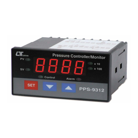
3. FRONT PANEL DESCRIPTION Fig. 1 3-1 Display 3-2 PV ( process value ) indicator 3-3 SV ( set value ) indicator 3-4 Set Button Button ▼ Button ▲ 3-7 Control relay indicator 3-8 Alarm relay indicator 3-9 X10 indicator 3-10 X100 indicator 3-11 Wire terminals 3-12 Case holder... -
Page 9: Measuring Procedure
4. MEASURING PROCEDURE 4-1 Terminal connection 1) Input the ACV power ( 90 to 260 ACV ) to T1, T2. Do not input the over voltage to the AC input terminals. 2) Connect the " Control Relay " output from T3, T4. Connect the "... -
Page 10: 1St Layer Setting Procedures
2) Make the wires installation as following : 3) Select the sensor type, please refer Chapter 4-2, page 10. Select the sensor unit, please refer Chapter 4-2, page 14. 4-3 1st layer setting procedures CtLo Control low value setting CtHi Control high value setting ALLo Alarm low value setting... - Page 11 Control low value setting 1) Press the " Set Button " ( 3-4, Fig. 1 ) once, the " Display " will show " CtLo ", now the meter is ready for the " Control low value " setting. 2) Use the " Button "...
-
Page 12: 2Nd Layer Setting Procedures
2) Use the " Button " ( 3-5, Fig. 1 ) and the " ▼ ▲ Button " ( 3-6, Fig. 1 ) to adjust the desiring " Alarm low value ". Remark : * When adjust the value, the " SV indicator " ( 3-3, Fig. 1 ) will light. - Page 13 Sensor type setting 1) Press the " Set Button " ( 3-4, Fig. 1 ) continuously at least two seconds, the " Display " will show " tyPE ", now the meter is ready for the " Sensor type " setting. 2) Use the "...
- Page 14 Control Hysteresis value setting 1) After finish the " Digital filter setting ", press the " Set Button " ( 3-4, Fig. 1 ) once, the " Display " will show CtHy ", now the meter is ready for the " Control Hysteresis value "...
- Page 15 Alarm Hysteresis value setting 1) After select the " Control Hysteresis value " , press the " Set Button " ( 3-4, Fig. 1 ) twice, the " Display " will show " ALHy ", now the meter is ready for the the "...
- Page 16 Offset value adjustment 1) After finish the " Alarm hysteresis value setting " , press the " Set Button " ( 3-4, Fig. 1 ) twice, the " Display " will show " oFSt ", now the meter is ready for the " Offset value adjustment "...
-
Page 17: Rs232 Pc Serial Interface
Unit setting 1) After finish the " Gain value setting " , press the " Set Button " ( 3-4, Fig. 1 ) once, the " Display " will show " Unit ", now the meter is ready for the the " Unit setting " 2) Use the "... - Page 18 A RS232 lead with the following connection will be required to link the instrument with the PC serial port. Meter (9W 'D" Connector) (3.5 mm jack plug) Center Pin........ Pin 4 Ground/shield......Pin 2 Pin 5 The 16 digits data stream will be displayed in the following format : D15 D14 D13 D12 D11 D10 D9 D8 D7 D6 D5 D4 D3 D2 D1 D0 Each digit indicates the following status :...
-
Page 19: System Reset
D8 to D1 Display reading, D8 = MSD, D1 = LSD. For example : If the display reading is 1234, then D8 to D1 is : 00001234 End Word RS232 setting Baud rate 9600 Parity No parity Data bit no. 8 Data bits Stop bit 1 Stop bit... -
Page 20: The Address Of After Service Center
* Allow high cable load resistance, transmitter can install far away from the controller/indicator. * Protection for the reverse wires connecting. * TR-PS2W can cooperate the " Pressure controller/monitor, PPS-9312 or the " 4-20 mA Controller/Alarm/Indicator CT-2012 ". 8. THE ADDRESS OF AFTER SERVICE CENTER...
Need help?
Do you have a question about the PPS-9312 and is the answer not in the manual?
Questions and answers