Sign In
Upload
Download
Table of Contents
Contents
Add to my manuals
Delete from my manuals
Share
URL of this page:
HTML Link:
Bookmark this page
Add
Manual will be automatically added to "My Manuals"
Print this page
×
Bookmark added
×
Added to my manuals
Manuals
Brands
Mastech Manuals
Multimeter
MY70
Operation manual
Mastech MY70 Operation Manual
Hide thumbs
1
Table Of Contents
2
3
4
5
6
7
8
9
10
11
12
13
14
page
of
14
Go
/
14
Contents
Table of Contents
Bookmarks
Table of Contents
Table of Contents
1 General Instructions
Safety Information
Safety Instructions
Safe Working Habits
Safety Symbols
Safe Maintenance Habits
Input Protection Measures
2 Meter Appearance Description
Meter Appearance
LCD Display
Input Socket
3 Operating Guidance
General Operation
Reading Maintenance Mode
Measuring Guidance
Measuring AC and DC Voltage
Measuring Resistance
Testing Diode
Audible Continuity Testing
Measuring Capacitance (MY74,MY74B)
Transistor Measuring
Measuring Frequency (MY74,MY74B)
Measuring Temperature (MY74,MY74B)
Measuring Current
4 Technical Indicators
Comprehensive Indicators
Accuracy Indicators
DC Voltage
AC Voltage
Frequency (Only for MY74,MY74B)
Resistance
Diode
Audible Continuity
Transistor
Capacitance (Only for MY74,MY74B)
Temperature (Only for MY74,MY74B)
DC Current
AC Current
5 Meter Maintenance
General Maintenance
Replace Battery and Fuse
Replacing Test Leads
Cleaning and Decontamination
6 Accessories
Advertisement
Quick Links
1
Measuring Ac and DC Voltage
2
Replace Battery and Fuse
Download this manual
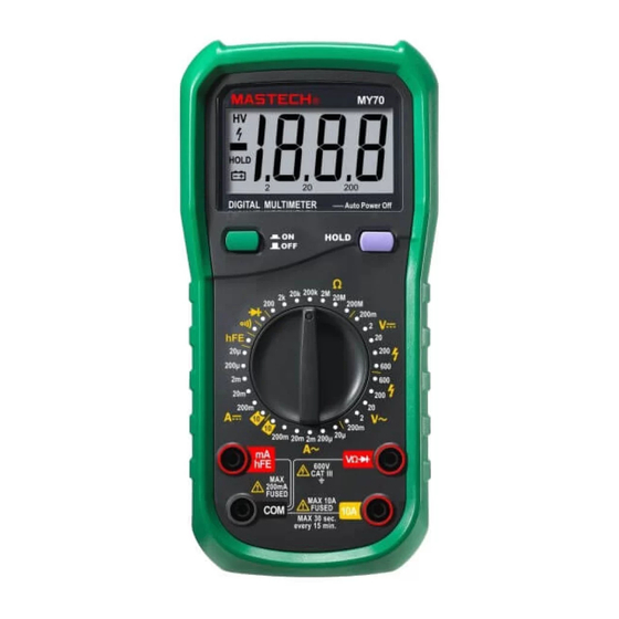
MY70/74/74B
DIGITAL MULTIMETER
OPERATION MANUAL
CAT III
600V
Table of
Contents
Previous
Page
Next
Page
1
2
3
4
5
Advertisement
Table of Contents
Need help?
Do you have a question about the MY70 and is the answer not in the manual?
Ask a question
Questions and answers
Related Manuals for Mastech MY70
Multimeter Mastech MY-60 Operator's Manual
My-60 series digital multimeter (17 pages)
Multimeter Mastech MY60 Manual
(16 pages)
Multimeter Mastech MY64 Manual
(9 pages)
Multimeter Mastech my68 Instruction Manual
Handheld digital multimeter (16 pages)
Multimeter Mastech MY-68 User Manual
(6 pages)
Multimeter Mastech MY-65 User Manual
(6 pages)
Multimeter Mastech MY65 Operator's Manual
(9 pages)
Multimeter Mastech MY67 Instruction Manual
(16 pages)
Multimeter Mastech MY74 Operation Manual
(14 pages)
Multimeter Mastech MS8268 Instruction Manual
Handheld digital multimeter (18 pages)
Multimeter Mastech MS8268 Operator's Instruction Manual
Handheld digital multimeter (9 pages)
Multimeter Mastech MAS830B Operator's Instruction Manual
(11 pages)
Multimeter Mastech MS8264 Operator's Instruction Manual
Handheld digital multimeter (16 pages)
Multimeter Mastech MS8321A Manual
(9 pages)
Multimeter Mastech MS8229 Operation Manual
(25 pages)
Multimeter Mastech MS8361D User Manual
(14 pages)
This manual is also suitable for:
My74
My74b
Table of Contents
Print
Rename the bookmark
Delete bookmark?
Delete from my manuals?
Login
Sign In
OR
Sign in with Facebook
Sign in with Google
Upload manual
Upload from disk
Upload from URL


Need help?
Do you have a question about the MY70 and is the answer not in the manual?
Questions and answers