
Related Manuals for Mastech MY-60


Summary of Contents for Mastech MY-60
- Page 1 OPERATOR’S MANUAL DIGITAL MULTIMETER ⊙ MY-60 ⊙ MY-60T ⊙ MY-61 ⊙ MY-62 ⊙ MY-63 ⊙ MY-64 ○ ○...
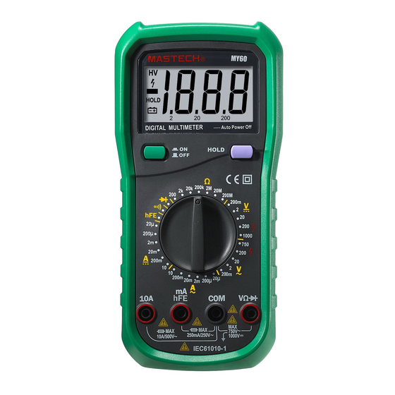
- Page 2 INTRODUCTION This MY-60 Series Digital Multimeter is a compact precision, battery operated, LCD display 3-½ digits Digital Instrument. Superiority: High accuracy Large LCD display Digital height 25mm Single 32 position rotary switch for FUNCTION and RANGE selection, allows fast and convenient operation.
- Page 3 A ccu racy R an ge M Y -60 M Y -6 0T M Y -61 M Y -6 2 M Y -63 M Y -64 0.5% ± 1 2 00m V 0.5% ± 2 2 0V 200 V 0.8% ± 2 10 00V Input impedance: 10MΩ...
- Page 4 A ccu racy R an ge M Y -60 M Y -6 0T M Y -61 M Y -6 2 M Y -63 M Y -64 1 .0 % ± 10 200 Ω 2K Ω 20 K Ω 1.0% ± 3 2 00K Ω...
- Page 5 5.2 DCA & ACA MEASUREMENT Connect the black test lead to the “COM” terminal and the red test lead to “A” terminal for a maximum of 0.5A (model MY-60 & MY-60T maximum Set the function range switch at the required position.
- Page 6 Excessive current will below the fuse that must be replaced when the input is from “A” terminal. Fuse type is 0.5A (model MY-60 & MY-60T maximum 2A). A fuse does not protect the 10A range. Maximum 8A continuous, maximum 10A measuring time must be less than 15 seconds.
- Page 7 read the display value. Note: The tested capacitor should be discharged before the testing procedure. Never apply voltage to the “Cx” input socket, or serious damage may result. 5.5 FREQUENCY MEASUREMENT Set the function range switch at the required “Hz” position. Connect test leads to measuring points and read the display value.
- Page 8 Dress the battery leads so that they will not be pinched between the case bottom can case top. The meter is protected fast fuse 0.5A/250V (model MY-60 & MY-60T protected fuse 2A/250V), dimensions is Φ5*20mm.
-
Page 9: Table Of Contents
OPERATOR’S MANUAL CAUTION: * Before attempting to insert transistors capacitor thermocouple for testing, always be sure that test lest leads have been disconnected from any measurement circuits. * Components should not be connected to the hFE and capacitor and the thermocouple socket when making voltage measure with test leads. -
Page 10: Safety Information
1. SAFETY INFORMATIONS This multimeter has been designed according to IEC-1010 concerning electronic measuring instruments with an overvoltage category (CATⅡ) and pollution 2. Follow all safety and operating instructions to ensure that meter is used safely and is kept in good operating condition. -
Page 11: Maintenance
MAINTENANCE * Before opening the meter, always disconnect test leads from all sources of electric current. * For continue protection against fire, replace fuse only with the specified and current rating: F200mA / 250V (quick acting) *If any faults or abnormalities are observed, the meter can not be used any more and it has to be checked out. -
Page 12: Operating Instruction
FUNCTION AND RANGE SELECTOR There are different functions and 32 ranges provided. A rotary switch is used to select functions as well as ranges. POWER SWITCH A push-push switch is used to turn the meter on or off. To extend the battery life, Auto Power- Off function is provided (Optional). The meter will be turned off automatically within around 40 minutes. -
Page 13: Measuring Frequency
The polarity of the red lead connection will be indicated along with the current value when making DC current measurement. 3. When only the figure”1” displayed, it indicates overrange situation and the higher range has to be selected. 3.3 MEASURING FREQUECY 1. -
Page 14: Testing Diode
3.6 TESTING DIODE 1. Connect the black test lead to COM jack and the red test lead to the VΩHz jack (The polarity of red lead is〝+〞) 2. Set the rotary switch at position and connect red lead to the anode, black lead to the cathode of the diode under testing .The meter will show the approx. - Page 15 “ ”appears on the display LOW BATTERY INDICATION 31.5mm×91mm×189mm SIZE (HxWxL) 310g(including battery) WEIGHT 4.2 DC VOLTAGE Range Resolution Accuracy ±0.5% of rdg ± 1 digit 200mV 0.1mv ±0.5% of rdg ± 1 digit ±0.5% of rdg ± 1 digit 10mV ±0.5% of rdg ±...
-
Page 16: Accessories
4.6 RESISTANCE Range Resolution Accuracy ±0.8% of rdg ± 3 digits 200Ω 0.1Ω ±0.8% of rdg ± 1 digit 2KΩ 1Ω ±0.8% of rdg ± 1 digit 20KΩ 10Ω ±0.8% of rdg ± 1 digit 200KΩ 100Ω ±0.8% of rdg ± 1 digit 2MΩ... -
Page 17: How To Use The Holster
For protection against fire, replace fuse only with specified ratings: F 200mA/250V (quick acting). -26- PRECISION MASTECH ENTERPRISES CO. Room 1708-09, Hewlett Centre, 54 Hoi Yuen Road,Kwun Tong, Kowloon, Hong Kong. Tel:852-23430007 Fax:852-23436217 E-mail:info@p-mastech.com...
Need help?
Do you have a question about the MY-60 and is the answer not in the manual?
Questions and answers