Advertisement
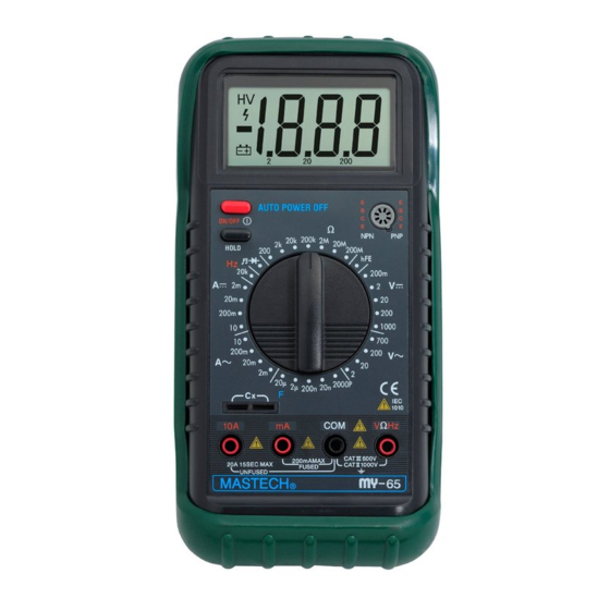
MY-65 4 1/2-DIGIT DIGITAL MULTIMETER
Read the Users Manual thoroughly before use.
WARRANTY
This instrument is warranted to be free from defects in material and workmanship for a period of
one year. Any instrument found defective within one year from the delivery date and returned to
the factory with transportation charges prepaid, will be repaired, adjusted, or replaced at no charge
to the original purchaser. This warranty does not cover expandable items such as batteries or fuses.
If the defect has been caused by a misuse or abnormal operating conditions, the repair will be
billed at a nominal cost.
SAFETY INFORMATION
UT30B digital multimeter has been designed according to IEC-1010 concerning electronic
measuring instruments with an overvoltage category (CATⅡ) and pollution2.
Full compliance with safety standards can be guaranteed only with test leads supplied. If necessary,
they must be replaced with the type specified in the manual.
ELECTRICAL SYMBOLS
AC (Alternating Current)
DC (Direct Current)
Important safety information. Refer to the manual.
Dangerous voltage may be present.
Earth ground
Fuse
Conforms to European Union directives
Double insulated
WARNING
To avoid possible electric shock or personal injury, follow these guidelines:
l
Do not use the meter if it is damaged. Before you use the meter, inspect the case. Pay
particular attention to the insulation surrounding the connectors
l
Inspect the test leads for damaged insulation or exposed metal. Check the test leads for
continuity. Replace damaged test leads before you use the meter.
l
Do not use the meter if it operates abnormally. Protection may be impaired. When in doubt,
have the meter serviced.
l
Do not operate the meter around explosive gas, vapor, or dust.
l
Do not apply more than the rated voltage, as marked on the meter, between terminals or
between any terminal and earth ground.
l
Before use, verify the meter's operation by measuring a known voltage.
l
When servicing the meter, use only specified replacement parts.
l
Use with caution when working above 30V ac rms, 42V peak, or 60V dc. Such voltages pose
a shock hazard.
l
When using the probes, keep your fingers behind the finger guards on the probes.
l
Connect the common test lead before you connect the live test lead. When you disconnect
test leads, disconnect the live test lead first.
Users Manual
Advertisement
Table of Contents

Subscribe to Our Youtube Channel
Related Manuals for Mastech MY-65


Summary of Contents for Mastech MY-65
- Page 1 MY-65 4 1/2-DIGIT DIGITAL MULTIMETER Users Manual Read the Users Manual thoroughly before use. WARRANTY This instrument is warranted to be free from defects in material and workmanship for a period of one year. Any instrument found defective within one year from the delivery date and returned to the factory with transportation charges prepaid, will be repaired, adjusted, or replaced at no charge to the original purchaser.
-
Page 2: Maintenance
INTRODUCTION MY-65 Digital Multimeter is a handheld 4 1/2-digit LCD digital multimeter with the advantages of precision reading and stable performance etc., and can be used for the measurement of DC voltage, AC voltage, DC current, AC current, resistance, capacitance, diode, frequency and continuity. It is an ideal instrument for use in the field, laboratory, workshop, and home. -
Page 3: Specifications
Auto power-off Operating temperature: 0℃~50℃ Storage temperature: -40℃~60℃ Low battery indication: symbol “ ” displayed on the upper left of the LCD. Dimensions: 70(W)×155(L)×39(H)mm Weight: approx. 250g SPECIFICATIONS Accuracy is specified for a period of one year after calibration and at 18℃~28℃ with relative humidity to 75%. -
Page 4: Audible Continuity
±(1.2%+10) 200mA 10µA ±(2.5%+10) Overload protection: 250mA/250V fused (range 10A unfused) Max. input current: 10A (Can not last for more than 10 seconds.) Frequency: 40Hz~1000Hz Indication: Average (rms of sine wave) RESISTANCE Range Resolution Accuracy ±(0.5%+10) 200Ω 0.01Ω ±(0.3%+5) 2KΩ 0.1Ω... - Page 5 or load to be measured. 3. When only the figure “1” is displayed on the LCD, it indicates that the voltage under measurement is over-range and the rotary switch must be set to higher range. MEASURING CURRENT 1. Connect the black test lead to the “COM” jack and the red test lead to the “mA” jack for the current up to 200mA or to the “A”...
-
Page 6: Continuity Test
2. Determine whether the transistor to be tested is NPN or PNP, and locate the E, B and C leads. Insert the leads of the transistor into their proper holes of the transistor testing socket. 3. The meter will show the approx. hFE value at the test condition of Ib≈10μA and Vce≈ 3.2V.
Need help?
Do you have a question about the MY-65 and is the answer not in the manual?
Questions and answers