Table of Contents
Advertisement
Quick Links
Download this manual
See also:
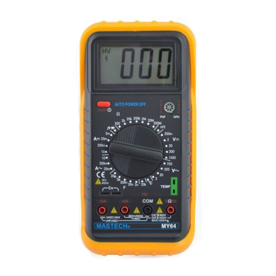
Operator's Manual
When the user exceeds the current capacity of the MY64 multimeter, an internal fuse opens to protect
the precision current shunt. Typically this occurs when the user leaves the multimeter in current
measuring mode and places the probes across a voltage source.
Page 26 of the MY64 Operator's Manual instructs the user to:
• Disconnect the test leads
• Remove the screws on the back cover and open the case
• Take the PCB out from the front cover
• Replace the blown fuse with the same ratings
The above explanation leaves out a few details, which may frustrate a user. Here are some instructions
with pictures to help you be successful.
WARNING! Static discharge can destroy your meter. The ECE department will not be responsible for
meter abuse. If you have any doubts about your ability to perform this procedure, consult with a
Teaching Assistant in the Computer Engineering Labs.
After removing the test leads, separate the meter from the yellow bumper, using your fingers to peel
from the top.
Turn the meter on its face on a soft surface. Unscrew the 3 identical screws with a #2 Phillips
screwdriver. The screws have a right-hand thread, so turn the screwdriver counter-clockwise.
CAUTION! Using a screwdriver that is too small or too large may permanently damage the meter case
screws. It is not necessary to remove the screws, but you may have less difficulty with the next step if
you do.
Changing the Fuse in the MY64 Multimeter
15 September 2005, by Bob Lineberry, Page 1
Advertisement
Table of Contents

Related Manuals for Mastech MY64


Summary of Contents for Mastech MY64
- Page 1 Changing the Fuse in the MY64 Multimeter When the user exceeds the current capacity of the MY64 multimeter, an internal fuse opens to protect the precision current shunt. Typically this occurs when the user leaves the multimeter in current measuring mode and places the probes across a voltage source.
- Page 2 Changing the Fuse in the MY64 Multimeter Lift up on the bottom end of the case (with 2 screws). The top of the case snaps on and off. Guide the case back straight up from the meter, being careful not to bend any internal parts.
- Page 3 Changing the Fuse in the MY64 Multimeter Carefully lift the battery and connector out of the battery compartment. Notice the routing of the battery cable through the case slot. Remove the battery. Lift the circuit board straight up, using both hands. Continue working on a soft surface.
- Page 4 Changing the Fuse in the MY64 Multimeter Each ECE2004/3004 kit comes with 5 spare 200 mA fuses. WARNING! These fuses have a glass body, which can break and cut you. Which is cheaper: a fuse with a higher current rating, or a new meter? Turn the circuit board over on the soft surface.
- Page 5 Changing the Fuse in the MY64 Multimeter Using both hands, gently guide the board back into the case. Be careful not to force the board or bend any components. When the board is in place, the level of the board will match the level of the battery holder. You may also turn the meter over to check for jack and switch alignment.
- Page 6 Changing the Fuse in the MY64 Multimeter Install the 9 volt battery, aligning pins to sockets. Using a meter probe, guide the battery wires into the case slot. Note the relative location of the black insulation on the battery wires.
- Page 7 Changing the Fuse in the MY64 Multimeter Start the 3 identical case screws by hand. If you encounter resistance, reverse the screw direction until there is no resistance and start again. The screws are going into plastic. You do not want to cut new threads.
- Page 8 Changing the Fuse in the MY64 Multimeter Finish tightening the case screws. CAUTION! Don’t over tighten metal screws into a plastic case or you may permanently damage your meter. Maneuver the meter into the bottom of the yellow bumper. Snap the meter top into the yellow bumper.
Need help?
Do you have a question about the MY64 and is the answer not in the manual?
Questions and answers