Advertisement
TM
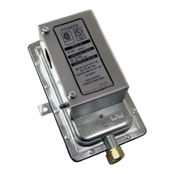
Powers
SW 141 Differential Static
Airflow Switches
Description
Application
Product Numbers
*
Setpoint accuracy tolerance and switching differential decrease proportional to setpoint decrease.
Controls
The SW 141 Airflow Switch senses static differential pressure and the diaphragm operated
snap switches actuate electrical circuits. Auto reset and manual reset models are
available.
Auto reset switches (141-0518 and 141-0574) should be used for applications requiring
positive proof of airflow (or fan operation) or to detect high differential pressures
associated with dirty air filters or similar maintenance alarms not requiring safety lock-out
(shut down) of the fan.
The manual reset switch (141-0575) should be used for applications requiring safety lock
out (shut down) of the fan. The switch can be used on the fan discharge (positive
pressure), fan inlet (negative pressure), or across the fan (differential pressure) to detect
excessively high positive pressures or low negative pressures, and turn off the fan before
damage occurs to ducts or dampers.
Product
Setpoint Range
Number
(Field Adjustable)
141-
1" to 12" WC
0518
(250 Pa to 3000 Pa)
141-
1" to 12" WC
0575
(250 Pa to 3000 Pa)
141-
0.05" to 1.0" WC
0574
(12.5 Pa to 250 Pa)
Technical Instructions
Document No. 155-052P25
141-0518
Table 1.
Setpoint *
Accuracy
@ 12" ± 1.5" WC
(3000 Pa ± 375 Pa)
0.6" to 1.5" WC
(150 Pa to 375 Pa)
@ 12" ± 1.5" WC
Not Applicable
(3000 Pa ± 375 Pa)
@ 1"±0.2" WC
(250 Pa ± 50 Pa)
0.06" to 0.6" WC
(15 Pa to 150 Pa)
SW 141-1
June 17, 2010
Switching *
Switching
Differential
Action
Approx.
SPDT/
Auto Reset
SPST/
Manual
Reset
Approx.
SPDT/
Auto Reset
Siemens Industry, Inc.
Advertisement
Table of Contents

Related Manuals for Siemens Powers SW 141 Series


Summary of Contents for Siemens Powers SW 141 Series
- Page 1 @ 1”±0.2“ WC Approx. SPDT/ (250 Pa ± 50 Pa) 0574 (12.5 Pa to 250 Pa) Auto Reset 0.06" to 0.6” WC (15 Pa to 150 Pa) Setpoint accuracy tolerance and switching differential decrease proportional to setpoint decrease. Siemens Industry, Inc.
-
Page 2: Specifications
Installation Mount the unit with the diaphragm in any vertical plane. Connect the static pressure line(s) as shown in Figure 1. Switch Nut & Integral Ferrule Tubing Figure 1. Connecting the Static Pressure Line. Page 2 Siemens Industry, Inc. - Page 3 2. Adjust the setpoint until switching occurs at the required point. 3. Check the setpoint for accuracy with a magnahelic gauge. The Red Band Is " The Setpoint Location On The Scale 12.0 Figure 3. Adjusting the Setpoint. Siemens Industry, Inc. Page 3...
-
Page 4: Pressure Sensors
Figure 5. Manual Reset Switch 141-0575. Figure 6. Auto Reset Switches 141-0518 and 141-0574. SPDT terminals are marked Common (C), Normally Open (NO), and Normally Closed (NC). Figure 7. Auto Reset Switches to Prove Excessive Airflow or Pressure. Page 4 Siemens Industry, Inc. - Page 5 Information in this publication is based on current specifications. The company reserves the right to make changes in specifications and models as design improvements are introduced. Powers is a registered trademark of Siemens Industry, Inc. Other product or company names mentioned herein may be the trademarks of their respective owners.
Need help?
Do you have a question about the Powers SW 141 Series and is the answer not in the manual?
Questions and answers