Siemens SCALANCE XM-400 Operating Instructions Manual
Simatic net industrial ethernet switches
Hide thumbs
Also See for SCALANCE XM-400:
- Configuration manual (960 pages) ,
- Instructions manual (60 pages) ,
- Configuration manual (610 pages)
Table of Contents
Advertisement
Quick Links
SCALANCE XM-400
SIMATIC NET
Industrial Ethernet switches
SCALANCE XM-400
Operating Instructions
05/2014
C79000-G8976-C306-03
___________________
Introduction
___________________
Safety notices
___________________
Description of the device
___________________
Installation
___________________
Connecting up
___________________
Upkeep and maintenance
___________________
Technical specifications
___________________
Dimension drawings
___________________
Approvals
1
2
3
4
5
6
7
A
Advertisement
Table of Contents

Related Manuals for Siemens SCALANCE XM-400


Summary of Contents for Siemens SCALANCE XM-400
- Page 1 ___________________ SCALANCE XM-400 Introduction ___________________ Safety notices ___________________ Description of the device SIMATIC NET ___________________ Installation Industrial Ethernet switches ___________________ SCALANCE XM-400 Connecting up ___________________ Upkeep and maintenance Operating Instructions ___________________ Technical specifications ___________________ Dimension drawings ___________________ Approvals 05/2014 C79000-G8976-C306-03...
- Page 2 Note the following: WARNING Siemens products may only be used for the applications described in the catalog and in the relevant technical documentation. If products and components from other manufacturers are used, these must be recommended or approved by Siemens. Proper transport, storage, installation, assembly, commissioning, operation and maintenance are required to ensure that the products operate safely and without any problems.
-
Page 3: Introduction
● SCALANCE XM408-4C ● SCALANCE XM408-8C ● SCALANCE XM416-4C Unless mentioned otherwise, the descriptions in these operating instructions refer to all devices of the SCALANCE XM-400 product group named above in the section on validity. Designations used Classification Description Terms used Product line The product line includes all devices and variants of all product groups. - Page 4 ● On the data medium that ships with some products: – Product CD / product DVD – SIMATIC NET Manual Collection ● On the Internet pages of Siemens Industry Online Support under the following entry IDs: – 27069465 (http://support.automation.siemens.com/WW/view/en/27069465) Industrial Ethernet / PROFINET Industrial Ethernet System Manual –...
- Page 5 ● On the Internet under the following entry ID: 50305045 (http://support.automation.siemens.com/WW/view/en/50305045) Catalogs You will find the order numbers for the Siemens products of relevance here in the following catalogs: ● SIMATIC NET Industrial Communication / Industrial Identification, catalog IK PI ●...
- Page 6 Siemens recommends strongly that you regularly check for product updates. For the secure operation of Siemens products and solutions, it is necessary to take suitable preventive action (e.g. cell protection concept) and integrate each component into a holistic, state-of-the-art industrial security concept.
-
Page 7: Table Of Contents
Mounting on DIN rails ........................37 Installation on a standard S7-300 rail ..................39 Installation on a standard S7-1500 rail ..................40 Fitting an extender ........................41 General notes for SFP transceivers ..................... 44 SCALANCE XM-400 Operating Instructions, 05/2014, C79000-G8976-C306-03... - Page 8 Technical specifications of the SCALANCE XM408-8C ............. 61 Technical specifications of the SCALANCE XM416-4C ............. 63 Switching properties ........................65 Dimension drawings ..........................67 SCALANCE XM-400 dimension drawings .................. 67 Extender dimension drawings ..................... 70 Approvals ..............................73 FDA and IEC marks ........................77 Mechanical stability (in operation) ....................
-
Page 9: Safety Notices
This equipment is suitable for use in Class I, Division 2, Groups A, B, C and D or non- hazardous locations only. This equipment is suitable for use in Class I, Zone 2, Group IIC or non-hazardous locations only. SCALANCE XM-400 Operating Instructions, 05/2014, C79000-G8976-C306-03... - Page 10 Safety notices SCALANCE XM-400 Operating Instructions, 05/2014, C79000-G8976-C306-03...
-
Page 11: Description Of The Device
(10/100/1000 Mbps) and SFP transceiver slots that can be equipped individually. The SFP transceiver slots are combo ports. A SCALANCE XM-400 can manage a maximum of 24 ports with 10/100/1000 Mbps. The following components exist only on the basic device: ●... -
Page 12: Product Overview
16 RJ-45 ports, 4 pluggable transceiver slots, max. 1 port 6GK5 416-4GR00-2AM2 extender, layer 3 integrated Type designation The type designation of a SCALANCE XM-400 is made up of several parts that have the following meaning: SCALANCE XM-400 Operating Instructions, 05/2014, C79000-G8976-C306-03... - Page 13 SCALANCE XM408-8C SCALANCE XM416-4C Components of the product The following components are supplied with a SCALANCE XM-400: ● One device with exchangeable storage medium C-PLUG ● One product DVD with documentation and software ● Securing screw for mounting on an S7 standard rail ●...
-
Page 14: Accessories
Description of the device 2.3 Accessories Accessories The following accessories are available for SCALANCE XM-400: KEY-PLUG Type Order number KEY-PLUG XM400 Layer 3 6GK5 904-0PA00 SFP transceiver Type Property Order number SFP991-1 1 x 100 Mbps, LC port optical for glass FO cable 6GK5 991-1AD00-8AA0 (multimode), up to max. - Page 15 Port extender Device Property Order number PE408 8 x 10/100/1000 Mbps RJ-45 ports 6GK5 408-0GA00-8AP2 PE408PoE 8 x 10/100/1000 Mbps, RJ-45 ports with PoE 6GK5 408-0PA00-8AP2 PE400-8SFP 8 x 100/1000 Mbps, SFP ports 6GK5 400-8AS00-8AP2 SCALANCE XM-400 Operating Instructions, 05/2014, C79000-G8976-C306-03...
-
Page 16: Spare Parts
Description of the device 2.4 Spare parts Spare parts The following spare parts are available for SCALANCE XM-400: Component Description Order number C-PLUG Configuration plug, 6GK1 900-0AB00 exchangeable storage medium for configuration data Spring-loaded terminal block, 4-terminal spring-loaded terminal block to connect the... -
Page 17: Views
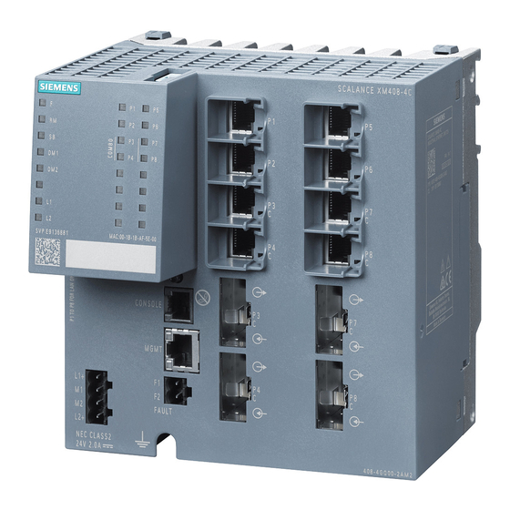
Electrical ports ② Expansion interface with cover ③ Slots for pluggable transceivers (STP and DCP) ④ Location for securing to an S7 standard rail ⑤ Grounding ⑥ LED display ⑦ Slots for C-PLUG / KEY-PLUG SCALANCE XM-400 Operating Instructions, 05/2014, C79000-G8976-C306-03... -
Page 18: View Of A Scalance Xm408-8C Device
The following figure shows an overview of the components of the SCALANCE XM408-8C. ① Electrical ports ② Expansion interface with cover ③ Slots for SFP transceivers ④ Location for securing to an S7 standard rail ⑤ Grounding ⑥ LED display ⑦ Slots for C-PLUG / KEY-PLUG SCALANCE XM-400 Operating Instructions, 05/2014, C79000-G8976-C306-03... -
Page 19: View Of A Scalance Xm416-4C Device
The following figure shows an overview of the components of the SCALANCE XM416-4C. ① Electrical ports ② Expansion interface with cover ③ Slots for SFP transceivers ④ Location for securing to an S7 standard rail ⑤ Grounding ⑥ LED display ⑦ Slots for C-PLUG / KEY-PLUG SCALANCE XM-400 Operating Instructions, 05/2014, C79000-G8976-C306-03... -
Page 20: Select / Set Button
Description of the device 2.6 SELECT / SET button SELECT / SET button Position The "SELECT/SET" button is located on the front of the SCALANCE XM-400. Figure 2-1 Position of the "SELECT/SET" button on the SCALANCE XM-400 Setting the display mode To set the required display mode, press the "SELECT/SET"... - Page 21 After you have held down the button for 5 seconds, the current settings are stored as the "good status". If you release the button before the 5 seconds have elapsed, the previous fault mask will be retained. SCALANCE XM-400 Operating Instructions, 05/2014, C79000-G8976-C306-03...
- Page 22 The redundancy manager and media redundancy are disabled. Result: After enabling the redundancy manager, media redundancy is also enabled. – Initial situation: The redundancy manager and media redundancy are enabled. Result: After disabling the redundancy manager, media redundancy remains enabled. SCALANCE XM-400 Operating Instructions, 05/2014, C79000-G8976-C306-03...
-
Page 23: Led Display
The device is a redundancy manager. The ring is working without problems, monitoring is activated. Green Flashing The device is a redundancy manager. An interruption has been detected on the ring and the device has switched through. SCALANCE XM-400 Operating Instructions, 05/2014, C79000-G8976-C306-03... -
Page 24: Sb" Led
There are errors in the firmware. Meaning during operation LED color LED status Meaning during operation The device is operating free of errors. The device has detected a problem. The signaling contact has opened. SCALANCE XM-400 Operating Instructions, 05/2014, C79000-G8976-C306-03... -
Page 25: Leds "Dm1" And "Dm2
LED status Display mode starting at display mode A Display mode A Press once Display mode B Press twice Display mode C Press three times Display mode D Press four times Flashing Display mode E SCALANCE XM-400 Operating Instructions, 05/2014, C79000-G8976-C306-03... -
Page 26: Leds "L1" And "L2
Power supply is not monitored. If the power supply falls below 17 V, the signaling contact does not respond. Green Power supply is monitored. If the power supply falls below 17 V, the signaling contact responds. SCALANCE XM-400 Operating Instructions, 05/2014, C79000-G8976-C306-03... -
Page 27: Port Leds
LED goes off. Meaning in display mode C In display mode C, the port LEDs indicate the mode. LED color LED status Meaning Port operating in half duplex mode Green Port operating in full duplex mode SCALANCE XM-400 Operating Instructions, 05/2014, C79000-G8976-C306-03... - Page 28 In display mode E, the port LEDs indicate whether the connected device is supplied using PoE. LED color LED status Meaning The connected device is not supplied using PoE. Green The connected device is supplied via PoE. SCALANCE XM-400 Operating Instructions, 05/2014, C79000-G8976-C306-03...
-
Page 29: C-Plug/Key-Plug
A device with a written and accepted C-PLUG/KEY-PLUG ("ACCEPTED" status) automatically uses its configuration data during startup. Acceptance is only possible if the data was written by a compatible device type. This mode is active as soon as a written C-PLUG/KEY-PLUG is inserted. SCALANCE XM-400 Operating Instructions, 05/2014, C79000-G8976-C306-03... -
Page 30: Replacing The C-Plug/Key-Plug
If it is detected that the C-PLUG/KEY-PLUG was removed, there is a restart. If a KEY-PLUG was inserted in the device, the device changes to a defined error state following the restart. The C-PLUG/KEY-PLUG slot is on the top of the device housing. SCALANCE XM-400 Operating Instructions, 05/2014, C79000-G8976-C306-03... - Page 31 1. Turn off the power to the device. 2. The housing of the C-PLUG/KEY-PLUG has a protruding ridge on the long side (B). The slot has a groove at this position. Insert the C-PLUG/KEY-PLUG into the slot correctly aligned. SCALANCE XM-400 Operating Instructions, 05/2014, C79000-G8976-C306-03...
-
Page 32: Functions
The pluggable transceiver port is used independent of the fixed RJ-45 port. The factory setting for the combo ports is mode 1: auto. You configure the mode with Web Based Management or the Command Line Interface. SCALANCE XM-400 Operating Instructions, 05/2014, C79000-G8976-C306-03... -
Page 33: Power Over Ethernet (Poe)
These are supplied with power via the Ethernet cable. Power over Ethernet with SCALANCE XM-400 With a SCALANCE XM-400, you can use the "Power over Ethernet" function via the port extender PE408PoE as the power generator. You will find detailed information on the port extender PE408PoE in the operating instructions "Extenders for SCALANCE XM-400". - Page 34 Description of the device 2.9 Functions SCALANCE XM-400 Operating Instructions, 05/2014, C79000-G8976-C306-03...
-
Page 35: Installation
WARNING To comply with EU Directive 94/9 (ATEX95), this enclosure must meet the requirements of at least IP54 in compliance with EN 60529. SCALANCE XM-400 Operating Instructions, 05/2014, C79000-G8976-C306-03... - Page 36 "Industrial Ethernet / PROFINET Industrial Ethernet" and "Industrial Ethernet / PROFINET passive network components". You will find information on the system manuals in the section "Introduction (Page 3)", in "Further documentation". SCALANCE XM-400 Operating Instructions, 05/2014, C79000-G8976-C306-03...
-
Page 37: Types Of Installation
(> 10 g). When used under these conditions, the device can detach itself and may cause injury to persons. When used in shipbuilding or when extreme vibration can be expected, mount the device on a S7 standard rail. Figure 3-1 DIN rail mounting SCALANCE XM-400 Operating Instructions, 05/2014, C79000-G8976-C306-03... - Page 38 To remove the device from a DIN rail, follow the steps below: 1. Disconnect all connected cables. 2. Release the DIN rail catch on the bottom of the device using a screwdriver. 3. Pull lower part of the device away from the DIN rail. SCALANCE XM-400 Operating Instructions, 05/2014, C79000-G8976-C306-03...
-
Page 39: Installation On A Standard S7-300 Rail
To remove the device from a standard rail, follow the steps below: 1. Disconnect all connected cables. 2. Release the screw on the bottom of the standard rail. 3. Remove the device from the standard rail. SCALANCE XM-400 Operating Instructions, 05/2014, C79000-G8976-C306-03... -
Page 40: Installation On A Standard S7-1500 Rail
To remove the device from a standard rail, follow the steps below: 1. Disconnect all connected cables. 2. Release the screw on the bottom of the standard rail. 3. Remove the device from the standard rail. SCALANCE XM-400 Operating Instructions, 05/2014, C79000-G8976-C306-03... -
Page 41: Fitting An Extender
● You can mount a device on a DIN or S7 standard rail and expand it later. Note For mounting on a rail as well as for removing from the rail, plan enough space between the devices, see section "Extender dimension drawings (Page 70)". SCALANCE XM-400 Operating Instructions, 05/2014, C79000-G8976-C306-03... - Page 42 1. Release the locking device using a screwdriver The two devices are separated from each other. ② 2. Pull the two devices apart in a straight line until the two centering pins are completely out of the openings. SCALANCE XM-400 Operating Instructions, 05/2014, C79000-G8976-C306-03...
- Page 43 ● The event is shown in the log table in WBM. Enabling the extender To activate the replacement extender, restart the IE switch: ● The extender is active. ● The red fault LED "F" goes off. SCALANCE XM-400 Operating Instructions, 05/2014, C79000-G8976-C306-03...
-
Page 44: General Notes For Sfp Transceivers
WARNING Use only approved SFP transceivers If you use SFP transceivers that have not been approved by Siemens AG, there is no guarantee that the device will function according to its specifications. If you use unapproved SFP transceivers, this can lead to the following problems: •... -
Page 45: Connecting Up
If you use the device under HazLoc conditions you must also keep to the following safety notices in addition to the general safety notices for protection against explosion: WARNING EXPLOSION HAZARD DO NOT DISCONNECT WHILE CIRCUIT IS LIVE UNLESS AREA IS KNOWN TO BE NON-HAZARDOUS. SCALANCE XM-400 Operating Instructions, 05/2014, C79000-G8976-C306-03... - Page 46 The LAN is considered to be in an "environment A" according to IEEE802.3 or "environment 0" according to IEC TR 62102, respectively. Never connect directly to TNV-circuits (Telephone Network) or WAN (Wide Area Network). SCALANCE XM-400 Operating Instructions, 05/2014, C79000-G8976-C306-03...
-
Page 47: Spring-Loaded Terminal
Dehn Blitzductor BVT AVD 24, article number 918 422 or a comparable protective element. Manufacturer: DEHN+SOEHNE GmbH+Co.KG, Hans-Dehn-Str.1, Postfach 1640, D92306 Neumarkt, Germany Operate the SCALANCE XM-400 with suitable overvoltage protection. Note The port extenders PE400 and SFP transceivers are supplied with power via the basic device. - Page 48 ● To wire up the power connector, use a copper cable of category 18-12 AWG or cable with a cross-section of 0.75 to 2.5 mm². Position and assignment Figure 4-1 Position of the power supply on the SCALANCE XM-400 and the assignment of the terminal block Contact Assignment...
-
Page 49: Signaling Contact
The signaling contact can be subjected to a maximum load of 100 mA (safety extra-low voltage SELV, 24 VDC). Higher voltages or currents can damage the device! Position and assignment Figure 4-2 Position of the signaling contact on the SCALANCE XM-400 and the assignment of the terminal block Pin number Assignment Pin 1... - Page 50 ● The signaling contact remains open until one of the following events occurs: – The problem is eliminated. – The current status is entered in the fault mask as the new desired status. SCALANCE XM-400 Operating Instructions, 05/2014, C79000-G8976-C306-03...
-
Page 51: Serial Interface
The supplied connecting cable has the following assignment: Contact Pin assignment of the RJ-11 plug Pin assignment of the D-sub female connector TD (Transmit Data) TD (Transmit Data) RD (Receive Data) SG (Signal Ground) RD (Receive Data) SG (Signal Ground) SCALANCE XM-400 Operating Instructions, 05/2014, C79000-G8976-C306-03... - Page 52 Connecting up 4.5 Serial interface Note Pin assignment of the RJ-11 jack on the device The RJ-11 jack on the device has a pinout to match the RJ-11 plug of the supplied connecting cable. SCALANCE XM-400 Operating Instructions, 05/2014, C79000-G8976-C306-03...
-
Page 53: Out-Of-Band Interface
● Access to the device is also possible independent of the other Ethernet ports. ● The out-of-band interface allows direct IP access to the WBM of the device. Position and assignment Figure 4-4 Position and pin assignment of the out-of-band interface (RJ-45 jack) on the SCALANCE XM-400. SCALANCE XM-400 Operating Instructions, 05/2014, C79000-G8976-C306-03... -
Page 54: Near Field Communication
Position of Near Field Communication on the SCALANCE XM-400 Reading out information To read out information via the SCALANCE XM-400 using NFC, follow the steps below: 1. Turn on Near Field Communication on the SCALANCE XM-400. As default the function is turned off. -
Page 55: Functional Ground
The functional ground is established via a grounding screw. The connector for the grounding cable is in the center of the underside of the device. Figure 4-6 Position of the grounding bolt on the SCALANCE XM-400 Connecting up functional ground ①... - Page 56 Connecting up 4.8 Functional ground SCALANCE XM-400 Operating Instructions, 05/2014, C79000-G8976-C306-03...
-
Page 57: Upkeep And Maintenance
Upkeep and maintenance Downloading new firmware using TFTP without WBM and CLI Firmware The firmware is signed and encrypted. This ensures that only firmware created by Siemens can be downloaded to the device. Procedure with Microsoft Windows Using TFTP, you can supply a device with new firmware even when it cannot be reached using WBM or CLI. -
Page 58: Restoring The Factory Settings
3. Hold down the button until the red fault LED "F" stops flashing after approximately 40 seconds and is permanently lit. 4. Now release the button and wait until the fault LED "F" goes off again. 5. The device starts automatically with the factory settings. SCALANCE XM-400 Operating Instructions, 05/2014, C79000-G8976-C306-03... -
Page 59: Technical Specifications
24 V DC 0.6 A Effective power loss at 24 V DC 48 W 14.4 W Signaling contact Quantity Design Terminal block, 2 terminals Permitted voltage range 24 VDC Load capability max. 100 mA SCALANCE XM-400 Operating Instructions, 05/2014, C79000-G8976-C306-03... - Page 60 Installation options Installation on a DIN rail • Installation on an S7-300 standard rail • Installation on an S7-1500 standard rail • Mean time between failure (MTBF) at 40 °C ambient temperature 28 years SCALANCE XM-400 Operating Instructions, 05/2014, C79000-G8976-C306-03...
-
Page 61: Technical Specifications Of The Scalance Xm408-8C
During operation up to 3000 m -40 ℃ to +65 ℃ During storage -40 ℃ to +85 ℃ During transportation -40 ℃ to +85 ℃ Relative humidity During operation at 25 ℃ ≤ 95%, no condensation SCALANCE XM-400 Operating Instructions, 05/2014, C79000-G8976-C306-03... - Page 62 Installation options Installation on a DIN rail • Installation on an S7-300 standard rail • Installation on an S7-1500 standard rail • Mean time between failure (MTBF) at 40 °C ambient temperature 28 years SCALANCE XM-400 Operating Instructions, 05/2014, C79000-G8976-C306-03...
-
Page 63: Technical Specifications Of The Scalance Xm416-4C
During operation up to 3000 m -40 ℃ to +65 ℃ During storage -40 ℃ to +85 ℃ During transportation -40 ℃ to +85 ℃ Relative humidity During operation at 25 ℃ ≤ 95%, no condensation SCALANCE XM-400 Operating Instructions, 05/2014, C79000-G8976-C306-03... - Page 64 Installation options Installation on a DIN rail • Installation on an S7-300 standard rail • Installation on an S7-1500 standard rail • Mean time between failure (MTBF) at 40 °C ambient temperature 22 years SCALANCE XM-400 Operating Instructions, 05/2014, C79000-G8976-C306-03...
-
Page 65: Switching Properties
1518 bytes Note The number of SCALANCE XM-400 modules connected in a line influences the frame delay. When a frame passes through the switch, this is delayed by the store-and-forward function of the SCALANCE XM-400 by 25-70 microseconds (at 1000 Mbps). - Page 66 Technical specifications 6.4 Switching properties SCALANCE XM-400 Operating Instructions, 05/2014, C79000-G8976-C306-03...
-
Page 67: Dimension Drawings
Dimension drawings SCALANCE XM-400 dimension drawings Note Dimensions are specified in mm. Front view SCALANCE XM-400 Operating Instructions, 05/2014, C79000-G8976-C306-03... - Page 68 Dimension drawings 7.1 SCALANCE XM-400 dimension drawings Side view SCALANCE XM-400 Operating Instructions, 05/2014, C79000-G8976-C306-03...
- Page 69 Dimension drawings 7.1 SCALANCE XM-400 dimension drawings From above SCALANCE XM-400 Operating Instructions, 05/2014, C79000-G8976-C306-03...
-
Page 70: Extender Dimension Drawings
Dimension drawings 7.2 Extender dimension drawings Extender dimension drawings Note Installing on a rail Remember the following dimensions if you want to mount two devices on a rail. Front view SCALANCE XM-400 Operating Instructions, 05/2014, C79000-G8976-C306-03... - Page 71 Dimension drawings 7.2 Extender dimension drawings From above SCALANCE XM-400 Operating Instructions, 05/2014, C79000-G8976-C306-03...
- Page 72 Dimension drawings 7.2 Extender dimension drawings SCALANCE XM-400 Operating Instructions, 05/2014, C79000-G8976-C306-03...
-
Page 73: Approvals
The installation of expansions that are not approved for SIMATIC NET products or their target systems may violate the requirements and regulations for safety and electromagnetic compatibility. Only use expansions that are approved for the system. SCALANCE XM-400 Operating Instructions, 05/2014, C79000-G8976-C306-03... - Page 74 Safety of electrical equipment In the version put into circulation by Siemens AG, the SIMATIC NET products described in these Operating Instructions conform to the regulations of the following European directive: ●...
- Page 75 Area". You will find this document • on the data medium that ships with some devices. • on the Internet pages of Siemens Industry Online Support (http://support.automation.siemens.com/WW/view/en). Enter the document identification number C234 as the search term. SIMATIC NET products meet the requirements of the EC directive:94/9/EC "Equipment and Protective Devices for Use in Potentially Explosive Atmospheres".
- Page 76 Cl. 1, Zone 2, GP IIC T4 Report no. E240480 EU declaration of conformity You will find EC declaration of conformity for these products on the Internet pages of Siemens Industry Online Support (http://support.automation.siemens.com/WW/view/en/33118389/134200). SCALANCE XM-400 Operating Instructions, 05/2014, C79000-G8976-C306-03...
-
Page 77: Fda And Iec Marks
1 octave/min, 20 sweeps 1 octave/min, 20 sweeps SCALANCE XM408-4C ● ● ● SCALANCE XM408-8C ● ● ● SCALANCE XM416-4C ● ● ● * Note: When installing on an S7-300 or S7-1500 standard rail SCALANCE XM-400 Operating Instructions, 05/2014, C79000-G8976-C306-03... - Page 78 Approvals A.2 Mechanical stability (in operation) SCALANCE XM-400 Operating Instructions, 05/2014, C79000-G8976-C306-03...
-
Page 79: Index
Functional ground, 55 PoE, 33, 41 Port extender PE408PoE, 33, 41 Port extender, 12 Port extender PE408PoE, 33, 41 Power over Ethernet, 33, 41 Glossary, 5 Port extender PE408PoE, 33, 41 Grounding, 17, 19, 55 SCALANCE XM-400 Operating Instructions, 05/2014, C79000-G8976-C306-03... -
Page 80: Scalance Xm
Spare parts, 16 Spring-loaded terminal, 13, 16, 47, 48, 49 Startup phase, 21, 24, 58 STP transceiver, 15, 17 System manual, 4, 36, 74 WBM, 3, 30, 53, 57 Web Based Management, 3, 30, 53, 57 SCALANCE XM-400 Operating Instructions, 05/2014, C79000-G8976-C306-03...
Need help?
Do you have a question about the SCALANCE XM-400 and is the answer not in the manual?
Questions and answers