Table of Contents
Advertisement
Quick Links
Curiosity PIC32MZ EF 2.0 Development Board Users Guide
Introduction
The Microchip Technology Curiosity PIC32MZ EF 2.0 Development Board (DM320209) includes an integrated
programmer and debugger, which requires no additional hardware to get started. Users can expand functionality
through MikroElectronika mikroBUS
Daughter Board, add Wi-Fi
output capability with Microchip audio daughter boards.
With or without expansion boards, the Curiosity PIC32MZ EF 2.0 Development Board provides the freedom to
develop a variety of applications, including Bluetooth Audio, CAN, Graphics/UI, Internet of Things (IoT), robotics
development, and proof-of-concept designs.
Curiosity PIC32MZ EF 2.0 Development Board Features
The Curiosity PIC32MZ EF 2.0 Development Board has the following features:
•
PIC32MZ2048EFM144, 200 MHz, 2 MB Flash, 512 Kb SRAM
•
On-Board debugger (PKoB4)
– Real time Programming & Debugging
– Virtual COM port (VCOM)
– Data Gateway Interface (DGI)
•
Two mikroBUS interfaces
•
Two X32 Audio interfaces supporting Bluetooth
•
Ethernet interface
•
Graphics interface
•
Xplained pro extension compatible interface
•
CAN interface
•
User buttons
•
User LEDs
•
8 MB QSPI memory
•
Arduino Uno R3 compatible interface
Kit Contents
The kit contains one Curiosity PIC32MZ EF 2.0 Development Board (DM320209).
Note: If any part is missing from the kit, contact a Microchip sales office for assistance. A list of Microchip offices for
sales and service is provided on the last page of this document.
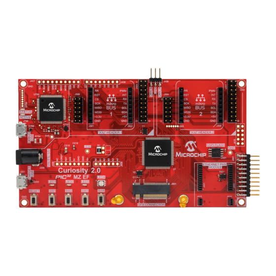
Curiosity PIC32MZ EF 2.0 Development Board
The Curiosity PIC32MZ EF 2.0 Development Board (DM320209) is shown in the following figure:
©
2019 Microchip Technology Inc.
™
™
Click
adapter boards, add Ethernet connectivity with the Microchip PHY
®
connectivity capability using the Microchip expansions boards, and add audio input and
®
and Audio
DS70005400A-page 1
Advertisement
Table of Contents

Subscribe to Our Youtube Channel
Related Manuals for Microchip Technology Curiosity PIC32MZ EF 2.0


Summary of Contents for Microchip Technology Curiosity PIC32MZ EF 2.0
-
Page 1: Introduction
Microchip expansions boards, and add audio input and output capability with Microchip audio daughter boards. With or without expansion boards, the Curiosity PIC32MZ EF 2.0 Development Board provides the freedom to develop a variety of applications, including Bluetooth Audio, CAN, Graphics/UI, Internet of Things (IoT), robotics development, and proof-of-concept designs. - Page 2 DS70005400A-page 2 © 2019 Microchip Technology Inc.
-
Page 3: Table Of Contents
Table of Contents Introduction..............................1 Curiosity PIC32MZ EF 2.0 Development Board Features............1 Kit Contents..........................1 Curiosity PIC32MZ EF 2.0 Development Board ..................1 Development Board Functionality and Features..................4 1.1. Board Feature Location........................4 1.2. System Block Diagram......................... 5 1.3. Power Block Diagram........................5 1.4. -
Page 4: Development Board Functionality And Features
Development Board Functionality and Features Development Board Functionality and Features Board Feature Location Figure 1-1. Curiosity PIC32MZ EF 2.0 Development Board Layout (Top View) Table 1-1. Board Features and Locations Number Description of Item PICKit on Board 4 (PKoB4) Arduino Uno interface. Headers not populated mikroBUS Click interface. -
Page 5: System Block Diagram
The following figure shows a block diagram of the power system on the Curiosity PIC32MZ EF 2.0 Development Board. The Curiosity PIC32MZ EF 2.0 Development Board has several power sub systems that allow it to accept up to 16V. The barrel jack is a 2.1 mm center positive connector. The power in can also be connected through the Arduino header, this input is before the reverse voltage protection. -
Page 6: Pickit On-Board 4
Field-upgradeable through an MPLAB X IDE firmware download • Adds new device support and features by installing the latest version of MPLAB X IDE (available as a free download at https://www.microchip.com/mplabx/) • Indicates debugger status through on-board LEDs DS70005400A-page 6 © 2019 Microchip Technology Inc. - Page 7 PICkit On-Board 4 is not responding, the user can recover the it by following these steps: With the Curiosity PIC32MZ EF 2.0 Development Board is still powered, short the two pads for approximately 10 seconds. Figure 1-4. Location of Pads to Short BOTTOM of Board...
-
Page 8: I 2 C Voltage Selection
0 ohm or a bus bar must be installed. A 0805 SMD footprint has been provided. This is located on the back side of the board. The following figure shows the I C jumper in the trace: DS70005400A-page 8 © 2019 Microchip Technology Inc. - Page 9 Development Board Functionality and Features Figure 1-6. I C Jumper The following figure shows the schematic representation: Figure 1-7. Schematic Representation DS70005400A-page 9 © 2019 Microchip Technology Inc.
-
Page 10: X32 Audio Interface
S and other control lines, and data interfaces. 1.6.1 Block Diagram The Curiosity PIC32MZ EF 2.0 Development Board has two X32 interfaces that share two I S signals. The following figure shows the relation between the I S signals and the X32 daughter board interface. - Page 11 X32 Interface Block Diagram additional information. Table 1-3. Port Connections Interface X32#1 X32#2 UART RX RPC4 RPE9 UART TX RPC1 RPG9 DS70005400A-page 11 © 2019 Microchip Technology Inc.
-
Page 12: Mikrobus
The following table provides the port connections to the mikroBUS interface. The mikroBUS is nested inside of the X32 Audio interface. Due to mechanical interference, either a mikroBUS or Audio interface can be used in the same DS70005400A-page 12 © 2019 Microchip Technology Inc. -
Page 13: Control Area Network (Can) Bus Interface
Control Area Network (CAN) Bus Interface The Curiosity PIC32MZ EF 2.0 Development Board provides access to a CAN interface that is post transceiver. The on-board CAN transceiver is an ATA6561, which allows the application to be used directly with any CAN bus compliant interface. - Page 14 General purpose I/O RH12 EGND Shield Ground 13 (1) TXEN Transmit Enable 14 (2) TXD0 Transmit Data 15 (3) TDX1 Transmit Data 16 (4) MOSI Master Out Slave In line of serial peripheral interface. DS70005400A-page 14 © 2019 Microchip Technology Inc.
-
Page 15: Xplained Pro Extension Standard Header
Xplained Pro Extension Standard Header The Curiosity PIC32MZ EF 2.0 Development Board has an Xplained Pro extension compatible interface that enables using the existing extension boards. This interface consists of a dual row, 20-pin, 100 mil, 90 degree extension male header. -
Page 16: Graphics Connector/Gfx Card Interface
Power for extension boards (3.3V) Figure 1-10. Pinout Schematic 1.11 Graphics Connector/GFX Card Interface The Curiosity PIC32MZ EF 2.0 Development Board has a new graphics interface that enables using different graphics cards to support different graphics models. Table 1-9. Graphics Pinout Pin Number... - Page 17 Implemented on this design) LCD D9 LCD Data bit 9 LCD PWM LCD PWM back light control RPB6/OC1 LCD D10 LCD Data bit 10 PWM2 Pulse width modulation, RPD15 LCD D11 LCD Data bit 11 DS70005400A-page 17 © 2019 Microchip Technology Inc.
- Page 18 ADC to MCU (Not implemented on this design) No Connect 3.3V VCC +3.3V VCC ADC7 ADC to MCU (Not implemented on this design) No Connect Ground 3.3V VCC +3.3V VCC Ground GND TAB Mounting Tab GND TAB Mounting Tab DS70005400A-page 18 © 2019 Microchip Technology Inc.
-
Page 19: Buttons And Leds
For host device class operation, a USB OTG cable is needed. To enable power from the Curiosity PIC32MZ EF 2.0 Development Board, the user must control the VBUS Enable pin. The Curiosity PIC32MZ EF 2.0 Development Board must be powered through an external source, Vin, PKoB4, or barrel jack. -
Page 20: Hardware
Hardware Hardware Schematics DS70005400A-page 20 © 2019 Microchip Technology Inc. - Page 21 Hardware DS70005400A-page 21 © 2019 Microchip Technology Inc.
- Page 22 Hardware 2 4 6 8 10 DS70005400A-page 22 © 2019 Microchip Technology Inc.
- Page 23 Hardware 2 4 6 8 10 12 2 4 6 8 10 12 2 4 6 8 10 12 14 16 2 4 6 8 10 12 14 16 DS70005400A-page 23 © 2019 Microchip Technology Inc.
- Page 24 Hardware 2 4 6 8 10 12 14 16 DS70005400A-page 24 © 2019 Microchip Technology Inc.
- Page 25 Hardware DS70005400A-page 25 © 2019 Microchip Technology Inc.
- Page 26 Hardware DS70005400A-page 26 © 2019 Microchip Technology Inc.
- Page 27 Hardware MikroBUS 1 AUDIO 1 MikroBUS 2 AUDIO 2 DS70005400A-page 27 © 2019 Microchip Technology Inc.
- Page 28 Hardware DS70005400A-page 28 © 2019 Microchip Technology Inc.
- Page 29 Hardware DS70005400A-page 29 © 2019 Microchip Technology Inc.
- Page 30 Hardware DS70005400A-page 30 © 2019 Microchip Technology Inc.
- Page 31 Hardware DS70005400A-page 31 © 2019 Microchip Technology Inc.
- Page 32 Hardware DS70005400A-page 32 © 2019 Microchip Technology Inc.
- Page 33 Hardware DS70005400A-page 33 © 2019 Microchip Technology Inc.
- Page 34 Hardware DS70005400A-page 34 © 2019 Microchip Technology Inc.
- Page 35 Hardware DS70005400A-page 35 © 2019 Microchip Technology Inc.
-
Page 36: Bill Of Materials
RES TKF 0R 1/3W SMD 1210 R6, R7, R8, R9 RES TKF 1.8k 1% 1/10W SMD 0402 R200, R201, R403, R503, R504, R505, R506, R507, R601, R703, R704, RES TKF 10k 1% 1/10W SMD 0402 R708, R727 DS70005400A-page 36 © 2019 Microchip Technology Inc. - Page 37 Y401 MCHP CLOCK OSCILLATOR 50MHz DSC1001CI2-050.0000T DFN-4 PAD1, PAD2, PAD3, PAD4 MECH HW RUBBER PAD CYLINDRICAL D9.53H5.97 J701 CON HDR-1.27 Female 1x8 TH VERT CON HDR-2.54 Male 1X2 Gold 6mm MH TH R/A DS70005400A-page 37 © 2019 Microchip Technology Inc.
-
Page 38: Board Dimensions
RES TKF 0R 1/16W SMD 0805 R731, R732, R733, R734 RES TKF 4.7k 1% 1/16W SMD 0402 DAT_EN, ERASE, MH1, MH2, MH3, MH4, RX1, TP1, TP2, TP3V3, TX1, Non-populated Test Points Board Dimensions DS70005400A-page 38 © 2019 Microchip Technology Inc. -
Page 39: The Microchip Web Site
Attempts to break Microchip’s code protection feature may be a violation of the Digital Millennium Copyright Act. If such acts allow unauthorized access to your software or other copyrighted work, you may have a right to sue for relief under that Act. DS70005400A-page 39 © 2019 Microchip Technology Inc. -
Page 40: Legal Notice
SQTP is a service mark of Microchip Technology Incorporated in the U.S.A. Silicon Storage Technology is a registered trademark of Microchip Technology Inc. in other countries. GestIC is a registered trademark of Microchip Technology Germany II GmbH & Co. KG, a subsidiary of Microchip Technology Inc., in other countries. -
Page 41: Worldwide Sales And Service
Tel: 46-31-704-60-40 New York, NY Sweden - Stockholm Tel: 631-435-6000 Tel: 46-8-5090-4654 San Jose, CA UK - Wokingham Tel: 408-735-9110 Tel: 44-118-921-5800 Tel: 408-436-4270 Fax: 44-118-921-5820 Canada - Toronto Tel: 905-695-1980 Fax: 905-695-2078 DS70005400A-page 41 © 2019 Microchip Technology Inc.
Need help?
Do you have a question about the Curiosity PIC32MZ EF 2.0 and is the answer not in the manual?
Questions and answers