Table of Contents
Advertisement
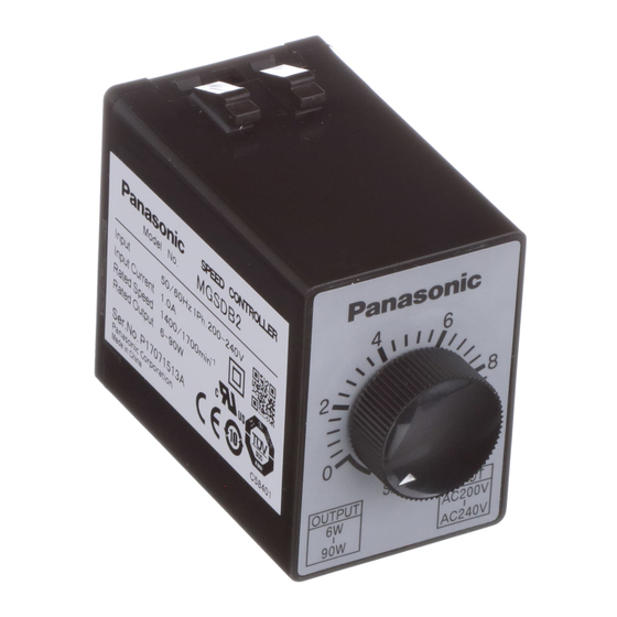
Speed Controller for Small Geared Motors
• Thank you for purchasing the Panasonic speed controller
MGSD for small geared motor.
• Carefully read this manual thoroughly before installing and
operating the product.
Section "Safety Precautions" (pp. 3-9) contains very
important information concerning safety and reliable
operation.
Keep this manual in a safe location where it can be easily
accessed for reference.
The user and operator should always refer to this manual.
This product is for industrial equipment.Don't use this product
at general household.
Instruction Manual
MGSD Series
Advertisement
Table of Contents

Related Manuals for Panasonic MGSDB2


Summary of Contents for Panasonic MGSDB2
- Page 1 Instruction Manual Speed Controller for Small Geared Motors MGSD Series • Thank you for purchasing the Panasonic speed controller MGSD for small geared motor. • Carefully read this manual thoroughly before installing and operating the product. Section "Safety Precautions" (pp. 3-9) contains very important information concerning safety and reliable operation.
-
Page 2: Table Of Contents
Safety Precautions Please observe safety precautions fully. • Contents Please strictly observe safety precautions described below to prevent personal injury and property damage. page Safety Precautions ............3 ■ The below explains what will happen if someone fails to 1. Introduction ..............10 heed a particular precaution statement. -
Page 3: Safety Precautions
Safety Precautions Please observe safety precautions fully. Danger Use overcurrent protection device, ground-fault circuit interrupter, Failure to heed overtemperature protecting device, these requirements and emergency stop device. will result in electric Don't use the speed controller in shock, personal or near environment containing After an earthquake, first verify injury or fire. - Page 4 Safety Precautions Please observe safety precautions fully. Locked motor will Failure to heed this Don't lock the motor shaft while Install the equipment in the cause fire, electric the motor is running. precaution will result in control board and keep the shock, or malfunction.
- Page 5 Safety Precautions Please observe safety precautions fully. Perform installation by taking into consideration the mass of the Don't place any obstacle object Temperature rise will body and rated output of the around the motor and peripheral, cause burn injury or product.
-
Page 6: Introduction
Series the distribution board, and small timer common option available from 1. Single phase 100 – 120 VAC Output Panasonic Corporation (pp. 32 – 37). 2. Single phase 200 – 240 VAC 3 – 40 W 100 V B : 60 – 90 W... - Page 7 G : 220 – 230 V M6RX**GBV4** M7RX***V4** Version M71X***V4** AC200 V Blank : Pinion shaft motor (Japanese standard) M7RX**GBV4** : Round shaft motor (Japanese standard) MGSDB2 6-90 W M8RX***V4** : International standard approved motor (CE, UL, CCC) M81X***V4** AC240 V M8RX**GBV4** M9RX***V4** M91X***V4**...
-
Page 8: Names And Functions
2. Names and functions 3. Installation Installation location Terminal block locking Terminal block hook mounting hole locking claw (1) Indoors free from rain and direct sunlight: the product is not of a waterproof construction. Nameplate (2) Free from vibration 4.9 m/s or more;... -
Page 9: Wiring Diagram
3. Installation 4. Wiring diagram Considerations for wiring Installing method The product can be mounted in either of the following two ways but • Use a terminal block or socket for connection. Do not solder the must be installed inside the control board. lead to the pin. -
Page 10: Wiring Diagram
AT7803: • The thick continuous lines represent main circuit. Use conductor Panasonic of size 0.75 mm (AWG 18) or larger for the main line. See Section 6. • The thin continuous lines represent signal circuit. Use conductor References. -
Page 11: Standard Electrical Wiring Diagram
CCW Counterclockwise ON. When configuring SW2 with relay contacts, use a relay having large gap interchange the connecting point of black between contacts (e.g. HL relay: Panasonic) to prevent malfunction due to and gray leads. short-circuited capacitor. – 20 –... -
Page 12: Unidirectional Rotation And Electric Brake
4. Wiring diagram Unidirectional rotation and electric brake 40 W or higher <Precautions> Feed motor • The number of start/stop operations should be 6/min. or less. rated voltage External 25 W or less braking Gray resistor STOP Feed motor rated voltage Black Motor Capacitor... -
Page 13: Normal/Reverse Rotation And Electric Brake
4. Wiring diagram Normal/reverse rotation and electric brake 40 W or higher <Precautions> Feed motor • The number of start/stop operations should be 6/min. or less. rated voltage External 25 W or less braking resistor Gray STOP Feed motor rated voltage Black Motor Capacitor... -
Page 14: Peripheral Wiring
4. Wiring diagram Peripheral wiring Wiring to electromagnetic brake (40 W or below) Variable speed motor with electromagnetic brake should be wired as Motor wiring with cooling fan motor (F) or thermal protector (TP) shown below. The thermal protector (TP) is an automatic reset type. To prevent hazards caused by restarting of TP, operate it by connecting wiring as Feed motor shown below. -
Page 15: Options
5. Options <Note> Tachometer (DV0P001) Calibrate the scale of the tachometer (TM) from the potentiometer on This tachometer is especially designed to operate with our speed the rear panel. controller so that it can provide easier displaying of motor speed. 1. - Page 16 C1 = 0.1 – 0.33 μ F (AC250 WV) 41 ±1 Noise filter (DV0P3611-5) Type SUP-EQ5-ER-6: Okaya Electric Industries Co., Ltd. Octal pin socket (DV0P4560) Unit: mm 100.0 ±2.0 Type AW68102: Panasonic 88.0 Terminal cover (clear) 75.0 53.1 ±1.0 Unit: mm (7.5)
-
Page 17: References
Unit: mm 4–ø4.5 Marking (label) 3.6 x 4.8 • To prevent contact failure Option common to compact timers: Panasonic and loose connection, positively engage the locking The following common timer option is available through your local Locking hook hooks. agent for Panasonic. - Page 18 6. References Flush mounting frame: Panasonic Part No. Control board mounting Color Mounting hole dimensions (unit: mm) ordered surface, front view AT7851 Gray R2 or below +0.5 50.5 AT7852 Black type Distance between parallel holes AT7853 Silver gray 6.5 mm or more +0.5...
- Page 19 6. References (3) Engage the hook with the base to fix it to the mounting frame. Installing Hook (1) Insert the mounting frame from the front panel of the cutout. [Note] 8P cap As the body touches the mounting frame rib, push upper and lower hooks in the direction of arrow for locking.
-
Page 20: Compatible With International Standards
Electrical high speed transient burst immunity test Panasonic Testing Centre IEC61000-4-5 Panasonic Service Europe, Lightning surge immunity test a division of Panasonic Marketing Europe GmbH Winsbergring 15,22525 Hamburg,F.R.Germany IEC61000-4-6 High-frequency conductivity immunity test IEC61000-4-11 Instantaneous power interruption immunity test – 38 –... - Page 21 Speed controller and peripherals East Japan : 03-3515-9151 NEC Tokin Corporation West Japan : 06-6263-6781 Product Option part No. Manufacturer part No. Manufacturer Panasonic Corporation 0120-101-550 Noise filter MR-2043 NEC Tokin Corp. Sensata Technologies, Inc. 049-283-7575 Okaya Electric Surge absorber DV0P4190 R.A.V-781BWZ-4...
-
Page 22: Specification
8. Specification General specification Dimensions • Speed controller MGSDA1 MGSDB1 MGSDB2 Part No. ø1 200 VAC Power source ø1 100 VAC – 120 VAC Unit: mm – 240 VAC Supply voltage permissible Rated voltage ±10 % variable range Power supply frequency... -
Page 23: Inspection And Maintenance
9. Inspection and maintenance Inspection Troubleshooting Periodically check and maintenance to assure safe and reliable If a problem occurs with your system, use the following procedure for operation of the speed controller. locating and remove the cause. In the event the problem cannot be isolated or the speed controller Practical considerations for checking and maintenance is suspected, or if you have any questions, please contact us or your Turning off/on of power supply must be done by the personnel... -
Page 24: After-Sale Service (Repair)
After-Sale Service (Repair) MEMO Repair Consult to a dealer from whom you have purchased the product for details of repair. When the product is incorporated to the machine or equipment you have purchased, consult to the manufacuter or the dealer of the machine or equipment. - Page 25 MEMO (Fill in the blanks for reference in case of inquiry or repair.) Date of Model No. MGSD purchase Dealer Tel: ( Panasonic Corporation, Appliances Company, Motor Business Division 7-1-1 Morofuku, Daito, Osaka, 574-0044, Japan Phone : +81-72-871-1212 © Panasonic Corporation 2014 IMD98...
Need help?
Do you have a question about the MGSDB2 and is the answer not in the manual?
Questions and answers