Advertisement
Quick Links
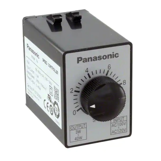
Speed Controller Overview
Overview of Speed Controllers
• These controllers vary speed of compact geared motors.
• The lineup of the speed controllers is divided into the following 4 types to meet various applications and configuration.
1. Separate type speed controller
2. 48 mm sq. (1.89 inch sq.) speed controller
3. Unit type speed controller
4. Inverter
Product designation
• Separate type speed controller
• MGSD type
MGSD B
2
Output Input power
1 : Single phase 100 to 120 VAC
2 : Single phase 200 to 240 VAC
A
100 V
60 to 90 W
B
200 V
Series
• EX type
DV 11
31
Voltage
Code
11 : 100 V
12 : 200 V
Speed controller
C-2
Speed controller of the basic configuration
Separate speed controller housed in 48 mm sq. (1.89 inch sq.)
DIN size
A set of a motor and speed controller: Both can be connected
through a single-touch connector.
Speed controller for 3-phase motor
3 to 40 W
6 to 90 W
Compatible motor output
Code
Type
100 V
200 V
31
3 to 10 W
6 to 20 W
32
EX
15 to 40 W
–
34
60 to 90 W
25 to 90 W
• 48 mm sq. (1.89 inch sq.) speed controller
DV SD 48 A
L
Voltage
Code Output Voltage
48 mm sq.
(1.89 inch sq.)
SD : Potentiometer
EX : High-performance
A : 3 to 20 W
B : 25 to 40 W
Speed controller
C : 60 to 90 W
• Unit type speed controller
MUSN
8
25
G
Size
Output Shape of shaft
6 : 60 mm sq.
6 : 6 W
(2.36 inch sq.)
15 : 15 W
7 : 70 mm sq.
25 : 25 W
(2.76 inch sq.)
40 : 40 W
8 : 80 mm sq.
60 : 60 W
(3.15 inch sq.)
90 : 90 W
MUSN : US series
9 : 90 mm sq.
MUXN : UX series
(3.54 inch sq.)
• Inverter
M1G
4A
1
V1X
Motor output Voltage
Shape
Series
Power system
1 : Single phase AC100 to 110 V 50/60 Hz
2 : Single phase AC200 to 230 V 50/60 Hz
Compatible motor output
4A : 25 W, 40 W
9A : 60 W, 90 W
L : 100 to 120 V
Y : 200 to 240 V
L
Toothed
L : 100 V
Y : 200 V
Toothed
With control
C-3
Advertisement

Related Manuals for Panasonic MGSD


Summary of Contents for Panasonic MGSD
- Page 1 B : 25 to 40 W Speed controller C : 60 to 90 W Product designation • Separate type speed controller • Unit type speed controller • MGSD type MUSN MGSD B Size Output Shape of shaft Toothed Output Input power...
- Page 2 DV1131 DVSD48AL DVEX48AL * When using a speed controller operative under a wide range of supply voltage (MGSD, SD48, EX48), the mating motor should be selected (2.36 inch sq. according to the voltage of the power supply to be used.
- Page 3 • Outline drawing controlling systems such as sequencer. The voltage signal can also be used as control signal. EX type 93.5(3.68) 14.2(0.56) • Standard specification (MGSD type) MGSDA1 MGSDB1 MGSDB2 Supply voltage Single phase 100 to 120 VAC Single phase 200 to 240 VAC ±10% (at rated voltage)
- Page 4 Speed controller MGSD type • Connection diagram list Speed change only Connection diagram Function Speed controller Page Wiring diagram (for unidirectional rotation) MGSD type C- 8 Rotating direction viewed Unidirectional rotation Speed change only MGSD type C- 9 from shaft end...
- Page 5 Speed controller MGSD type Unidirectional rotation and electric brake Normal/reverse rotation and electric brake • Connection according to this wiring Rotating direction viewed 25 W or smaller 25 W or smaller diagram causes the motor to rotate from shaft end...
-
Page 6: Speed Controller
Speed controller Speed controller MGSD type EX type Wiring of cooling fan motor (F) or motor with thermal protector (TP) Wiring diagram (for unidirectional rotation) • The thick continuous lines represent main circuit. Use conductor of size 0.75 mm or larger for the main line. - Page 7 Speed controller EX type Speed change only Unidirectional rotation and electric brake • Connection according to this wiring Unidirectional rotation Normal/reverse rotation 25 W or smaller diagram causes the motor to rotate Rated voltage clockwise when viewed from the Rated voltage Rated voltage input motor shaft end.
- Page 8 Speed controller EX type Normal/reverse rotation and electric brake Multispeed setting application 25 W or smaller No braking applied Braking applied STOP SW3 Rated voltage input Rotating direction viewed SW3, SW8 DC10V 10 mA from shaft end Clockwise DV0P002 White Counterclockwise (option) STOP...
- Page 9 Speed controller EX type Operation through contactless signal Parallel operation through analog signal • Small signal relays SW3, SW6 and SW7 can be replaced with transistor. <Precautions> 0 to +3 V The input impedance of the controller is approx. 100 kΩ. The output impedance of the analog signal source No braking applied Braking applied...
- Page 10 –20 to 60˚C –20 to 60˚C “Start/stop control with small signal”. *1. Applicable to Panasonic compact geared motors and variable speed motors. *2. EX48 models are set to mode A (high-stable) upon shipment. *3. Electric braking has no mechanical brake holding force.
- Page 11 Speed controller Speed controller 48 mm sq. (1.89 inchsq.) type SD48 type • Outline drawing Wiring diagram (for unidirectional rotation) 48 mm sq. SD48 type • The motor revolving speed can be set from the speed setting knob on the panel. •...
- Page 12 Speed controller SD48 type Speed change only Unidirectional rotation and electric brake Rotating direction viewed Unidirectional rotation 25 W or smaller from shaft end • Connection according to this wiring diagram causes the motor to rotate Clockwise Rated voltage Rated voltage clockwise when viewed from the motor Counterclockwise input...
- Page 13 Speed controller SD48 type Normal/reverse rotation and electric brake Wiring of cooling fan motor (F) or motor with thermal protector (TP) Closed Closed Closed Closed Rotating direction viewed 25 W or smaller SW A from shaft end SW A Opened Clockwise SW B Closed...
- Page 14 Speed controller EX48 type Wiring diagram (for unidirectional rotation) Speed change only • The thick continuous lines represent main circuit. Use conductor of size approx. 0.75 mm Rotating direction viewed Unidirectional rotation from shaft end • The thin continuous lines represent signal circuit. Use conductor of size approx. 0.3 mm When the distance from the tachometer generator (TG) is long, use shielded twisted pair cable.
- Page 15 Speed controller EX48 type Unidirectional rotation and electric brake Normal/reverse rotation and electric brake 25 W or smaller 25 W or smaller Rotating direction viewed from shaft end Rated voltage Rated voltage Clockwise input input • Connection according to this wiring diagram Counterclockwise R1 C1 White...
- Page 16 Speed controller EX48 type Multispeed setting application Parallel operation through external speed changer No braking applied Braking applied <Precautions> 1. The resistance Rs of the external speed changer VR should be as follows: DC10V Rs = 20/N (kΩ) 10 mA where, N is the number of motors.
- Page 17 Speed controller EX48 type Soft-operation Wiring of cooling fan motor and motor (F) with thermal protector (TP) • Soft-start, soft-down Closed Closed Closed Closed <Precautions> SW A Rated voltage 1. Power switch SW1 should be turned on approx. 0.5 input Opened SW A sec before the operation start signal from SW6.
Need help?
Do you have a question about the MGSD and is the answer not in the manual?
Questions and answers