Table of Contents
Advertisement
Quick Links
Advertisement
Table of Contents

Subscribe to Our Youtube Channel
Related Manuals for FLIGHT DESIGN CTLS Series


Summary of Contents for FLIGHT DESIGN CTLS Series
- Page 1 SERIAL NUMBER:_______________ Maintenance and Inspection Procedures Manual THIS DOCUMENT AND THE TECHNICAL DATA HEREON DISCLOSED ARE PROPRIETARY TO FLIGHT DESIGN AND SHALL NOT BE USED, RELEASED, OR DISCLOSED IN WHOLE OR IN PART WITHOUT EXPRESS WRITTEN PERMISSION FROM FLIGHT DESIGN...
- Page 2 3-1 – 10-5 Allocation of Level of Maintenance and Level of O. Reinhardt Certification detailed and adapted. Requirements for Flight Design Training reviewed. Linguistic clarifying corrections included throughout the whole procedures. 02 Jan 2009 Address of Flight Design is changed S.
- Page 3 Maintenance and Inspection Procedures Manual CTLS Type: Series: Page: iii LIST OF EFFECTIVE PAGES CHAPTER CHAPTER CHAPTER CHAPTER PAGES PAGES PAGES PAGES 4-17 4-61 (cont.) (cont.) (cont.) 4-18 4-62 4-19 4-63 4-20 4-64 4-21 4-65 4-22 4-66 4-23 4-67 4-24 4-68 4-25 4-69...
-
Page 4: Table Of Contents
Maintenance and Inspection Procedures Manual CTLS Type: Series: Page: iv TABLE OF CONTENTS General ............................1-1 Manufacturer ..........................1-1 Contact in USA.......................... 1-1 Care and cleaning of your CT ....................1-2 Views, dimensions ........................1-3 Construction Materials ......................1-5 Equipment List .......................... 1-6 Source to Purchase Parts ...................... - Page 5 Maintenance and Inspection Procedures Manual CTLS Type: Series: Page: v 4.2.1.5.2 Minimum Level of Certification ................4-13 4.2.1.5.3 Fork Removal ...................... 4-13 4.2.1.5.4 Before Installation....................4-14 4.2.1.5.5 Fork Installation ....................4-14 4.2.1.5.6 Fork Replacement ....................4-15 4.2.1.5.7 Shock Absorber ....................4-15 4.2.1.6 Nose Wheel.......................
- Page 6 Maintenance and Inspection Procedures Manual CTLS Type: Series: Page: vi 4.3.1 Aileron..........................4-33 4.3.1.1 New design of aileron control system............... 4-34 4.3.1.2 Tools Required......................4-35 4.3.1.3 Materials Required....................4-35 4.3.1.4 General ........................4-35 4.3.1.5 Inspection........................4-35 4.3.1.5.1 Type of Maintenance ................... 4-35 4.3.1.5.2 Minimum Level of Certification ................
- Page 7 Maintenance and Inspection Procedures Manual CTLS Type: Series: Page: vii 4.3.3.4.7 Coarse Adjustment ....................4-68 4.3.3.5 Verification of Rudder Installation and Adjustment........... 4-69 4.3.4 Stabilator..........................4-70 4.3.4.1 Tools Required......................4-71 4.3.4.2 Parts and Materials Required ................... 4-71 4.3.4.3 General ........................4-71 4.3.4.4 Stabilator Installation and Removal ................
- Page 8 Maintenance and Inspection Procedures Manual CTLS Type: Series: Page: viii 6.6.2 Minimum Level of Certification .................... 6-6 6.6.3 Procedure ..........................6-6 Fuel Filter ..........................6-8 6.7.1 Type of Maintenance ......................6-8 6.7.2 Minimum Level of Certification .................... 6-8 6.7.3 Procedure ..........................6-8 Gascolator..........................
- Page 9 Maintenance and Inspection Procedures Manual CTLS Type: Series: Page: ix Appendix I . Template for Trim Tab Deflection Angles Measurement ............1 Appendix II. Adjustment report ........................1 Appendix III . Service Difficulty Report Form ....................1 Appendix IV . MATCO Brake System......................1 AF 04800001 Revision No.
-
Page 10: General
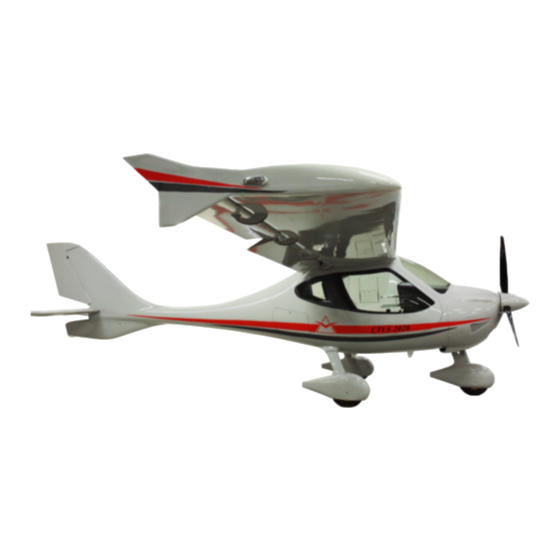
The Flight Design CTLS is a three-axis control, high-wing, and two seats light sport aircraft of normal scheme with a cruciform tail. The primary structures are made of carbon fiber reinforced plastic. The aircraft is equipped with an all-moving stabilator with a trim tab and tricycle landing gear with a steerable nose-wheel. -
Page 11: Care And Cleaning Of Your Ct
The Rohacell foam, while highly resistant to fuel, is not resistant to strong Alkali cleaners or even water with very high alkali content. Therefore Flight Design requires that the cleaners used on the CTLS be PH neutral. Cleaners, such as Fantastik®, Formula 409®, Carbonex® and Castrol Super Clean®, which are otherwise good Alkali cleaning products, should not be used on the CTLS. -
Page 12: Views, Dimensions
Maintenance and Inspection Procedures Manual CTLS Type: Series: Page: 1-3 1.4 Views, dimensions AF 04800001 Revision No. 3 Date: 14 Sep 2008... - Page 13 Maintenance and Inspection Procedures Manual CTLS Type: Series: Page: 1-4 Geometry Max. length 6604 mm 21 ft 8 in Max. height 2342 mm 7 ft 8 in Wing span 8594 mm 28 ft 2 in Areas Wing 9.98 m 107.43 sq ft Stabilator 1.60 m 17.20 sq ft...
-
Page 14: Construction Materials
Maintenance and Inspection Procedures Manual CTLS Type: Series: Page: 1-5 1.5 Construction Materials The airframe is made of high-quality composite materials which permit excellent aerodynamic characteristics to be achieved at an efficient structural mass. Due to the strict mass regulations for ultra- light aircraft, re-inforced carbon and aramide fiber materials predominate. -
Page 15: Equipment List
Maintenance and Inspection Procedures Manual CTLS Type: Series: Page: 1-6 1.6 Equipment List Each aircraft is delivered with an initial equipment list as part of this handbook. A new equipment list must be compiled and added to aircraft logbook and to this manual when there is any change to the equipment. The owner of the aircraft is responsible for ensuring that the equipment list is current. -
Page 16: Source To Purchase Parts
CTLS Type: Series: Page: 1-7 1.7 Source to Purchase Parts Spare parts can be ordered from Flight Design USA (www.flightdesignusa.com ) along the Parts and Assemblies Manual. 1.8 List of Disposable Replacement Parts Air filter Air filter C2039, Art. C9997770 Fuel filter Fuel Filter 5/16’’, Art C9997813G... -
Page 17: Weight And Balance Information
Maintenance and Inspection Procedures Manual CTLS Type: Series: Page: 1-8 1.9 Weight and Balance Information Maximum take off weight: 1320 lbs 600 kg Typical empty weight: 683 lbs 310 kg Typical useful load 622 lbs 290 kg Maximum weight per seat: 260 lbs 118kg Maximum baggage weight per side:... - Page 18 Maintenance and Inspection Procedures Manual CTLS Type: Series: Page: 1-9 Note: Sample weight and balance sheet only; not valid for the actual aircraft. AF 04800001 Revision No. 3 Date: 14 Sep 2008...
-
Page 19: Tire Inflation Pressure
Maintenance and Inspection Procedures Manual CTLS Type: Series: Page: 1-10 1.10 Tire Inflation Pressure Main wheels: 29 PSI / 2 bar Nose wheel: 29 PSI / 2 bar 1.11 Approved Fluids and Capacities Quality automotive motor oil as specified by the engine manufacturer has to be used. The engine is not approved for aircraft motor oil. -
Page 20: Recommended Fastener Torque Values And Bolts Installation
Maintenance and Inspection Procedures Manual CTLS Type: Series: Page: 1-11 1.12 Recommended Fastener Torque Values and Bolts Installation ATTENTION! All bolts has to be mounted up to down, inside to outside or front to aft, unless explicitly stated otherwise. Bolt Bolt M5 DIN Bolt M6 DIN Bolt M8 DIN... -
Page 21: General Safety Information
Maintenance and Inspection Procedures Manual CTLS Type: Series: Page: 1-12 1.13 General Safety Information ATTENTION! During all service and repair work beware of activating the Ballistic Parachute system rocket! While running the engine on the ground, keep away from the propeller. An accidental engine start is very dangerous! Ensure that the Ignition Switch C9997199 and main switches [Pushbutton Thermal, 30A C9997190B, Pushbutton Thermal 109S, 25A C9997190 (Fig. -
Page 22: Instructions For Reporting Possible Safety Of Flight Concerns Found During Inspection / Maintenance
Aircraft Make/Model and S/N Engine Make/Model and S/N Date of inspection TT Airframe TT Engine Description of the un-airworthy items found or by writing: Flight Design USA Woodstock Airport 91 Route 169, P.O. Box 325, South Woodstock, CT. 06267 e-mail: flightdesignusa@rcn.com www.flightdesignusa.com using Service Difficulty Report Form (Appendix III). -
Page 23: Minimum Levels Of Certification
An Airframe and Powerplant mechanic as defined by 14 CFR Part 65 in the U.S. or equivalent certification in other countries. For and questions or comments regarding maintenance procedures or minimum levels of certification, email Flight Design USA at airworthiness@fiightdesignusa.com AF 04800001 Revision No. -
Page 24: Required Certification Level For Maintenance Procedures
Maintenance and Inspection Procedures Manual CTLS Type: Series: Page: 2-2 2.3 Required certification level for maintenance procedures In accordance with applicable standards, the requirements for minimum levels of certification and task specific training are listed through out this manual. The following table provides an overview on the allocation of certification levels through out this manual. - Page 25 Repair Station, prior experience will be considered when determining the training required. Important: Participation in training described in this manual shall not be construed as an implicit authorization by Flight Design to perform inspections or repairs beyond the limitations set forth in the applicable regulations of the governing aviation authority.
-
Page 26: Aircraft Inspections
Condition inspection checklist Owner’s Name: ________________________________________________ Inspector’s Name: ______________________________________________ Aircraft Make/Model: Flight Design CT / _________________. S/N: __________________. Engine Make/Model: ____________________________________. S/N: __________________. Date of Inspection: _____________ TT Airframe: __________________ TT Engine: ___________________ AF 04800001 Revision No. -
Page 27: Aircraft Records
Maintenance and Inspection Procedures Manual CTLS Type: Series: Page: 3-2 3.1 Aircraft Records CT Inspection and/or Required Maintenance Checklist Aircraft logbooks. Determine total times, times since overhaul and times since last required or recommended maintenance checks and RLSA-M record on Inspection Coversheet. Safety Directives (SD’s), Airworthiness Directives (AD’s) and Service Bulletins. -
Page 28: Run-Up
Maintenance and Inspection Procedures Manual CTLS Type: Series: Page: 3-3 3.2 Run-up Run-up shall be done prior to any inspection. Run-up shall at least take long enough to bring all temperatures to levels acceptable for takeoff. Inspection: CT Inspection and/or Maintenance Checklist 1. -
Page 29: Post-Run-Up
Maintenance and Inspection Procedures Manual CTLS Type: Series: Page: 3-4 3.3 Post-Run-up CT Inspection and/or Required Maintenance Checklist Engine cowling. Remove engine cowling. RLSA-M Engine oil. Check the level of oil and follow the Operator’s Manual for RLSA-M all versions of ROTAX 912. Exterior lights. -
Page 30: Propulsion System
Maintenance and Inspection Procedures Manual CTLS Type: Series: Page: 3-5 3.4 Propulsion System CT Inspection and/or Required Maintenance Checklist Cleaning. Clean the engine as required in the Maintenance Manual Owner/Pilot for ROTAX Engine Type 912 Series. Engine. Inspect all systems as required in the Maintenance Manual Owner/Pilot for ROTAX Engine Type 912 Series. -
Page 31: Fuselage
Maintenance and Inspection Procedures Manual CTLS Type: Series: Page: 3-6 CT Inspection and/or Required Maintenance Checklist Engine mount. Lift up the nose landing gear off of the ground and inspect for cracks, corrosion, loose hardware, chafing by cables, RLSA-M wires, hoses, etc., and make sure that any flexing item is secured to the engine mount. -
Page 32: Wings
Maintenance and Inspection Procedures Manual CTLS Type: Series: Page: 3-7 3.6 Wings CT Inspection and/or Required Maintenance Checklist Wing Attachment Area. Inspect wing spar and main bolt bushings for cracks and debonding. Check visible attaching hardware for loss of torque. Inspect aileron bellcranks for cracks and corrosion. Check RLSA-M root rib pins for debonding and cracks, and the forward one for fuel leak. -
Page 33: Empennage
Maintenance and Inspection Procedures Manual CTLS Type: Series: Page: 3-8 CT Inspection and/or Required Maintenance Checklist Pitot port. Inspect for obstruction of Pitot, signs of damage, which may affect proper airflow. Remove the Pitot port before attempting to RLSA-M clear any obstructions, making sure the port is not damaged in any way. -
Page 34: Landing Gear
Maintenance and Inspection Procedures Manual CTLS Type: Series: Page: 3-9 3.8 Landing Gear CT Inspection and/or Required Maintenance Checklist Visual inspection. Inspect from top to bottom for scratches, cracks, corrosion, signs of overstress and side-loading. Visually inspect the Owner/Pilot struts for straightness. See Chapters 4.2.1.6.1 and 4.2.2.6.1. Wheels. -
Page 35: Cabin And Baggage Compartment
Maintenance and Inspection Procedures Manual CTLS Type: Series: Page: 3-10 3.9 Cabin and Baggage Compartment CT Inspection and/or Required Maintenance Checklist Fire extinguisher. Remove fire extinguisher (if applicable) and check RLSA-M that expiry date is not exceeded. Replace if necessary. Inspect general condition,... - Page 36 Maintenance and Inspection Procedures Manual CTLS Type: Series: Page: 3-11 CT Inspection and/or Required Maintenance Checklist Main landing gear attachment boxes. Inspect for cracks, debonding RLSA-M and security of hardware. Floor (pyramid), tunnel, fuselage root ribs, spar box, A-struts. RLSA-M Inspect for cracks, holes, debonding and general condition.
-
Page 37: Inspection Completion
Maintenance and Inspection Procedures Manual CTLS Type: Series: Page: 3-12 3.10 Inspection Completion CT Inspection and/or Required Maintenance Checklist Fuselage and wings. Make sure aircraft is free of any tools, parts, and debris, and reinstall all access panels, fairings, seats, and so on, Owner/Pilot removed for the inspection. -
Page 38: Structures
Maintenance and Inspection Procedures Manual CTLS Type: Series: Page: 4-1 4 Structures 4.1 Wing 4.1.1 Wing Structure The wing of CT consists of right and left wings made of carbon and fiberglass composite parts bonded together with structural epoxy resin. The wing is attached to the fuselage by means of a carry through structure developed by extensions of both right and left wing spars fixed together by two main bolts in the cabin. -
Page 39: Wing Installation And Removal
Line 4.1.2.4 Minimum Level of Certification Repairman, Light Sport Aircraft-Maintenance (RLSA-M) or higher. Flight Design task specific training required. 4.1.2.5 Wing Installation Note: If installing a replacement wing or repaired wing that requires wing root contouring, explicit Flight Design task specific training required. - Page 40 Maintenance and Inspection Procedures Manual CTLS Type: Series: Page: 4-3 Fig. 3 4) Connect all fuselage-to-wing wiring, e.g. connect the position and strobe lights socket and plug (1) (Fig. 4). Fig.4 5) Match the groove on the tip (1) with the flap pin (2) (Fig. 5, Fig. 6). Fig.
- Page 41 Maintenance and Inspection Procedures Manual CTLS Type: Series: Page: 4-4 Fig. 6 6) Match the hole of the aft bushing KA1000101 on the fuselage with the pin on the wing root rib KA2010301 (1), Fig. 7. Fig. 7 7) Match the hole in the forward bushing KA1000110 of the fuselage with the pin of the wing root rib KA2010301 (1), Fig.
- Page 42 Maintenance and Inspection Procedures Manual CTLS Type: Series: Page: 4-5 Fig. 8 8) Set the pins of the wing root rib KA2010301 up to the stop into the forward KA1000110 and aft KA1000101 bushings on the fuselage. Take care that the flap pin KA2040013 gets into the groove of the tip KA6030201 (Fig.
- Page 43 Maintenance and Inspection Procedures Manual CTLS Type: Series: Page: 4-6 11) Match the hole of the spar bushing of the right wing KA2010102 with the hole of the bushing of the left wing KA2010103 from the right side moving the wing up and down (Fig. 9). Fig.
- Page 44 Maintenance and Inspection Procedures Manual CTLS Type: Series: Page: 4-7 Fig. 13 13) Repeat item 11 for the second main bolt KA2000010. 14) Secure the main bolts with the cap and bolt, e.g. set the caps KA2000013 (1) onto the main bolts KA2000010 and fix them by bolts М8x35 С9996078А...
- Page 45 Maintenance and Inspection Procedures Manual CTLS Type: Series: Page: 4-8 Fig. 15 17) Fuel hose is attached to the connection 1, Fig. 16. Fig. 16 After wing installation the fuel system must be checked as described in Section 6 of this Warning: manual! AF 04800001...
-
Page 46: Wing Removal
Maintenance and Inspection Procedures Manual CTLS Type: Series: Page: 4-9 4.1.2.6 Wing Removal Drain all the fuel from the wings, fuel lines, and gascolator. The process of draining the aircraft should be performed in a ventilated area with fire precautions taken. The rest of the wing removal process goes in reverse to the wing installation process. -
Page 47: Landing Gear
Maintenance and Inspection Procedures Manual CTLS Type: Series: Page: 4-10 4.2 Landing Gear CT is equipped with conventional tricycle landing gear. The main gear legs made of high strength composite material are attached to the main bulkhead located behind the pilot seats. The nose gear is equipped with a shock absorber and attached to the engine mount. -
Page 48: Inspections
Maintenance and Inspection Procedures Manual CTLS Type: Series: Page: 4-11 Fig. 1 4.2.1.4 Inspections 4.2.1.4.1 Type of Maintenance Line 4.2.1.4.2 Minimum Level of Certification Owner/Pilot 4.2.1.4.3 Visual Inspection 1) The strut and fork for damages, dents, cracks, paint detachment (Fig. 1). Pay specific attention to welding seam areas. -
Page 49: Shock Absorber Inspection
4) For all items above, thoroughly inspect with all removable items off at least (cowlings, fairing (Fig. 1, item 2) and so on). In case of a hard landing, inspect right after the landing. NOTE: If damages are found per items 1 through 4, inform directly Flight Design for inspection and further instructions. -
Page 50: Nose Gear Removal (Replacement)
Maintenance and Inspection Procedures Manual CTLS Type: Series: Page: 4-13 4.2.1.5 Nose Gear Removal (Replacement) 4.2.1.5.1 Type of Maintenance Heavy 4.2.1.5.2 Minimum Level of Certification Repairman, Light Sport Aircraft-Maintenance (RLSA-M) or higher. 4.2.1.5.3 Fork Removal Fig. 2 AF 04800001 Revision No. 3 Date: 14 Sep 2008... -
Page 51: Before Installation
Maintenance and Inspection Procedures Manual CTLS Type: Series: Page: 4-14 Unscrew the nut C9996334 (Self-locking nut DIN 985-M6, regular) that fixes the bolt C9996064 (Bolt DIN 912 M6x60-8.8) by a 10х13 wrench and hex-nut wrench 5. Slightly rocking and pressing the lever KA4010001 Rocker (Fig. 2), remove the bolt C9996064 and release the lever by holding the nose wheel axle. -
Page 52: Fork Replacement
Maintenance and Inspection Procedures Manual CTLS Type: Series: Page: 4-15 4.2.1.5.6 Fork Replacement Make sure that all operations from the “Before Installation” section are done! Before lever KA4010001 Rocker (Fig. 2) installation: a. Insert the fork into the engine mount, remove the support from under the fuselage and set the plane onto the three wheels. -
Page 53: Nose Wheel
Maintenance and Inspection Procedures Manual CTLS Type: Series: Page: 4-16 4. Make sure of integrity of the Polyurethane Damper Elements (Urelastfeder 90 Shores (red 25/10,5 mm. X 20 mm)) (pos. 12). Replace if necessary 5. Clean mating surfaces from remaining grease and debris, specifically care about friction surfaces of the bronze bushings. - Page 54 Maintenance and Inspection Procedures Manual CTLS Type: Series: Page: 4-17 Make sure that only new nuts are used! Wheel removal is possible without nose gear fork disassembling. 1) Unscrew the two bolts C9996059 (Bolt DIN 912 M6x30-8.8) by a hex-nut wrench 5 and release the nose wheel fairing.
-
Page 55: Main Landing Gear
Maintenance and Inspection Procedures Manual CTLS Type: Series: Page: 4-18 4.2.2 Main Landing Gear The main landing gear of the CTLS is made from composite materials and is of the cantilever spring type. The cantilever spring ensures harmonic deflection behavior with good damping. The two separate struts (left / right) are mounted in a bearing in the fuselage. -
Page 56: General
In case of hard landing inspect immediately after landing. If damage is found, contact directly Flight Design for inspection and making decision on further actions. -
Page 57: Procedure
Maintenance and Inspection Procedures Manual CTLS Type: Series: Page: 4-20 4.2.2.5.3 Procedure Fig. 2 Unscrew the bolt C9996054B (Bolt DIN 912 M6x16-8.8), Fig. 2, by a hex-nut wrench 5. Unscrew three screws C9996162 (Screw ISO 7380 M5x16) by a hex-nut wrench 3, holding the wheel fairing. -
Page 58: Main Wheel Removal And Installation
Maintenance and Inspection Procedures Manual CTLS Type: Series: Page: 4-21 4.2.2.6 Main Wheel Removal and Installation 4.2.2.6.1 Type of Maintenance Line 4.2.2.6.2 Minimum Level of Certification Owner/Pilot 4.2.2.6.3 Wheel Brake Line Disconnecting Unscrew the nut (Fig. 3, pos. 1) from C9997417E (Fuel L-adapter A-Wek-6/4-1/8-MSv) and disconnect the line C9997205R (6x4 nylon tube) (Fig. -
Page 59: Before Installation
Maintenance and Inspection Procedures Manual CTLS Type: Series: Page: 4-22 Fig. 4 4.2.2.6.5 Before Installation Inspect the bolts for burrs, dents and thread integrity. Replace, if there is any doubt about bolt condition. Inspect the wheel attachment for dents and cracks, mounting holes for integrity and circularity. Replace, if necessary. -
Page 60: Removal (Replacement) Of Main Strut Fairing
Maintenance and Inspection Procedures Manual CTLS Type: Series: Page: 4-23 4.2.2.7 Removal (Replacement) of Main Strut Fairing 4.2.2.7.1 Type of Maintenance Line 4.2.2.7.2 Minimum Level of Certification Repairman, Light Sport Aircraft-Maintenance (RLSA-M) or higher. Fig. 5 Take out the main wheel fairing (KF32100010, KF32100011). Refer to section 4.2.2.7. Detach the wheel. -
Page 61: Type Of Maintenance
4.2.2.8.1 Type of Maintenance Line 4.2.2.8.2 Minimum Level of Certification Repairman, Light Sport Aircraft-Maintenance (RLSA-M) or higher. Flight Design task specific training required. 4.2.2.8.3 Procedure 1. Take out the seats. 2. Set an aircraft on a locating block. 3. Detach a wheel (refer to section 3.3.2.7). -
Page 62: Wheel Inspection And Maintenance
Maintenance and Inspection Procedures Manual CTLS Type: Series: Page: 4-25 Make installation of the new main gear leg in the reverse sequence. If necessary, refer to sections 4.2.2.7 and 4.2.2.6. Notes: 1. If necessary replace the C9993111B Perbunan gasoline-proof rubber NBR 80 Gas, 2mm (Fig. 6, item 5) using C9993947N TESAFIX 50m x 0.006m. - Page 63 Maintenance and Inspection Procedures Manual CTLS Type: Series: Page: 4-26 9. Inspect the tube for integrity. Inspect the tire for foreign objects. Inspect metal parts of the wheel contacting the tube for sharp edges and nicks. Apply talcum onto the inner surface of the tire and onto the tube.
-
Page 64: Brake System
Maintenance and Inspection Procedures Manual CTLS Type: Series: Page: 4-27 4.2.3 Brake System 4.2.3.1 Tools Required Wrench 7x8 1 pcs Wrench 10x13 1 pcs Wrench 11 1 pcs Wrench 12x14 1 pcs Hex-nut wrench 3 1 pcs Hex-nut wrench 4 1 pcs Hex-nut wrench 5 1 pcs... -
Page 65: Inspection Of Wheel Brakes
Maintenance and Inspection Procedures Manual CTLS Type: Series: Page: 4-28 Fig. 1 4.2.3.3.4 Inspection of Wheel Brakes Check for the necessary level of brake fluid (0.5 of the tank C9997813G Fuel Filter 5/16’’), Fig. 1, a, visually before flight. Check the brake control handle (item 1, Fig. 2) for play (up to 1 ”... -
Page 66: Inspection Of Brake Controls
Maintenance and Inspection Procedures Manual CTLS Type: Series: Page: 4-29 4.2.3.3.5 Inspection of Brake Controls Fig. 2 Remove the access panel KA6010001 (Access Panel) for inspection. For that remove the knobs (item 2, Fig. 2) using a hex-nut wrench 4 from the levers (items 1, Fig. 2) and unscrew the four screws C9996161 (Screw ISO 7380 M5x12). - Page 67 Maintenance and Inspection Procedures Manual CTLS Type: Series: Page: 4-30 Fig. 3 Check the control lever (items 1, Fig. 2, Fig. 3), brake cylinder KA7030100 (Brake cylinder), and parking brake C9997419A (Fuel valve K-MI-561-1/8-22-II-MSV) (Fig. 2, Fig. 3) for operating. to get full access to brake system controls remove the access panel (item 3, Fig.
-
Page 68: Filling Brake System With Fluid
IV and check the system. In case of unsatisfactory operation of the brake system after followed by carrying out all said above operations, immediately contact Flight Design for inspection and making decision on further action. 4.2.3.4 Filling Brake System with Fluid 4.2.3.4.1 Type of Maintenance... -
Page 69: Type Of Maintenance
Maintenance and Inspection Procedures Manual CTLS Type: Series: Page: 4-32 8. Unscrew the connector A 1 to 2 turns by a 7x8 wrench (Fig. 5). 9. Add as more brake fluid as enough to eliminate air bubbles nearby the caliper C9997205U Caliper. -
Page 70: Flight Controls
Maintenance and Inspection Procedures Manual CTLS Type: Series: Page: 4-33 4.3 Flight Controls 4.3.1 Aileron The ailerons are made of aramid top and bottom skins, carbon web and three glass fiber composite ribs. The aileron is attached to the wing by two hinged brackets. The ailerons are activated via push rods which run from the control stick through the tunnel to the mixer in the baggage compartment behind the main frame. -
Page 71: New Design Of Aileron Control System
Maintenance and Inspection Procedures Manual CTLS Type: Series: Page: 4-34 4.3.1.1 New design of aileron control system. Design of Aileron and Flap control systems were updated. All elements of the Control systems were installed and starting from the airplane S/N 08-03-05, except for planes 08-03-07, 08-03-08, 08-03-09, 08-03-10, 08-03-11, where the previous system still was installed. -
Page 72: Tools Required
Maintenance and Inspection Procedures Manual CTLS Type: Series: Page: 4-35 4.3.1.2 Tools Required Wrench 10 2 pcs Wrench 8 1 pcs Hex-nut wrench 3 1 pcs Hex-nut wrench 4 1 pcs Hex-nut wrench 5 1 pcs Electronic level 1 pcs Flexible 5 hex-head screwdriver 1 pcs Screw driver with header 10... -
Page 73: Bracket Inspection
Maintenance and Inspection Procedures Manual CTLS Type: Series: Page: 4-36 4.3.1.5.3 Bracket Inspection Inspect the wing brackets for security and play (KW2010030, KW2010040 for the right wing, and KW2020030, KW2020040 for the left wing). Torque the bolts (С9996286Р Bolt DIN 912 M6x35, A2) by a 5 hex-head screwdriver and screwdriver with header 10 in case of play. -
Page 74: Rods / Bellcranks Inspection
0.5 mm, replace the bearing. Play of the control stick tip should not exceed 5/128” / 1 mm. Otherwise inform directly Flight Design USA for inspection and further instructions. Lubricate the bearings with LITOL-24M (Retinax EP 2. Alvania EP-2 (SHELL); Alvania Grease R3 (Petroleum Co, Ltd);... - Page 75 Maintenance and Inspection Procedures Manual CTLS Type: Series: Page: 4-38 Fig. 3 Using a washer С99965604 (Washer DIN 125 A2B-6.4 mm) and the nut (5) (C9996334, Self-locking nut DIN 985-M6, regular) fix the bolts KA2020005 and KW2020007 (3). Use new nuts only. Torque the nut with two 8x10 wrenches to 80 lb-in /9 Nm, Fig.
- Page 76 Maintenance and Inspection Procedures Manual CTLS Type: Series: Page: 4-39 Fig. 5 Unscrew the nut C9996334 (Self-locking nut DIN 985-M6, regular) by a 10 wrench and 5 hex-hut wrench. Disconnect the rod (KA6020030R) from the internal bellcrank. Fig. 5. Connect the rod (3) (KA6020030R) with the bearing (1) (С9997006А, Rod end bearing, ext. thread GA6), that is fixed to the aileron root rib as shown (Fig.
- Page 77 Maintenance and Inspection Procedures Manual CTLS Type: Series: Page: 4-40 Set the external bellcrank (2) КА6020040 so that the line between the rod (1) attachment hole and bellcrank axle of rotation is perpendicular to the root rib (Fig. 7). At the same time the internal bellcrank must be set so that the line between the rod КW6020010 mounting hole and bellcrank axle of rotation is parallel to the rib of the wing.
- Page 78 Maintenance and Inspection Procedures Manual CTLS Type: Series: Page: 4-41 Install the wings (1 and 2) onto the fuselage. Fix them by the main bolts (3) КА2000010. Fig. 8. While installing the wings make sure that the pin in the flap root bracket (1) (КА2040010L for the left wing, KA2040010R for the right wing) gets into slot in the tip of the flap rod (2) КА6030200 (Transverse rod).
-
Page 79: Aileron Adjustment
4.3.1.7.2 Minimum Level of Certification Repairman, Light Sport Aircraft-Maintenance (RLSA-M) or higher. Flight Design task specific training required. 4.3.1.7.3 Rigging Aileron “Zero” Position “Zero” position of the ailerons is the position when the ailerons are aligned to the flaps in -6° (-12°) cruise configuration. - Page 80 Maintenance and Inspection Procedures Manual CTLS Type: Series: Page: 4-43 Fig. 11 3. Match the holes in the rod tip (С9997006А, Rod end bearing, ext. thread GA6) with the hole in the bellcrank (2) КА6020040 (Fig. 7). Note that when the external bellcrank (2) КА6020040 is set so that the line between the rod (1) attachment hole and bellcrank axle of rotation is perpendicular to the root rib (Fig.
-
Page 81: Aileron Deflection Adjustment
Maintenance and Inspection Procedures Manual CTLS Type: Series: Page: 4-44 4.3.1.7.4 Aileron Deflection Adjustment 1. Aileron deflections are defined in the deflection table. Aileron deflection adjustment follows the same principle in both aileron control variants. 2. Aileron deflection (flaps in position -6º) can be adjusted by changing the length of the rods in the system of aileron control (vertical rods pos. -
Page 82: Measuring Aileron Deflection
Maintenance and Inspection Procedures Manual CTLS Type: Series: Page: 4-45 4.3.1.7.5 Measuring Aileron Deflection Any adjustment of the aileron control system must be documented in an adjustment report. You can find the template starting the nominal values and allowable tolerances in the Appendix of this maintenance manual. - Page 83 Maintenance and Inspection Procedures Manual CTLS Type: Series: Page: 4-46 Photo 2.1 Step 3: Deflect the aileron in lower position by control stick. Place between markers on the pattern must coincide with the aileron trailing edge (see photo 3). Markers on the pattern define boundary values of maximum deflection angle.
-
Page 84: Verification Of Aileron Installation And Adjustment
Maintenance and Inspection Procedures Manual CTLS Type: Series: Page: 4-47 Photo 3.1 Step 4. Repeat operations 2 and 3 for the other aileron. 4.3.1.8 Verification of Aileron Installation and Adjustment 1. Inspect per section 4.3.1.7. 2. Check aileron deflection (section 4.3.1.10.1). 3. -
Page 85: Flaps
If extension speed is below the maximum speed for flap extension as given in the handbook, the next Flight Design service station should be contacted. The flap control circuit breaker is to be found directly adjacent to the flap controls. It will pop if the flap servo is continuously over-loaded. -
Page 86: General
Maintenance and Inspection Procedures Manual CTLS Type: Series: Page: 4-49 4.3.2.3 General 1. Unless otherwise specified the instructions below concern both right and left flaps. 2. To increase (reduce) length of a rod: a) Release the rod tips, having loosened the locking nut by an 8x10 wrench. b) Take care that the tips are screwed into the threaded adjuster bushing body at least 15/16”... -
Page 87: Wing Bracket Bearings Inspection
Maintenance and Inspection Procedures Manual CTLS Type: Series: Page: 4-50 Inspect the flap brackets (KW2040010R, KW2040020R, and KW2040030R for the right wing, or KW2040010L, KW2040020L and KW2040030L for the left wing) for play. In case of play torque the bolts С9996221 (Bolt DIN 7991 M5x16 A2) to 49 lb-in / 5.5 Nm by a hex-nut wrench 3, and bolts С9996286К... -
Page 88: Rods / Bellcranks Inspection
Heavy 4.3.2.5.2 Minimum Level of Certification Repairman, Light Sport Aircraft-Maintenance (RLSA-M) or higher. Flight Design task specific training required. 4.3.2.5.3 Procedure Match the hole in the root flap bracket (1) (KW2040010R for the right wing, or KW2040010L for the left wing) with the hole in the bushings of the bearing of the wing bracket No.1 (2) (KW2010010 for the right... - Page 89 Maintenance and Inspection Procedures Manual CTLS Type: Series: Page: 4-52 Fig. 3 Match the holes in the outer flap bracket (1) (KW2040030R for the right wing or KW2040030L for the left wing) with the hole in the bushing of the bearing of the wing bracket No.3 (2) (KW2010030 for the right wing or KW2020030 for the left wing) and connect them by the bolt (3) КА2020006 Fig.
-
Page 90: Type Of Maintenance
4.3.2.6.2 Minimum Level of Certification Repairman, Light Sport Aircraft-Maintenance (RLSA-M) or higher. Flight Design task specific training required. 4.3.2.6.3 Rigging “Zero” Position of the Flaps “Zero” position is the position of the flaps when the top skin of the flaps is aligned with the top of the fuselage. -
Page 91: Flap Deflection Adjustment
Maintenance and Inspection Procedures Manual CTLS Type: Series: Page: 4-54 (Transverse rod tube, left) by 3 hex-nut wrench up to bolts С9996042 (Bolt DIN 912 M5x45- 8.8). Fig. 7. Fig. 7 6) Tighten the nut C9996333 (Self-locking nut DIN 985-M5, regular) on the bolt С9996042 (Bolt DIN 912 M5x45-8.8) by an 8 wrench and 4 hex-nut wrench. - Page 92 Maintenance and Inspection Procedures Manual CTLS Type: Series: Page: 4-55 Flap deflection can be adjusted by the flap control panel. Check flap angle of deflection after each adjustment by means of electronic level. 1. Connect printed circuit board (PCB) connectors with corresponding headers of the flap actuator control (Control Card MT-10) wiring harness (Fig.
-
Page 93: Measuring Flap Deflection
Maintenance and Inspection Procedures Manual CTLS Type: Series: Page: 4-56 4.3.2.6.5 Measuring Flap Deflection Any adjustment of the flap control system must be documented in an adjustment report. You can find the template starting the nominal values and allowable tolerances in the Appendix of this maintenance manual. - Page 94 Maintenance and Inspection Procedures Manual CTLS Type: Series: Page: 4-57 Photo 3 Step 5. The difference between the noted zero deflection value and the negative deflection value provided the angle of defvlection for each individual flap. Using ruler instead of deflection template: Measure distance between same corners (lowest or topmost) on the rear edge of the flap and on the rear edge on the flap tip on the fuselage (see photo 3.1).
- Page 95 Maintenance and Inspection Procedures Manual CTLS Type: Series: Page: 4-58 Photo 4 Step 8. The difference between the noted zero deflection value and the negative deflection value provided the angle of defvlection for each individual flap. Using ruler instead of deflection template: Measure distance between same corners (lowest or topmost) on the rear edge of the flap and on the rear edge on the flap tip on the fuselage (see photo 5 and 6).
-
Page 96: Inspection Of Flap Control Microswitches
Maintenance and Inspection Procedures Manual CTLS Type: Series: Page: 4-59 4.3.2.7 Inspection of Flap Control Microswitches 4.3.2.7.1 Type of Maintenance Line 4.3.2.7.2 Minimum Level of Certification Repairman, Light Sport Aircraft-Maintenance (RLSA-M) or higher. 4.3.2.7.3 Procedure Tools required: Screwdriver 1 pcs Inspection of the up limit microswitches С9997198B (Miniature switch). -
Page 97: Type Of Maintenance
Maintenance and Inspection Procedures Manual CTLS Type: Series: Page: 4-60 4.3.3 Rudder Rudder installation requires one person. To adjust rudder deflection two persons are necessary. 4.3.3.1 Tools Required Wrench 8x10 1 pcs Wrench 10x13 2 pcs Hex-nut wrench 4 1 pcs Hex-nut wrench 5 1 pcs Ruler 20 inch / 500 mm... - Page 98 Maintenance and Inspection Procedures Manual CTLS Type: Series: Page: 4-61 Fig. 1 Turn the rudder left up to the stop and set the rudder left cable (1). Prior to that the bushings КА6050001 (2) are to be installed from both sides of the thimble and tightened by the screw DIN 7991 М6х30-8.8 (3) to the rudder lower support КА3020020 (4) using a hex-nut wrench 4.
- Page 99 Maintenance and Inspection Procedures Manual CTLS Type: Series: Page: 4-62 Fig. 2 Turn the rudder right up to the stop and repeat the process for attaching the right cable to the rudder. AF 04800001 Revision No. 3 Date: 14 Sep 2008...
-
Page 100: Rudder Deflection Adjustment
Line 4.3.3.4.2 Minimum Level of Certification Repairman, Light Sport Aircraft-Maintenance (RLSA-M) or higher. Flight Design task specific training required. Fig. 3 Rudder deflection angles are defined by the stops KA4010004 (Fig. 3). Distance between the plate with a hole for the steering rod on the engine mount and the front edge of the stop has to be about 3/4inch / 20 mm. -
Page 101: Measuring Rudder Deflection
Maintenance and Inspection Procedures Manual CTLS Type: Series: Page: 4-64 To adjust rudder deflection to the right: 1) Use hex-nut wrench 5 to unscrew 2-3 turns the bolt C9996057 DIN 912 M6x20-8.8 fixing the stop KA4010004 on the right rod. 2) Move the stop KA4010004 towards the cabin 0.08-0.16 inch / 2-4 mm. - Page 102 Maintenance and Inspection Procedures Manual CTLS Type: Series: Page: 4-65 Photo 3 Step 3. Deflect the rudder to left (right) side by pushing the pedals up to the stop. Deflection angle can be read from the template. Using ruler instead of measuring template: Position a pointer marking the rear lower edge of the rudder in the neutral position.
-
Page 103: Rigging Rudder Neutral Position
Maintenance and Inspection Procedures Manual CTLS Type: Series: Page: 4-66 4.3.3.4.4 Rigging Rudder Neutral Position 1) Remove the middle panel КВ1081300 (2) from the instrument board (1) (Fig. 5). Fig. 5 2) To move rudder neutral position to the left, loosen by two 10x13 wrenches the nuts DIN 985 М8 (1) which tighten the stop plate КА6050206 (2) on the returning mechanism КА6050200 (3) (Fig.6). -
Page 104: Adjusting Of Control Cable Tension
Maintenance and Inspection Procedures Manual CTLS Type: Series: Page: 4-67 4) Check neutral position of the rudder (the rudder axle must coincide with the plane axle, Fig. 7). Repeat item 3 if necessary. Fig. 7 5) Shifting rudder neutral position to the right can be done in the same way as shifting rudder neutral position to the left, but the stop plate КА6050206 (2) has to be moved away from the engine (Fig.8). -
Page 105: Fine Adjustment
Maintenance and Inspection Procedures Manual CTLS Type: Series: Page: 4-68 After all operations listed above are completed, tension of the rudder control cables has to be checked. The required value is 25.9 ± 0.55 lbs / 11.75 ± 0.25 kgf. There exist coarse and fine adjustments. -
Page 106: Verification Of Rudder Installation And Adjustment
Maintenance and Inspection Procedures Manual CTLS Type: Series: Page: 4-69 Fig. 10 To reduce tension: 1. Look the way the threaded adjuster bushing is secured by the safety wire. Remove the safety wire. 2. Release the tips (Fig. 10, item 2), having loosened the locking nut (Fig. 10, item 3) by a 10x13 wrench. -
Page 107: Stabilator
Maintenance and Inspection Procedures Manual CTLS Type: Series: Page: 4-70 4.3.4 Stabilator CT empennage consists of a fin with a rudder and all moving horizontal tail called stabilator. The fin makes up a one piece composite structure with the fuselage and therefore is not considered within this section. -
Page 108: Tools Required
Ensure the free motion of the sheave on the axle. Inspect composite parts for cracks, paint delamination, and mounting holes for ovaling where bolts, pivots and bearings are attached. If found, contact Flight Design for making decision on further inspection and maintenance. - Page 109 Maintenance and Inspection Procedures Manual CTLS Type: Series: Page: 4-72 Fig. 1 One person is needed to install the stabilator. Prior stabilator installation, check it for balancing out of fuselage as follows. 1. Install the stabilator bracket with balancer KА3010120 (pos.1) onto the stabilator KA3010200 (Fig.
- Page 110 Maintenance and Inspection Procedures Manual CTLS Type: Series: Page: 4-73 4. Inspect stabilator balance as follows. Set the stabilator so that it can revolve on its axis under its own weight. If the upper skin does not align horizontally when stopped, correct balancing (refer to 4.2.1.8).
- Page 111 Maintenance and Inspection Procedures Manual CTLS Type: Series: Page: 4-74 5. Install the stabilator KA3010200 (Fig. 1) into the bracket КА3010120 by matching holes (pos.3) in the bracket with holes in the top and bottom skins of the stabilator. 6. Set the bolts C9996259N (Bolt DIN 931 M6x110-8.8) throw the matched holes in the bracket КА3010120 and stabilator skins, put washers C9996504 Washer DIN 125 A2B-6.4 mm, and tighten them by the nuts C9996334 (Self-locking nut DIN 985-M6, regular) using two 8x10 wrenches to torque 80 lb-in / 9 N*m.
- Page 112 Maintenance and Inspection Procedures Manual CTLS Type: Series: Page: 4-75 Fig. 3 AF 04800001 Revision No. 3 Date: 14 Sep 2008...
- Page 113 Maintenance and Inspection Procedures Manual CTLS Type: Series: Page: 4-76 Fig. 4 20. For the procedure of adjustment of stabilator and trim tab deflection refer to Section 4.3.4.7. 21. Make sure • that lock nuts on the rods of the trim tab and the bellcrank are tightened to 49lb-in / 5.5 N*m.
-
Page 114: Type Of Maintenance
Line 4.3.4.5.2 Minimum Level of Certification Repairman, Light Sport Aircraft-Maintenance (RLSA-M) or higher. Flight Design task specific training required. Fig. 5 Stabilator deflection can be adjusted by bushings КА6040007 Bushes, Fig. 5. Unscrew 2-3 turns the lock nuts С9996334 by two 10x13 wrenches to unlock the bushing КА6040007 (Bushes) for adjusting. -
Page 115: Measuring Stabilator Deflection
Maintenance and Inspection Procedures Manual CTLS Type: Series: Page: 4-78 Stabilator deflection up: • to increase stabilator deflection up screw the forward bushing КА6040007 Bush (Fig. 5) from КА6040008; • to reduce stabilator deflection up screw the forward bushing КА6040007 Bush (Fig. 5) onto КА6040008. - Page 116 Maintenance and Inspection Procedures Manual CTLS Type: Series: Page: 4-79 Photo 3 Step 3. Deflect the stabilator with the control stick control stick up to forward (rearward) stop the stick. Note detected values and determine deflection in refernce to the value read at neutral deflection (see photos 4 and 5).
- Page 117 Maintenance and Inspection Procedures Manual CTLS Type: Series: Page: 4-80 Photos 6 AF 04800001 Revision No. 3 Date: 14 Sep 2008...
-
Page 118: Measuring Of Trim Tab Deflection And Adjustment
Maintenance and Inspection Procedures Manual CTLS Type: Series: Page: 4-81 4.3.4.5.4 Measuring of Trim Tab Deflection and Adjustment Attention: Trim tab deflection can be adjusted only after stabilator deflection is set correctly. Trim tab angles of deflection can be adjusted by changing of length of the trim tab control rods Rod end КА6060010 (Fig. - Page 119 Maintenance and Inspection Procedures Manual CTLS Type: Series: Page: 4-82 Photo 2 Step 4: Select maximum tail heavy trim. Determine deflection of trim tab with stabilator in neutral. Step 5: Deflect stabilator nose up. Determine deflection of trim tab. Step 6: Select maximum nose heavy trim. Determine deflection of trim tab with stabilator in neutral. Step 7: Deflect stabilator nose down.
-
Page 120: Balancing Of The Stabilator Balancer
Heavy 4.3.4.6.2 Minimum Level of Certification Repairman, Light Sport Aircraft-Maintenance (RLSA-M) or higher. Flight Design task specific training required. 4.3.4.6.3 Procedure In case if balancing of the stabilator is necessary (replacement, repairing surface of the stabilator \ trim tab or changing stabilator bracket), it should be done by means of change of the balancer weight in small increments continuously checking balance. - Page 121 Maintenance and Inspection Procedures Manual CTLS Type: Series: Page: 4-84 4.3.4.7 Verification of Stabilator Installation and Adjustment Check stabilator deflection per section 4.2.1.7. Check trim tab deflection per section 4.2.1.7. For checking use template from Appendix I. Check push-pull cable attachments C9997092 (Push-pull cable TIPO 70), Fig. 7, for presence of grease Multipurpose plastic grease LITOL-24M ТУ...
-
Page 122: Type Of Maintenance
Repairman, Light Sport Aircraft-Maintenance (RLSA-M) or higher. Flight Design structural repairs and composite training required. Authorized Flight Design Service centers are equipped to perform structural repairs. 4.4.3 Repair Procedures Structural repairs on composites can not be defined by standard procedures. Therefore, in any case, the individual repair procedure has to be agreed with the airframe manufacturer upfront. -
Page 123: Priming
Maintenance and Inspection Procedures Manual CTLS Type: Series: Page: 4-86 Remove excessive putty using a set of sand papers in ascending grain order (first middle-grained Sandpaper 120, and then fine-grained Sandpaper 240 (Wuerth GmbH &Co). Remove the dust with a piece of water wetted cotton fabric. -
Page 124: Engine
Before performing any inspection or maintenance task on the aircraft check these manuals for available updates through ROTAX. Engine removal, installation & replacement can only be done of Flight Design USA authorized service center. Important: Rotax training may be required to perform maintenance on the engine AF 04800001 Revision No. -
Page 125: Carb Heat Control
Maintenance and Inspection Procedures Manual CTLS Type: Series: Page: 5-2 5.3 Carb Heat Control To inspect and eliminate damages of the ventilation system one person is required. 5.3.1 Tools Required Hex-nut wrench 3 (or screwdriver) 1 pcs Screwdriver 5 mm 1 pcs Cross-screwdriver or wrench with header 7 1 pcs... - Page 126 Maintenance and Inspection Procedures Manual CTLS Type: Series: Page: 5-3 1. Unscrew 6 bolts and remove the cover of the air filter box (pos. 3, Fig. 1). 2. Release the clamp by screwdriver and disconnect the filter (inside the box). 3.
- Page 127 Maintenance and Inspection Procedures Manual CTLS Type: Series: Page: 5-4 Fig. 4, a Fig. 4, b c. If the carb heat valve on the airbox does not move properly, check the cable connecting the choke and the handle and eliminate the problem as follows: 1.
-
Page 128: Fuel System
Maintenance and Inspection Procedures Manual CTLS Type: Series: Page: 6-1 6 Fuel System 6.1 General Fuel system inspection and maintenance are to be performed in a well-ventilated compartment, away from heaters and flame. A fuel tank with a capacity of 65 l is integrated into each wing. The fuel tanks are each divided into two sections by an anti-sloshing rib. - Page 129 Maintenance and Inspection Procedures Manual CTLS Type: Series: Page: 6-2 Filler cap Filler cap Filler cap Sloshing rib Sloshing rib Sloshing rib Sloshing rib Sloshing rib Sloshing rib Filler cap Filler cap Filler cap NACA nozzle NACA nozzle NACA nozzle Tank ventilation Tank ventilation Tank ventilation...
-
Page 130: Tools Required
Maintenance and Inspection Procedures Manual CTLS Type: Series: Page: 6-3 6.2 Tools Required Fuel level gauge 1 pcs Claw 1 pcs Screw-driver 1 pcs Hex-nut wrench 4 1 pcs Hex-nut wrench 5 1 pcs Wrench 6х8 1 pcs Wrench 8х10 1 pcs Wrench 10х13 1 pcs... -
Page 131: Type Of Maintenance
6.5.2 Minimum Level of Certification Repairman, Light Sport Aircraft-Maintenance (RLSA-M) or higher. Flight Design task specific training required. 6.5.3 Checking of Fuel Flow Rate Check the fuel flow per minute of each tank through the gascolator exactly and note and compare with the previous fuel flow rate. - Page 132 Maintenance and Inspection Procedures Manual CTLS Type: Series: Page: 6-5 fuel hoses, absence of fuel system blockage. Start the engine. Keep the engine working during 5-10 minutes. Stop the engine. Repeat items 6-9. Fig.1 Fig.2 Note: CTSW photos are used for illustration only, applies in the same way to CTLS aircraft. AF 04800001 Revision No.
-
Page 133: Intake Filter / Side Access Panel
Maintenance and Inspection Procedures Manual CTLS Type: Series: Page: 6-6 6.6 Intake Filter / Side Access Panel 6.6.1 Type of Maintenance Line 6.6.2 Minimum Level of Certification Repairman, Light Sport Aircraft-Maintenance (RLSA-M) or higher. 6.6.3 Procedure The fuel tank is closed by the access panel from the cabin side KA7020002R (L) (Fig. 2). Inspect the access panel and fuel level indicator joints for leaks. - Page 134 Maintenance and Inspection Procedures Manual CTLS Type: Series: Page: 6-7 • Install the access panel KA7020002R (L); • Make sure the fuel filter tube is turned towards the trailing edge of the wing and is in the lowest position (lays on the bottom skin). •...
-
Page 135: Fuel Filter
Maintenance and Inspection Procedures Manual CTLS Type: Series: Page: 6-8 6.7 Fuel Filter 6.7.1 Type of Maintenance Line 6.7.2 Minimum Level of Certification Repairman, Light Sport Aircraft-Maintenance (RLSA-M) or higher. 6.7.3 Procedure Fig. 5 Inspect for: 1. Leaks at joint of the connector (Fuel Filter 5/16’’, Fig. 5, unit 1) and hose (Fuel tube DIN 73379, 7.5x13.0). -
Page 136: Type Of Maintenance
Maintenance and Inspection Procedures Manual CTLS Type: Series: Page: 6-9 6.8 Gascolator 6.8.1 Type of Maintenance Line 6.8.2 Minimum Level of Certification Repairman, Light Sport Aircraft-Maintenance (RLSA-M) or higher. 6.8.3 Procedure Fig. 6 Inspect: 1. For leaks on connections. 2. For passing fuel through the lines and water in fuel by draining some fuel through the drain valve (item А, Fig. -
Page 137: Propeller
Maintenance and Inspection Procedures Manual CTLS Type: Series: Page: 7-1 7 Propeller 7.1 Type of Maintenance Line 7.2 Minimum Level of Certification Repairman, Light Sport Aircraft-Maintenance (RLSA-M) or higher. 7.3 Propeller Maintenance Procedures For propeller inspection and maintenance refer to the latest maintenance manual issued by the propeller manufacturer. -
Page 138: Utility Systems
Maintenance and Inspection Procedures Manual CTLS Type: Series: Page: 8-1 8 Utility Systems 8.1 Tools Required Wrench 8 1 pcs Hex-nut wrench 3 (or screwdriver) 1 pcs Hex-nut wrench 4 (or screwdriver) 1 pcs Hex-nut wrench 5 1 pcs Screwdriver 5 mm 1 pcs Hand pressing tool for rope 0.45 - 2.00 mm 1 pcs... - Page 139 Maintenance and Inspection Procedures Manual CTLS Type: Series: Page: 8-2 Fig. 2, a Fig. 2, b • When the handle is pulled (Fig. 3, а), the Cabin heater choke КА7040200 (Fig. 3, b) is ON. Fig. 3, a Fig. 3, b 3.
- Page 140 Maintenance and Inspection Procedures Manual CTLS Type: Series: Page: 8-3 Fig. 4 b. Check if the cable С9997065В Steel rope 7x7 1 mm is frayed and if there is the stop С9997816С Cable stop 1806-Z ni at the cable attachment to the Cabin heater choke КА7040200.
- Page 141 Maintenance and Inspection Procedures Manual CTLS Type: Series: Page: 8-4 Fig. 5 • Pass it through the tube С9993190Н PTFE tube 4.0x6.0 mm into the engine compartment. • Attach the cable С9997065В (Steel rope 7x7 1 mm) to the heating Cabin heater choke КА7040200 as shown by arrows at Fig.
- Page 142 Maintenance and Inspection Procedures Manual CTLS Type: Series: Page: 8-5 d. Proceed to item 4. 7. Remove the central panel from the instrument board by a 3 hex-nut screwdriver and inspect all parts of the manifold С9993188 (AERODUCT tube CEET-7 1-3/4 ID) for integrity. The manifold consist of three pieces of hose С9993188 AERODUCT tube CEET-7 1-3/4 ID (1 long piece in the engine compartment (1), long piece in the cabin (under the instrument board) (2), and the short piece (3) between the Cabin heater choke КА7040200 and КВ7040400 Air branch canal (Fig.
- Page 143 Maintenance and Inspection Procedures Manual CTLS Type: Series: Page: 8-6 b. Unscrew the bolt by a cross-screwdriver or wrench with header 7 and release the clamp С9997723 Clamp 40-60 that secures the hose С9993188 (AERODUCT tube CEET-7 1- 3/4 ID) near КВ7040300 (Air mixer) under the instrument board. Fig. 8. c.
- Page 144 Maintenance and Inspection Procedures Manual CTLS Type: Series: Page: 8-7 Fig. 9 a. Unscrew the bolt by a cross-screwdriver or wrench with header 7 and release the clamp С9997723 Clamp 40-60 that secures the hose С9993188 (AERODUCT tube CEET-7 1- 3/4 ID) near the heating Cabin heater choke КА7040200.
- Page 145 Maintenance and Inspection Procedures Manual CTLS Type: Series: Page: 8-8 d. Disconnect the springs С9997703С from the muffler КА5020500 (Muffler with exhaust pipe). Fig. 10. e. Release the nuts С9997499В (Soldering nut M8x1) by a screwdriver with header 12 (unscrew 3-5 turns towards the engine, but do not remove them). Remove the muffler КА5020500 (Muffler with exhaust pipe).
- Page 146 Maintenance and Inspection Procedures Manual CTLS Type: Series: Page: 8-9 p. Connect the hose С9993188 (AERODUCT tube CEET-7 1-3/4 ID) to the Cabin heater choke КА7040200. q. Tighten the clamp С9997723 (Clamp 40-60) by a cross-screwdriver or wrench with header 7. c.
-
Page 147: Type Of Maintenance
Maintenance and Inspection Procedures Manual CTLS Type: Series: Page: 9-1 9 Instruments and Avionics For inspect and maintenance of instruments and avionics one person is required. Tools Required Compressor 1 pcs Parts Required Tags 10 pcs Instrument Maintenance 9.3.1 Type of Maintenance Line 9.3.2 Minimum Level of Certification Repairman, Light Sport Aircraft-Maintenance (RLSA-M) or higher. -
Page 148: Analog Airspeed Indicator
Liquid must be transparent. Check for presence of deviation card and seal. 9.3.9 Flap position indicator Inspect annually for operation. If inop - contact Flight Design USA. 9.3.10 Hobbs Hour Meter Maintenance is “on-condition” only. 9.3.11 Radio Garmin SL30 with VOR functionality The SL30 unit is designed to not require any regular general maintenance except as included in this section. -
Page 149: Transponder Garmin Installation
Maintenance and Inspection Procedures Manual CTLS Type: Series: Page: 9-3 9.3.13 Transponder Garmin installation Other than for regulatory periodic functional checks, maintenance of the GTX 327 is "on condition" only. Refer to the GTX 327 Maintenance Manual. Periodic maintenance of the GTX 327 is not required. 9.3.14 Altitude Encoder ACK A30 (Classic) or Dynon (Advanced) The model A-30 Altitude Encoder requires no periodical maintenance. -
Page 150: Inspection Of Pitot & Static Port
Maintenance and Inspection Procedures Manual CTLS Type: Series: Page: 9-4 9.4 Inspection of Pitot & Static Port 9.4.1 Type of Maintenance Line 9.4.2 Minimum Level of Certification Owner/Pilot 9.4.3 Procedure At every 100 hrs inspection inspect the system for obstruction as follows. Take the Pitot tube C9997455Q (Pitot tube) out of the wing (Fig. -
Page 151: Special Equipment
Maintenance and Inspection Procedures Manual CTLS Type: Series: Page: 9-5 Fig. 2 Disconnect the tubes С9993190Н (PTFE tube 6x1) from the instruments. Attach a tag to each of the ends of tubes С9993190Н PTFE (tube 6x1) to show with instrument the ends are to be connected to. -
Page 152: Electrical System
CTLS Type: Series: Page: 10-1 10 Electrical System For a wiring diagram of the electrical system please refer the drawings supplied with the aircraft, or available at Flight Design. 10.1 Tools Required Wrench 8х10 1 pcs Wrench 10х13 1 pcs... - Page 153 Maintenance and Inspection Procedures Manual CTLS Type: Series: Page: 10-2 The major components of the electric system within engine compartment are shown on Fig. 2. Fig. 2 Electric instruments control, switch panel, ignition\starter switch and circuit breakers are located on the central console and shown on Fig.
- Page 154 Maintenance and Inspection Procedures Manual CTLS Type: Series: Page: 10-3 Fig. 3 To inspect the relais board of the flap controller, located at the firewall, remove one of the side instrument panels. (Fig. 4). Fig. 4 AF 04800001 Revision No. 3 Date: 14 Sep 2008...
- Page 155 Maintenance and Inspection Procedures Manual CTLS Type: Series: Page: 10-4 The aircraft is equipped with a Hawker Battery SBS 8 (Fig. 5). Fig. 5 NOTE: For extended service life, disconnect the battery to prevent it from being continuously charged by external power when the aircraft is in maintenance.
-
Page 156: Inspection
Maintenance and Inspection Procedures Manual CTLS Type: Series: Page: 10-5 10.3.1 Inspection 10.3.1.1 Type of Maintenance Line 10.3.1.2 Minimum Level of Certification Owner/Pilot 10.3.1.3 Procedure Inspect wiring insulation for integrity. Replace wire, if insulation is damaged. Inspect studs connection annually. Tighten bolt connections and re-braze soldered connections. Inspect each electric instrument for secure ground connection (Fig. -
Page 157: Appendix I . Template For Trim Tab Deflection Angles Measurement
Maintenance and Inspection Procedures Manual CTLS Type: Series: Page: AI-1 Appendix I . Template for Trim Tab Deflection Angles Measurement For checking trim tab deflection angles: 1. Cut out two parts of template and glue them together through A-A line. 2. - Page 158 Maintenance and Inspection Procedures Manual CTLS Type: Series: Page: AI-2 AF 04800001 Revision No. 3 Date: 14 Sep 2008...
- Page 159 Maintenance and Inspection Procedures Manual CTLS Type: Series: Page: AI-3 AF 04800001 Revision No. 3 Date: 14 Sep 2008...
-
Page 160: Appendix Ii. Adjustment Report
Maintenance and Inspection Procedures Manual CTLS Type: Series: Page: AII-1 Appendix II. Adjustment report Adjustment report 1 Airplane serial number: Inspector: Control surface Position Limits, degrees/mm Actual, Note degrees/mm up (deg) 12 deg, Tol.+1 deg, -1 deg Flap left up (mm) down (deg) 35 deg, Tol.+1 deg, -1 deg Flap left... - Page 161 Maintenance and Inspection Procedures Manual CTLS Type: Series: Page: AII-2 Adjustment report 2 Airplane serial number: Inspector: Control surface Position Limits, degrees/mm Actual, Note degrees/mm up (deg) 5.5 deg, Tol.+0.5 deg, -0.5 Flap left up (mm) down (deg) 35 deg, Tol.+1 deg, -1 deg Flap left down (mm) up (deg)
-
Page 162: Appendix Iii . Service Difficulty Report Form
Maintenance and Inspection Procedures Manual CTLS Type: Series: Page: AIII-1 Appendix III . Service Difficulty Report Form AF 04800001 Revision No. 3 Date: 14 Sep 2008... -
Page 163: Appendix Iv. Matco Brake System
Maintenance and Inspection Procedures Manual CTLS Type: Series: Page: AIV-1 Appendix IV. MATCO Brake System If you have MATCO Brake System on your plane, please pay attention for the following items: 1. Nose Wheel Nose Wheel Removal: Wheel removal is possible, if nose gear fork is dismounted. 1). - Page 164 Maintenance and Inspection Procedures Manual CTLS Type: Series: Page: AIV-2 Fig 1 Fig 2 AF 04800001 Revision No. 4 Date: 02 Jan 2009...
- Page 165 Maintenance and Inspection Procedures Manual CTLS Type: Series: Page: AIV-3 2. Main Wheel Main Wheel removal Unscrew bolt М6 item 1 fig.1. Unscrew 3 screws М5 item 2 fig.2. Remove wheel fairing. Remove lock pin item3 fig.3, unscrew nut item 4 fig.3. Unscrew 3 screws item 6, remove nord-lock washers item 7 fig.3.
- Page 166 Maintenance and Inspection Procedures Manual CTLS Type: Series: Page: AIV-4 Main wheel mounting Before mounting: inspect screws item 6, nut item 4 for thread integrity. Replace, if necessary. Inspect thread area of wheel axle for thread integrity. Replace, if necessary. check brake disk (see chapter 3.2 this Appendix) Mount wheel in the reverse sequence.
- Page 167 Maintenance and Inspection Procedures Manual CTLS Type: Series: Page: AIV-5 Fig 4 NOTE: for mounting use only new nuts M6 item 9. Upon completion check brakes for functioning. AF 04800001 Revision No. 4 Date: 02 Jan 2009...
- Page 168 Maintenance and Inspection Procedures Manual CTLS Type: Series: Page: AIV-6 Items and tightening torque see in following table: Items and tightening torque Item part name torque note Screw DIN 912 M6x16 for mounting use bonding liquid middle strength Screws ISO 7380 M5x16 lock pin wheel nut Technical Service Guide MATCO mfg.
- Page 169 Maintenance and Inspection Procedures Manual CTLS Type: Series: Page: AIV-7 3. Brake System 3.1 General To inspect brake system one person is required. Prior to being put wheel chocks at each side of wheels to prevent unintended motion of plane. Brake system is consist of: main cylinder (MC-4CT) item 1 fig.1;...
- Page 170 Maintenance and Inspection Procedures Manual CTLS Type: Series: Page: AIV-8 Fig 2 Fig 3 Inspection Before inspecting remove tunnel panels item 8, 9 fig. 4. Inspect brake system before flight: 1) Check level of brake fluid inside of the tank item 11 fig.2 (has to be not less ½ of tank) visually, add fluid if necessary;...
- Page 171 Replace brake system control parts if necessary. In case of unsatisfactory operation of brake system after followed by carrying out all said above operations, immediately contact Flight Design for inspection and making decision on further action. Replacing of brake system parts.
- Page 172 Maintenance and Inspection Procedures Manual CTLS Type: Series: Page: AIV-10 Fig 5 Fig 6 AF 04800001 Revision No. 4 Date: 02 Jan 2009...
- Page 173 Maintenance and Inspection Procedures Manual CTLS Type: Series: Page: AIV-11 Brake conduits are opened at forward position of valve grip (item 12 fig.7). Brake conduits are closed at sideward position of valve grip (item 12 fig.8). System works: forward grip position – main brake, sideward position –...
- Page 174 Page: AIV-12 Fig 9 Fig 10 Note: In case of unsatisfactory operation of brake system after followed by carrying out all said above operations, immediately contact Flight Design for inspection and making decision on further action. AF 04800001 Revision No. 4...
- Page 175 Maintenance and Inspection Procedures Manual CTLS Type: Series: Page: AIV-13 Filling Brake System with Fluid - Visually check the system for integrity and tightness - Make sure the brake control handle is in most forward position - Make sure the aircraft is not set on parking brake, i.e. the valve is open - Place a can under the tank to collect brake fluid in case of overfilling.
- Page 176 Maintenance and Inspection Procedures Manual CTLS Type: Series: Page: AIV-14 Items and tightening torque table Item part name torque note Main cylinder Brake Valve Brake rod Handle activation 1, 2 Brake line Brake (caliper) Brake disk Tunnel panel Tunnel panel Rod End Tank 1,7,8...
Need help?
Do you have a question about the CTLS Series and is the answer not in the manual?
Questions and answers