Advertisement
Table of Contents
- 1 Revision Record
- 2 Kit Contents
- 3 Installation Procedure
- 4 Removing the Front Panel
- 5 Installing the Verifone UX300 MSR
- 6 Installing the Front Panel
- 7 Installing the Verifone UX100 PIN Pad
- 8 Routing the PIN Pad and MSR Cables
- 9 PIN Pad Ground Harness
- 10 UX300 MSR Power Cable
- 11 Interconnection Diagram
- Download this manual
See also:
Kit Instructions
Advertisement
Table of Contents

Related Manuals for NCR Verifone UX100


Summary of Contents for NCR Verifone UX100
- Page 1 KIT INSTRUCTIONS Verifone UX100 and UX300 Devices 7705-K046 Issue A...
-
Page 2: Revision Record
NCR, therefore, reserves the right to change specifications without prior notice. All features, functions, and operations described herein may not be marketed by NCR in all parts of the world. In some instances, photographs are of equipment prototypes. Therefore, before using this document, consult with your NCR representative or NCR office for information that is applicable and current. -
Page 3: Kit Contents
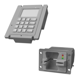
Verifone UX100 and UX300 Devices Introduction This kit provides a Verifone UX100 PIN Pad with Ground Harness and a Verifone UX300 MSR devices. Note: Before installing, the customer needs to configure these with their specific settings. These devices require one of the following 7705 Kits or Features: •... -
Page 4: Installation Procedure
Avoid any contact with internal parts and handle cards only by their external edges. To install the Verifone UX100 PIN Pad and UX300 MSR to the NCR Selferv™ 75 (7705) Kiosk, perform the following steps: 1. Shut down the Software Application and Operating System. -
Page 5: Removing The Front Panel
Verifone UX100 and UX300 Devices Removing the Front Panel 1. Inside the top box, disconnect the Private Audio Cable from the Private Audio Extension Cable. 2. Slide out the Front Panel from the Kiosk. Push the two orange latches outwards and... - Page 6 Verifone UX100 and UX300 Devices 3. Carefully place the Front Panel assembly face down on the Top Box. Note that the Speaker Harness and Proximity Detector USB Cable are still secured to the Front Panel. 4. Take note of the routing and disconnect the Speaker Harness and Proximity Detector USB Cable, cut off the cable ties securing them to the panel.
- Page 7 Verifone UX100 and UX300 Devices 5. Loosen the screws (2) securing the Proximity Detector Cover then remove the cover from the Front Panel. 6. Remove the screws (5) securing the Verifone SCR710 MTG Bracket (UX300 Bracket) to the Front Panel.
-
Page 8: Installing The Verifone Ux300 Msr
Verifone UX100 and UX300 Devices Installing the Verifone UX300 MSR 1. Mount and secure the Verifone UX300 MSR to the Verifone SCR710 MTG bracket with nuts (4). 2. Mount and secure the UX300 MSR and bracket assembly to the Front Panel with... - Page 9 Verifone UX100 and UX300 Devices 3. Mount and partially tighten screws (2) for the Proximity Detector Cover. 4. Insert and slide the Proximity Detector Cover under the partially tightened screws to mount the cover, then fully tighten the screws (2).
- Page 10 Verifone UX100 and UX300 Devices 5. Connect the following cables to the UX300 MSR: • MSR Power Cable (497-0513333 - Cable-DC Power, 12V Regulator Board to UX300) • MSR USB Cable (497-0441898 - Cable-Communications USB, 1m, Black ) • MSR to PIN Pad USB Cable (009-0021027 - Cable-USB Type A to Type B High...
-
Page 11: Installing The Front Panel
Verifone UX100 and UX300 Devices Installing the Front Panel 1. Connect the Speaker Cables to the Speakers. Note: Make sure that the correct cable wire is connected to the appropriate speaker connection terminal. • Connect "-" cable wire to "-" speaker terminal •... - Page 12 1-10 Verifone UX100 and UX300 Devices 3. Connect the Proximity Detector USB Cable to the Proximity Detector Board and secure the Cable to the Cover with a cable tie. 4. Route the Proximity Detector USB Cable under the MSR towards the left-hand side of the Front Panel.
-
Page 13: Installing The Verifone Ux100 Pin Pad
Verifone UX100 and UX300 Devices 1-11 Installing the Verifone UX100 PIN Pad 1. Remove the screws (5) securing the UX100 7705 Bracket from the Fascia. 2. Mount the UX100 PIN Pad on the UX100 7705 Bracket and secure with nuts (4). - Page 14 1-12 Verifone UX100 and UX300 Devices 3. Connect the MSR to PIN Pad USB cable (009-021027) to the UX100 PIN Pad. Route the cable over the bracket arm and secure with a cable tie.
- Page 15 Verifone UX100 and UX300 Devices 1-13 4. Mount the PIN Pad and bracket assembly on the Fascia Trim Panel and secure with screws (5). • Use two M4x12 CSK screws (007-702123) to secure the PIN Pad assembly to the upper Fascia Frame •...
-
Page 16: Routing The Pin Pad And Msr Cables
1-14 Verifone UX100 and UX300 Devices Routing the PIN Pad and MSR Cables The UX100 PIN Pad and UX300 MSR uses the following cables to connect to the the Selfserv 75 (7705) Kiosk: • MSR to PIN Pad USB Cable (009-0021027 - Cable-USB Type A to Type B High Speed) •... - Page 17 Verifone UX100 and UX300 Devices 1-15 MSR to PIN Pad USB Cable The MSR to PIN Pad USB Cable is routed from the UX100 PIN Pad along the Fascia to the Top Box through the Fascia Harness Tubing and then to the UX300 MSR.
- Page 18 1-16 Verifone UX100 and UX300 Devices 2. Remove the cable ties (7) securing the Fascia Harness to the Fascia and Top Box. 3. If a Sanko MSR was installed in the Kiosk, remove the Sankyo MSR to EBox USB Cable from the Fascia Harness Tubing.
- Page 19 Verifone UX100 and UX300 Devices 1-17 5. Route the Fascia Harness from the Fascia to the Top Box I/O Panel and secure with cable ties (7).
- Page 20 1-18 Verifone UX100 and UX300 Devices 6. Route the MSR to PIN USB cable length towards the base of the Top Box together with other cables. Secure the USB cable with cable ties as necessary. 7. Place the excess cable length on the Top Box together with other cables.
-
Page 21: Pin Pad Ground Harness
Verifone UX100 and UX300 Devices 1-19 PIN Pad Ground Harness 1. Secure the PIN Pad Ground Harness to the right-hand side of the Fascia Frame Bracket with a screw (1). 2. Secure the Ground Harness to the PIN Pad with a nut (1). - Page 22 1-20 Verifone UX100 and UX300 Devices UX300 MSR USB Cable 1. Connect the Type A connector of the MSR USB cable to one of the USB Ports on the USB Hub in the I/O Panel. The Kiosk may either have one USB HUB or two USB Hubs depending on the Kiosk configuration.
-
Page 23: Ux300 Msr Power Cable
Verifone UX100 and UX300 Devices 1-21 UX300 MSR Power Cable 1. Dismount the 12V Regulator Board. a. Loosen the screw securing the 12V Regulator and Cover assembly. b. Slide the assembly upward to dismount it then lay the assembly down on the Top Box. - Page 24 1-22 Verifone UX100 and UX300 Devices 4. Mount and secure the 12V Regulator Board and Cover assembly to the Top Box. a. Insert the tab on the bottom side of the cover through the bottom slot on the Top Box Bracket.
-
Page 25: Interconnection Diagram
Verifone UX100 and UX300 Devices 1-23 Interconnection Diagram The illustration below shows the UX100 and UX300 connection diagram with the NCR SelfServ 75 (7705) Kiosk.
Need help?
Do you have a question about the Verifone UX100 and is the answer not in the manual?
Questions and answers