Advertisement
Quick Links
INTRODUCTION
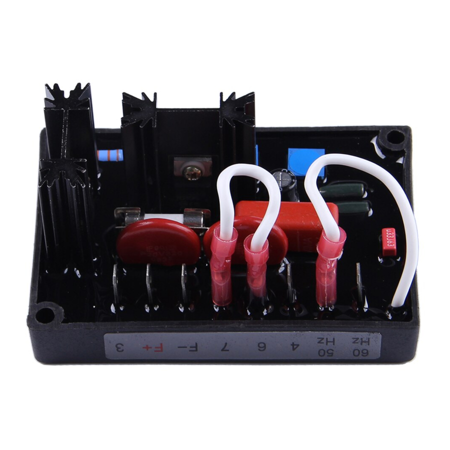
AVC63-4 and AVC63-4D analog voltage controllers regulate
voltage on 50 or 60 hertz brushless generators. The
controllers include frequency compensation, over-excitation
shutdown, solid-state buildup circuitry, and EMI filtering.
AVC63-4 adjustment potentiometers are located on the
terminals and components side of the controller (see Figure
1). AVC63-4D adjustment potentiometers are accessed
through the controller front panel (see Figure 2).
SPECIFICATIONS
Output Power
Maximum Continuous:
One Minute Forcing:
Exciter Field DC Resistance
15 to 100 Ω
Input Power
Range:
Frequency:
Burden:
Sensing Input
190 to 240 Vac, single-phase, 50/60 Hz, ±10%, common
with ac power input
Voltage Adjustment Range
171 to 264 Vac
Regulation Accuracy
Better than ±1.0%, no-load to full-load
Response Time
Less than 1.5 cycles for ±5% changes is sensing voltage
EMI Suppression
Internal electromagnetic interference (EMI) filtering
Overexcitation Shutdown
Field voltage shuts down after time delay if exciter field
voltage exceeds 100 Vdc, ±5%. (See Overexcitation
Shutdown for inverse time delay curve and description.)
Voltage Buildup
Automatic voltage buildup occurs for residual generator
voltages as low as 6 Vac.
Power Dissipation
8 W maximum
Temperature
Operating:
Storage:
Vibration
2 to 27 Hz:
27 to 52 Hz:
52 to 1000 Hz:
Shock
Withstands up to 20 G in each of three mutually
perpendicular axes.
Publication
9166800890
CALL US TODAY
CALL US TODAY
1-888-POWER-58
1-888-POWER-58
ANALOG VOLTAGE CONTROLLER
Model AVC63-4 (P/N 9166800136)
Model AVC63-4D ( P/N 9166800134 )
4 Adc at 63 Vdc (252 W)
7 Adc at 100 Vdc (700 W) with
240Vac power input
190 - 240 Vac, ±10%, single-phase
50/60 Hz, ±10%
500 VA
–40 to 140°F (–40 to 60°C)
–85 to 185°F (–65 to 85°C)
1.3 G
0.036 inches, double-amplitude
5 G
Revision
A
REQUEST A QUOTE
REQUEST A QUOTE
parts@genpowerusa.com
parts@genpowerusa.com
FOR
Weight
8 oz (220 g) net
Agency Certification
UL recognized and CSA certified
CONTROLS
AVC63-4 and AVC63-4D controls consist of jumpers and
screwdriver-adjusted potentiometers.
Jumpers
Two jumpers connect to the controller terminals: the Corner
Frequency jumper and the Voltage Adjust Rheostat jumper.
These jumpers are shown in Figure 3.
Corner Frequency Jumper
Analog voltage controllers are delivered with the Corner
Frequency Jumper set for 60 hertz operation. This gives a
corner frequency of 55 hertz. For 50 hertz operation and a
corner frequency of 45 hertz, the Corner Frequency jumper
must be moved to the 50 Hz terminal.
Voltage Adjust Rheostat Jumper
Analog voltage controllers are delivered with the Voltage
Adjust Rheostat jumper connected across terminals 6 and 7.
This enables adjustment of the generator output voltage
through the controller's internal Voltage Control potenti-
ometer. Clockwise rotation of the voltage control increases
generator voltage.
If remote adjustment of the generator output is desired, the
Voltage Adjust Rheostat jumper must be replaced with a
user-supplied rheostat. A 1000 ohm, ½-watt rheostat will
provide adequate voltage adjustment range for most
applications. Figure 8 shows the proper remote rheostat
connections.
Potentiometer Controls
AVC63-4 potentiometer controls are located on the
components and terminals side of the controller and are
shown in Figure 1. AVC63-4D potentiometer controls are
accessible through the controller front panel and are shown
in Figure 2.
INPUT POWER/SENSING INPUT
Power for the exciter field and analog voltage controller is
derived from the generator output. The acceptable power
input range is 171 to 264 Vac and is connected to terminals
3 and 4. Connect wiring as shown in the interconnection
diagram of Figure 8.
EXCITER FIELD POWER CIRCUIT
Controller terminal F+ is connected to the brushless exciter
field positive terminal and controller terminal F– is
connected to the brushless exciter field negative terminal.
The exciter field dc resistance must be 15 Ω or
greater and less than 100 Ω.
If the exciter field dc resistance is less than 15 Ω and the
full-load field current does not exceed the maximum
continuous current rating of the controller, a resistor of
First Printing: 09/03
Revised: 04/07
CAUTION
Copyright
2007
www.genpowerusa.com
www.genpowerusa.com
SHOP ONLINE
SHOP ONLINE
Advertisement

Summary of Contents for Basler AVC63-4
- Page 1 AVC63-4 adjustment potentiometers are located on the CONTROLS terminals and components side of the controller (see Figure AVC63-4 and AVC63-4D controls consist of jumpers and 1). AVC63-4D adjustment potentiometers are accessed screwdriver-adjusted potentiometers. through the controller front panel (see Figure 2).
- Page 2 Generator voltage should build up. If it does not build Mounting up, perform the steps under Field Flashing. The AVC63-4 and AVC63-4D controllers may be mounted Slowly adjust the controller’s Voltage control (or remote on the generator in any convenient position. Figure 7 shows voltage adjust rheostat) until the generator voltage the outline dimensions and drilling locations.
-
Page 3: Operational Test
(F+) and negative (F–) terminals. The dc CONTROLLER DIFFERENCES source should not be grounded and should not have an Previous versions of the AVC63-4 controller, sold prior to output greater than 12 Vdc. mid-2003, are slightly different in appearance and control Apply the dc voltage for approximately 3 seconds, then adjustment. - Page 4 Figure 3. Jumper Locations Figure 6. Overexcitation Shutdown Time Delay Characteristic Figure 4. Frequency Compensation Characteristic - 60 Hz Figure 5. Frequency Compensation Characteristic - 50 Hz Figure 7. Outline and Drilling Dimensions Page First Printing: 09/03 Revision Publication 9166800890 Revised: 04/07 CALL US TODAY CALL US TODAY...
- Page 5 Figure 8. Typical Interconnection, 208/240 V Nominal Figure 9. Operational Test Diagram Figure 10. Controller Version Heat Sink Locations Publication Revision First Printing: 09/03 Page 9166800890 Revised: 04/07 CALL US TODAY CALL US TODAY REQUEST A QUOTE REQUEST A QUOTE SHOP ONLINE SHOP ONLINE 1-888-POWER-58...
- Page 6 NOTES Page First Printing: 09/03 Revision Publication Revised: 04/07 9166800890 CALL US TODAY CALL US TODAY REQUEST A QUOTE REQUEST A QUOTE SHOP ONLINE SHOP ONLINE 1-888-POWER-58 1-888-POWER-58 parts@genpowerusa.com parts@genpowerusa.com www.genpowerusa.com www.genpowerusa.com...


