Table of Contents
Advertisement
Quick Links
Advertisement
Table of Contents

Related Manuals for Topcon IS Series


Summary of Contents for Topcon IS Series
- Page 1 INSTRUCTION MANUAL IMAGING STATION SERIES Rev.1...
-
Page 3: Foreword
FOREWORD Thank you for purchasing the TOPCON Imaging Station IS series. For the best performance of the instruments, please carefully read these instruc- tions and keep them in a convenient location for future reference. -
Page 4: General Handling Precautions
Connect the battery as soon as possible or execute RAM back-up. No responsibility TOPCON Corporation has no responsibility for loss of data stored in the memory in case unexpected accidents. Battery cover Completely close the battery cover before using the IS. -
Page 5: Display For Safe Use
•There is a risk of fire, electric shock or physical harm if you attempt to disassemble or repair the instrument yourself. This is only to be carried out by TOPCON or an authorized dealer, only! •Cause eye injury or blindness. - Page 6 •Risk of medical equipment malfunction. Do not use the instrument in hospitals •Risk of accident due to malfunction caused by radio waves affecting auto- matic control operations. Do not use the instrument near automatic control equipment, such as automatic doors. •Risk of airplane instrument malfunction.
- Page 7 CAUTION •Do not connect or disconnect equipment with wet hands, you are at risk of electric shocks if you do! •Use of controls or adjustment or performance of procedures other than those specified herein may result in hazardous radiation exposure. •Let the laser beam reach the aimed object or the target without anybody else in the laser beam path.
-
Page 8: User
User 1)This product is for professional use only! The user is required to be a qualified surveyor or have a good knowledge of surveying, in order to understand the user and safety instructions, before operating, inspecting or adjusting. 2)Wear the required protectors (safety shoes, helmet, etc.) when operating. Exceptions from Responsibility 1)The user of this product is expected to follow all operating instructions and make periodic checks of the product’s performance. -
Page 9: Laser Safety
Labels Find the labels which describes the caution and safety about the laser beam as follows in IS series. We request you to replace it one anytime the caution labels are damaged or lost and paste a new one at the same place. -
Page 10: Symbol Mark While The Laser Is Emitting
Symbol Mark while the Laser is Emitting. These symbol marks will come on while the laser is working Auto-collimating, Auto-tracking, Waiting, Searching Class 1 (CLASS I) Laser) Class 2 (CLASSI I) Laser) Optical communication ( Auto-collimating Auto-tracking Waiting Searching When distance is being measured Class 1 (CLASS I) Laser) When Laser Pointer light is ON Class 2 (CLASS II) Laser) -
Page 11: Table Of Contents
Contents FOREWORD............1 General Handling Precautions . - Page 12 4.7 Data output of IS series........
- Page 13 7.2.3 Inspection and Adjustment of Optic Axis for Auto -Tracking ....119 7.3 Checking/Adjusting Each Function ........121 7.3.1 Checking /Adjusting the Plate Level .
-
Page 14: Nomenclature And Functions
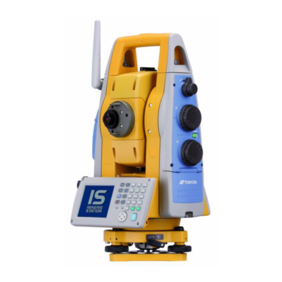
1 NOMENCLATURE AND FUNCTIONS NOMENCLATURE AND FUNCTIONS 1.1 Nomenclature Antenna (for Wireless LAN , SS Wireless) Sighting collimator Carrying handle Tracking indicator Camera(wide) Laser aperture (for Optical communication) Instrument center mark Objective lens/ Camera(telescope)/ Laser pointer Card cover Laser aperture Hardware reset switch (Inside the cover) Card cover lever... - Page 15 1 NOMENCLATURE AND FUNCTIONS Handle fixing screw Focus shuttle Focus jog Telescope grip Vertical shuttle Vertical jog Telescope eyepiece Instrument height mark Power switch Plate level Horizontal jog Horizontal shuttle Display window (With touch panel) Operation keys Battery cover Cover sensor (Inside the cover) Battery cover lever Circular level...
-
Page 16: Display
1 NOMENCLATURE AND FUNCTIONS 1.2 Display 1.2.1 Main Menu Contains The main menu contains as following items. Select the menu by pressing icons. Display icon PROGRAM MODE Setting a direction angle for backsight orientation • • Remote elevation measurement • Missing line measurement Repetition angle measurement •... -
Page 17: Measurement Menu
1 NOMENCLATURE AND FUNCTIONS 1.2.2 Measurement Menu Example : Distance Mode V-angle V : 88°44’25” H-angle HR : 169°48’45” Horizontal distance HD : 4.411m Relative elevation VD : 0.097m Operation keys 1.2.3 Display Marks Display Contents Display Contents V-angle Meter unit Percent grade Feet unit H-angle right... -
Page 18: Display Keys
1 NOMENCLATURE AND FUNCTIONS • The symbol marks for Auto-tracking and Auto-collimating Auto-collimating Auto-tracking (Laser is emitting) (Laser is emitting) The instrument is in auto-tracking The instrument is in auto-collimating status. status. Searching (Laser is emitting) Waiting (Laser is emitting) The instrument is searching a The instrument is in waiting status. -
Page 19: Backlight, Key Light Adjustment
1 NOMENCLATURE AND FUNCTIONS 1.3 Backlight, Key Light Adjustment 1.3.1 How to Adjust Reducing Time of Backlight To conserve battery power, this instrument would automatically turn the backlight off or reduce the backlight brightness by itself when it’s not in use. In addition, the instrument can control the backlight brightness automatically by an equipped illuminometer. - Page 20 1 NOMENCLATURE AND FUNCTIONS Press the time-menu down arrow to select the reducing time. Factory setting is ‘3 minutes' as default. Press the [OK] key on title bar. After that "Power Properties" screen will close automatically.
-
Page 21: Adjust The Backlight Brightness By Manual
1 NOMENCLATURE AND FUNCTIONS 1.3.2 Adjust the Backlight Brightness by Manual On the "Backlight" screen, please check it 'OFF' "An illuminometer is used.”. (Factory setting is 'ON' as default) The "Brightness adjusting slide bar” will be appeared on Display. Adjust the brightness by pressing [Dark-Bright] button. Press the [OK] key on title bar. -
Page 22: Selecting The Automatic Lighting Option
1 NOMENCLATURE AND FUNCTIONS 1.3.3 Selecting the Automatic Lighting Option On the "Backlight" screen, select a Radio button from “Automatic lighting” column. (Factory setting is “The light is switched on with an illuminometer.” as default) Press the [OK] key on title bar. After that "Power Properties" screen will close automatically. •... -
Page 23: Selecting The Key Light Option
1 NOMENCLATURE AND FUNCTIONS 1.3.4 Selecting the Key Light Option The Key Light option: [Key light is always off, Key light is always on, Key light synchronizes with backlight] Press the tab [Key Light]. You can see the "Key Light" screen on Display. Select a Radio button. -
Page 24: Ram Data Backup
1 NOMENCLATURE AND FUNCTIONS 1.4 RAM Data Backup If your device had not recharged during several days, the battery will be running down, and you would lose all of data on the device other than that in the "Internal Disk (internal micro SD card)". In addition, you might perform hardwarereset by the hardware problem or software problem. - Page 25 1 NOMENCLATURE AND FUNCTIONS Press the [YES] key. Backup function will start. Return to "RAM Backup" screen automatically, when the data back up has been completed. Press the [OK] key on title bar. After that "RAM Backup" screen will close automatically. •...
-
Page 26: Set The Automatic Backup For Every Suspension
1 NOMENCLATURE AND FUNCTIONS 1.4.2 Set the Automatic Backup for Every Suspension On the "RAM Backup" Screen, please check it 'ON' the "RAM data will be backed up before suspension.". (Factory setting is 'ON' as default) Press the [OK] key on title bar. After that, "RAM Backup" screen will close automatically. 1.4.3 Set the Restoration after Hardware Reset On the "RAM Backup"... -
Page 27: Hardware Reset
1 NOMENCLATURE AND FUNCTIONS 1.5 Hardware Reset If your instrument not responding or an application hangs, please try to perform a software reset first. Still, when useless, please perform hardware reset. You will lose all of data on the device other than that in the "Internal Disk" after hardware reset and will need to reinstall the applications and the data you install on your instrument. -
Page 28: Touch Panel Calibration
1 NOMENCLATURE AND FUNCTIONS 1.7 Touch Panel Calibration If your instrument is not responding properly to your taps, you may need to calibrate the touch panel. • How to calibrate the touch panel Press the icon [Start]-[Settings]-[Control Panel]- [Stylus]. You can see the "Stylus Properties" screen on Display. - Page 29 1 NOMENCLATURE AND FUNCTIONS Using the stylus pen, press the center of the targets on the screen. After pressing all targets (5 points), press the [ENT] key, or tap the display. Press the [OK] key. The display returns to previous menu.
-
Page 30: Operating Panel Key
1 NOMENCLATURE AND FUNCTIONS 1.8 Operating Panel Key To operate the keys on the screen, touch them lightly with either the accessory stylus pen or your finger. Use either the stylus pen or your finger. Do not use a ballpoint pen or a pencil. 1.8.1 Operating Key Microphone Light sensor... -
Page 31: Turning Off The Touch Panel Function
1 NOMENCLATURE AND FUNCTIONS 1.8.2 Turning OFF the Touch Panel Function To wipe away tarnish and dirt on the touch panel while the power is turned ON, you can shut down the touch panel function according to the following directions. Turning OFF the touch panel function. -
Page 32: Operation Key(Touch Panel)
1 NOMENCLATURE AND FUNCTIONS 1.10Operation Key(Touch panel) Functions can be switched using the operation keys at the bottom of the screen for each of the following modes. Angle measuring mode Page 1 Angle measuring mode Page 2 Angle measuring mode Page 3 Distance measuring mode Page 1 Distance measuring mode Page 2 Coordinate measuring mode Page 2... - Page 33 1 NOMENCLATURE AND FUNCTIONS Angle measuring mode Page Display Function 0SET Angle of horizontal is set to 0° 00'00". HOLD Holds the horizontal angle. HSET Sets the horizontal angle by input value. The function of operation keys on next page (P2). Sets the tilt function, ON/OFF.
-
Page 34: Star Key Mode
1 NOMENCLATURE AND FUNCTIONS 1.11Star Key Mode Press the star( ) key to view the instrument options. The following instrument options can be selected from the star key: Auto-tracking icon Auto-collimating icon Auto-Inversion icon Auto-tracking parameters set icon Signal level icon Electric circular level icon Point guide icon or Tracking indicator icon Focus icon... - Page 35 1 NOMENCLATURE AND FUNCTIONS • Tracking Indicator A man who is staying on line with the direction of IS series or automatic tracking status by emitted LED light (orange color) from IS series. Operation Pressing [Tracking indicator icon] on the screen. The tracking indicator status will be changed according to the type of auto tracking mode and its conditions.
- Page 36 1 NOMENCLATURE AND FUNCTIONS • Signal mode The light acceptance quantity level (Signal level) is displayed in this mode. When reflected light from the prism is received, a buzzer sounds. This function is good for easy collimation when the target is difficult to find. The received return signal level is displayed with bar graph as follows.
- Page 37 1 NOMENCLATURE AND FUNCTIONS • Laser Pointer ON/ON(blink)/OFF The laser pointer assists with collimation by radiating visible laser light from the objective lens to the target. The laser pointer can be used for the Prism, Non-prism and Non-prism long mode. Laser aperture Laser pointer will be OFF when auto-tracking or auto-collimation is ON.
-
Page 38: Switching Measurement Distance Modes
1 NOMENCLATURE AND FUNCTIONS 1.11.1Switching Measurement Distance Modes Pressing the [Prism / Non-prism / Non-prism long] icon displays the following screen. Each mode can be switched by using the buttons as shown below. • Setting Measurement distance range of ‘Non-prism long mode’ It is possible to measure long distance in the Non-prism Long mode. -
Page 39: Setting By Using Star Key
1 NOMENCLATURE AND FUNCTIONS 1.11.2Setting by Using Star Key [Example] : Switch on the laser pointer Turn the power switch on. Press the [ ] key. Press the [Laser pointer] icon. The laser pointer will be turned on. -
Page 40: Auto Power Off
1 NOMENCLATURE AND FUNCTIONS 1.12Auto Power Off To save battery power, the IS would automatically turn the power off (suspend) by itself when it’s not in use. You can adjust the settings of this function. How to adjust the settings of auto power off function •... - Page 41 1 NOMENCLATURE AND FUNCTIONS Press the [OK] key on title bar. After that "Power Properties" screen will close automatically. While on external power, the auto power off function can be enabled too. To set this function, please check it 'ON' the "Enable suspend while on external power” on the "Power Off "...
-
Page 42: Focus Function
1 NOMENCLATURE AND FUNCTIONS 1.13Focus Function The focus is adjusted with the manual or assist-focusing. 1.13.1Manual Focus Adjust the focus with focus jog / shuttle. Manual focusing will take precedence over assist-focusing. When using focus jog / shuttle during assist-focus mode, the assist-focus mode will end. Focus shuttle : If you rotate the shuttle through large angles, the focus changes quickly. -
Page 43: Setting Focus Function
1 NOMENCLATURE AND FUNCTIONS 1.13.3 Setting Focus Function [Example] • Assist focus Turn the power switch on. Press the [ ] key. Use the sighting collimator to aim the target roughly. Press the [MF] icon. The icon will change to [AF], and the instrument will enter assist focus mode. -
Page 44: Rotating Method
1 NOMENCLATURE AND FUNCTIONS 1.14Rotating Method This mark will appear while the instrument is rotating automatically. *1) 1.14.1Rotating by H/V Shuttle and H/V Jog H/V shuttle or H/V jog can be used to rotate the instrument manually. The shuttle movement or displacement is proportional in speed and size of angle desired. -
Page 45: Using Together With Rc-3 Remote Control System
Turn-round function You can turn the IS series round to the remote controller side easily by [Turn-round] key of the remote controller. This function helps to increase one man surveying efficiency. RC-3 See to 5 “PROGRAM MODE”... -
Page 46: Using Connecting With Personal Computer (Pc)
Rotating command Rotating of setting angle. Inversion Inversion movement. Action Setting from automatic tracking mode to Setting tracking mode each command mode. • Please refer to the IS Series Interface Manual (sold separately) for details about connection to the instrument. -
Page 47: Using The Usb Port
1 NOMENCLATURE AND FUNCTIONS 1.17Using the USB Port Type miniB (Active Sync) Type A (USB Memory) • Using ActiveSync For Type mini B, refer to Chapter 2.9 “Active Sync”. • Using a USB memory Open the USB connector cover. Insert a USB memory into the Type A side. Confirm that the USB memory has been recognized. -
Page 48: Preparation For Measurement
2 PREPARATION FOR MEASUREMENT PREPARATION FOR MEASUREMENT 2.1 Power Connection Obtain power from BT-65Q battery or an external battery. • When using the BT-65Q, leave the power of the instrument switched ON. External battery • Selecting an external battery When using an external battery, select the battery type, either “Li-ion” or “12V BATTERY.” Regarding operating procedures, refer to Chapter 6 “PARAMETERS SETTING MODE”... -
Page 49: Setting Instrument Up For Measurement
Mount the instrument to the tripod. Level and center the instrument precisely to insure the best performance. Use tripods with a tripod screw of 5/8 in. diameter and 11 threads per inch, such as the Type E TOPCON wide- frame wooden tripod. Reference: Leveling and Centering the Instrument 1. -
Page 50: Power Switch Key On
2 PREPARATION FOR MEASUREMENT 2.3 Power Switch Key ON Confirm the instrument is leveled. Turn the power switch ON. Progress bar will be displayed during reloading the Operating System, after you turn the instrument on at the first time or perform hardware reset. -
Page 51: Battery Power Remaining Display
2 PREPARATION FOR MEASUREMENT 2.4 Battery Power Remaining Display Battery power remaining display indicates the power condition. Battery Power Remaining Display Measurement is possible. The power is poor. The battery should be recharged or replaced with a fully charged battery. Measurement is impossible -- need to recharge or replaces the battery. -
Page 52: Vertical And Horizontal Angle Tilt Correction
2 PREPARATION FOR MEASUREMENT 2.5 Vertical and Horizontal Angle Tilt Correction When the tilt sensors are activated, automatic correction of vertical and horizontal angle for mislevelment is displayed. To ensure a precise angle measurement, tilt sensors must be turned on. The display can also be used to fine level the instrument. -
Page 53: Setting Tilt Correction By Operation Key
2 PREPARATION FOR MEASUREMENT 2.5.1 Setting Tilt Correction by Operation Key [Example] Setting Tilt OFF Press the [P1] key to get the page 2. Press the [TILT] key. Current setting is displayed. Press [OFF] key. Press [EXIT] key. The display returns previous mode. •... -
Page 54: Compensation Of Systematic Error Of Instrument
2 PREPARATION FOR MEASUREMENT 2.6 Compensation of Systematic Error of Instrument 1) Error of vertical axis (X,Y tilt sensor offset) 2) Collimation error 3) Error of vertical angle 0 datum 4) Error of horizontal axis The above mentioned errors can be compensated by software, which calculated internally according to each compensation value. -
Page 55: How To Enter Numerals And Alphabet Letters
2 PREPARATION FOR MEASUREMENT 2.7 How to Enter Numerals and Alphabet Letters This instrument supports two ways to enter numerals and alphabet letters. One is by physical(hardware) keyboard that is similar to cellular phone method. Three alphabet characters are assigned to one numeral key. The other is by using the software input panel. - Page 56 2 PREPARATION FOR MEASUREMENT Press the [ ] key to be entering alphabet letter mode. Alphabet letter mode indicator will be appeared on the task bar. Alphabet letter mode indicator Enter Alphabets. Input 'j', Press [4](JKL)key. then the sub window featuring 'j' character will appear on the display which indicate a entering character.
- Page 57 2 PREPARATION FOR MEASUREMENT Press the [ ] key to be returning numeric mode. Alphabet letter mode indicator will be disappeared on the task bar. Input ‘104’, Press [1], [0], [4]. Then ‘104’ will be appended after ‘job_’. Press the [ENT] key. In alphabet letter mode, [Shift] + [0-9,.-] keys perform uppercase character.
- Page 58 2 PREPARATION FOR MEASUREMENT • Invoke the software input panel. Press the [ ] key or press keyboard icon on the task bar and select “Keyboard” You can see the software input panel on display. You can input data as if you were typing on your PC keyboard.
-
Page 59: Data Memory Card
2 PREPARATION FOR MEASUREMENT 2.8 Data Memory Card How to insert a data memory card(CF card) • Card guide Card cover Data memory card Card cover lever Push up the card cover lever to open the card cover. Insert a data memory card. Please make sure you have the front and back of the CF cards facing correctly when inserting into the card slot. -
Page 60: Active Sync
2 PREPARATION FOR MEASUREMENT 2.9 Active Sync Microsoft ActiveSync is the data synchronization software: It synchronizes data between Windows CE devices (such as the IS) and PCs. Using ActiveSync, the IS can exchange data to a PC via USB cable. To establish a connection between the instrument and your PC, you first need to install ActiveSync in your PC. -
Page 61: Wireless Lan Function On/Off
2.12Inclination of Prism and Measuring Error For the best results, aim or point prisms in the direction of the IS series so that maximum signal can be returned to the instrument. Sighting prism obliquely because of inclined settings, may result in measuring errors. - Page 62 2 PREPARATION FOR MEASUREMENT • Prism type-2 (Normal prism) Distance Measuring error Angle measuring error Angle error Increasing range ( mm ) distance range ( mm ) C=30 C=30 C=40 C=40 Inclined angle (degree) Inclined angle (degree) • Prism type - 3 or 5 (Prism unit A2/A3/A6) Angle measuring error Distance Measuring error Angle error...
-
Page 63: Automatic Tracking / Automatic Collimation
3 AUTOMATIC TRACKING / AUTOMATIC COLLIMATION AUTOMATIC TRACKING / AUTOMATIC COLLIMATION WARNING • Cause eye injury or blindness. Do not stare into beam. CAUTION Let the laser beam reach the aimed object or the target without anybody else in the laser beam path. In •... -
Page 64: Automatic Tracking
3 AUTOMATIC TRACKING / AUTOMATIC COLLIMATION 3.1 Automatic Tracking The instrument will measure the moving target(prism) in automatic tracking mode. • It is possible to perform auto-tracking only in prism mode. When switched to the automatic tracking mode, it becomes prism mode from Non-prism mode/Non- prism long mode automatically. - Page 65 3 AUTOMATIC TRACKING / AUTOMATIC COLLIMATION • If the target prism is lost during auto tracking status, the instrument will automatically change to Waiting status. If the target is found during Waiting status, tracking resumes, and if not, status changes to Searching status.
-
Page 66: Automatic Collimation
3 AUTOMATIC TRACKING / AUTOMATIC COLLIMATION 3.2 Automatic Collimation The function enables the instrument to search and collimate automatically the center of the prism when the telescopic is aimed at a prism roughly. (in the range of approx. ±5°) Use this mode for the object which is stable. You can select Fine or Course mode for the distance measurement in auto-collimation. -
Page 67: Range Of Laser For Auto-Tracking And Auto-Collimating
3 AUTOMATIC TRACKING / AUTOMATIC COLLIMATION 3.3 Range of Laser for Auto-tracking and Auto-collimating The range of laser at the long distance is within ±30' as shown below. So you had better collimate the prism so that the prism may be located within this range of laser in the first step. As for it, rapid automatic collimating and automatic tracking becomes possible. -
Page 68: Setting Parameters For Auto-Tracking
Also it is enable to set each search pattern separately. WAIT TIME 0:00 to1:00:00 The time the prism is lost before IS series starts the searching. If the (1sec. step) mode is set to [HOLD], mode will not change to searching. HOLD... - Page 69 ±5° in both directions horizontal and vertical. 3) Wait Time The time the prism is lost before IS series starts the searching. Setting time is 1second step maximum 60 minutes. If the mode is set to [HOLD], mode will not change to searching.
-
Page 70: How To Set The Parameters
3 AUTOMATIC TRACKING / AUTOMATIC COLLIMATION 6) Prediction operating time After the instrument loses a prism, the time (prediction operation time) for the instrument to continue moving operation can be set up. During auto tracking operation, when auto tracking axis between the instrument and a prism is intercepted by a tree etc., the moving is continued supposing a motion (prediction) of the prism till then. -
Page 71: Standard Measurement Mode
4 STANDARD MEASUREMENT MODE STANDARD MEASUREMENT MODE STANDARD MEASUREMENT MODE Angle measurement, Distance measurement, Coordinate measurement . Press the [MEAS] icon. 4.1 Screen Displays In the standard measurement mode, the collimation screen is displayed on the display device except during collimation with the telescope. The images include a telescopic image and a wide-angle image. -
Page 72: Changing The Image's Magnification
4 STANDARD MEASUREMENT MODE 4.1.2 Changing the Image's Magnification ← When the [ ] cursor key is pressed, magnification decreases. → When the [ ] cursor key is pressed, magnification increases. Displays the current magnification. There are 4 magnifications: 0.5, 1.0, 2.0, 4.0 and 8.0 4.1.3 Adjusting the Image's Brightness ↑... -
Page 73: Switching The Cross-Hairs On And Off
4 STANDARD MEASUREMENT MODE 4.1.4 Switching the Cross-Hairs On and Off Each time numeric key [9] is pressed, the cross-hairs appear or disappear from the image. Each time the [9] key is pressed, the cross- hairs on the screen image will change. (Black/White/OFF) -
Page 74: Angle Measurement
4 STANDARD MEASUREMENT MODE 4.2 Angle Measurement 4.2.1 Measuring Horizontal Angle Right and Vertical Angle Make sure the mode is in angle measurement Collimate the 1st target (A). Set horizontal angle of target (A) at 0° 00' 00". Press the [0SET] key and the [YES] key. Collimate the 2nd target (B). -
Page 75: Switching Horizontal Angle Right/Left
4 STANDARD MEASUREMENT MODE 4.2.2 Switching Horizontal Angle Right/Left Make sure the mode is angle measurement. Press the [P1] key to get on the page 2. Press the [R/L] key. The mode Horizontal angle Right(HR) switches to angle Left(HL) mode. Measure the target in the same manner as HR mode. -
Page 76: Measuring From The Required Horizontal Angle
4 STANDARD MEASUREMENT MODE 4.2.3 Measuring from the Required Horizontal Angle 1) Setting by Holding the Angle Make sure the mode is angle measurement . Set the required horizontal angle, using Horizontal jog/shuttle. Example : 90°20'30" Press the [HOLD] key. Collimate the target.*1) Press the [YES] key to finish holding the horizontal angle. -
Page 77: Vertical Angle Percent Grade(%) Mode
4 STANDARD MEASUREMENT MODE 4.2.4 Vertical Angle Percent Grade(%) Mode Make sure the mode is angle measurement . Press the [P1] key to get on the page 2. Press the [V/%] key. *1) *1) Every time pressing the [V/%] key, the display mode switches. -
Page 78: Automatic Rotation To A Required Horizontal And Vertical Absolute Angle
4 STANDARD MEASUREMENT MODE 4.2.5 Automatic Rotation to a Required Horizontal and Vertical Absolute Angle The IS series can be rotated to a required horizontal and vertical absolute angle by direct key input. Example: Both vertical and horizontal angle At angle measuring mode (Page 3), press the [TURN] key. -
Page 79: Distance Measurement
Prism mode and Non-prism mode • In IS series, the distance measurement will be done using invisible pulse laser beam emitted from pulse laser diode. You can select measurement mode between Prism mode which collimating a prism and Non-prism mode, Non-prism long mode that is collimating a target object except prism. - Page 80 • Precautions for Use of Non-prism long mode IS series made non-prism measurement possible to reach the distance that had never been achieved before. In the non-prism long mode, the following attentions need to be paid because the farther the target object be, the weaker the reflection from the target and the larger the beam diameter become.
-
Page 81: Setting Of The Atmospheric Correction
4 STANDARD MEASUREMENT MODE 4.3.1 Setting of the Atmospheric Correction When setting the atmospheric correction, obtain the correction value by measuring the temperature and pressure. Setting the atmospheric correction, see Chapter 9 “SETTING ATMOSPHERIC CORRECTION” . 4.3.2 Setting of the Correction for Prism Constant Topcoat’s prism constant value is 0. - Page 82 4 STANDARD MEASUREMENT MODE Input the distance range by pressing the numeric key. *1) Example:10m Press the [ENTER] key. [ENTER] key The display returns to the star key mode. *1) Input range: 5 m - 1,800 m (17 ft. - 5,900 ft.)
-
Page 83: Distance Measurement (Continuous Measurement)
4 STANDARD MEASUREMENT MODE 4.3.4 Distance Measurement (Continuous Measurement) Make sure the mode displays angle measurement Collimate the center of prism. Press the [ ] key. *1),*2) [Example]: Horizontal distance / Relative elevation mode The result are shown.*3) ~ *7) *1)The following characters will be shown on the 4th line right hand of the display to represent measurement mode. -
Page 84: Distance Measurement (Single/N-Times Measurement)
4 STANDARD MEASUREMENT MODE 4.3.5 Distance Measurement (Single/N-times Measurement) When presetting the number of times, the instrument measures the distance as the setting times and the average distance will be displayed. When presetting the number of times as 1 or 0, it does not display the average distance, because of single measurement. -
Page 85: Fine / Coarse Measuring Mode
4 STANDARD MEASUREMENT MODE 4.3.6 Fine / Coarse Measuring Mode Prism Mode : This is a normal distance measuring mode. •Fine mode Measurement time 0.2mm mode : approx.3 seconds 1 mm mode : approx.1.2 seconds The unit to be displayed is 0.2mm or 1mm. (0.001ft or 0.005ft) •... -
Page 86: Stake Out (S.o)
4 STANDARD MEASUREMENT MODE • To select distance measurement mode Confirm the distance measurement mode Collimate the center of prism. Press the [MODE] key. The first letter of the current mode is displayed.*1) Select the measurement mode by pressing the [FINE], [cRS] or [CRS] key. - Page 87 4 STANDARD MEASUREMENT MODE [Example : Horizontal distance] Press the [P1] key in the distance measurement mode to get on page 2. Press the [S.O] key . The current setting value is displayed. With the [HD] - [SD] keys, select a mode for inputting the standard distance.
-
Page 88: Coordinate Measurement
4 STANDARD MEASUREMENT MODE 4.4 Coordinate Measurement 4.4.1 Setting Coordinate Values of Occupied Point Set the coordinates of instrument (occupied point) according to coordinate origin, and the instrument automatically converts and displays the unknown point (reflector point) coordinates following the origin. Reflector (n,e,z) Inst.Point C Origin(0,0,0) - Page 89 4 STANDARD MEASUREMENT MODE Press the [N] key. Input the N coord. Press the [SET] key.*1) Press the [E] key. Input the E coord. Press the [SET] key.*1) Press the [Z] key. Input the Z coord. Press the [SET] key.*1) Press the [EXIT] key.
-
Page 90: Setting Of The Instrument Height / Reflector(Prism) Height
4 STANDARD MEASUREMENT MODE 4.4.2 Setting of the Instrument Height / Reflector(Prism) Height Measure the coordinates by entering the instrument height / reflector height, coordinates of unknown point will be measured directly. [Example] : Instrument height Confirm the angle measurement mode. Press the [ ] key. -
Page 91: Execution Of Coordinate Measuring
4 STANDARD MEASUREMENT MODE 4.4.3 Execution of Coordinate Measuring Measure the coordinates by entering the instrument height and reflector height, coordinates of unknown point will be measured directly. When setting coordinate values of occupied point, see section 4.4.1“Setting Coordinate Values of •... -
Page 92: Data Output
4 STANDARD MEASUREMENT MODE 4.5 Data Output Result of measurement is transferred from the IS series to Data Collector. [Example: Distance measurement mode] With the SETUP mode, set the communication parameters. Refer to Chapter 6 “PARAMETERS SETTING MODE” . After setting the communication parameters, select the distance measurement mode. -
Page 93: Data Output By [Rec] Key
4 STANDARD MEASUREMENT MODE 4.6 Data Output by [REC] Key It is also possible to output the result of measurement by pressing the [REC] key . [Example: Distance measurement mode] With the SETUP mode, set the communication parameters. Refer to Chapter 6 “PARAMETERS SETTING MODE”... -
Page 94: Data Output Of Is Series
4 STANDARD MEASUREMENT MODE 4.7 Data output of IS series The information of IS series regarding tracking auto-tracking are added to the protocol of Topcon Total Station system so far. Also you can add utility information such as battery remaining, EDM mode, auto-tracking mode, normal/ reversed face information, Tilt information if you like. -
Page 95: Program Mode
5 PROGRAM MODE PROGRAM MODE Select the menu by pressing panel icon. Main menu Press the [PROG] icon. Program mode menu Edge abstraction mode Refer to Chapter 5.6 “Edge Abstraction Mode” . Repetition angle measurement Refer to Chapter 5.4 “Repetition Angle Measurement (REP)” . Missing line measurement Refer to Chapter 5.3 “Missing Line Measurement (MLM)”... -
Page 96: Setting A Direction Angle For Backsight Orientation(Bs)
5 PROGRAM MODE 5.1 Setting a Direction Angle for Backsight Orientation(BS) (Entering the instrument and backsight coordinate values) This program uses the input coordinate values of the occupied point, (instrument), and backsight point to calculate the backsight orientation direction angle. The occupied and backsight coordinate input display appears. - Page 97 5 PROGRAM MODE Input N and E coordinate of occupied point C. Example : N coordinate; 5.321m : E coordinate; 8.345m Input N and E coordinate of backsight point A. Example : N coordinate; 54.321m : E coordinate; 12.345m To memorize the occupied point, press the [SET OCC] key.
-
Page 98: Remote Elevation Measurement (Rem)
5 PROGRAM MODE 5.2 Remote Elevation Measurement (REM) The Remote Elevation program calculates the vertical distance (height) of a remote object relative to a prism and it's height from a ground point, (without a prism height). When using a prism height, the remote elevation measurement will start from the prism (reference point). - Page 99 5 PROGRAM MODE Press the [YES] key. Collimate prism. Press the [Meas Prism] key. Press the [SET] key. (To measure the distance again, press the [RE-TRY] key.) Collimate target K. Vertical angle(VA) and Vertical distance(VD) will be shown.
- Page 100 5 PROGRAM MODE 2)Without prism height input Press the [REM] icon. Select the [NO] button. Collimate prism. Press the [Meas Prism] key. Press the [SET] key. Collimate ground point G. Press the [Meas Ground] key. Press the [SET] key. Collimate target K. Vertical angle(VA) and Vertical distance(VD) will be shown.
-
Page 101: Missing Line Measurement (Mlm)
5 PROGRAM MODE 5.3 Missing Line Measurement (MLM) The Missing Line Measurement program calculates the horizontal distance (dHD), slope distance (dSD) and elevation (dVD) between two target prisms. The instruemt can accomplish this in two ways: MLM Method (A-B, A-C): Measurement is A-B, A-C, A-D, ..MLM Method (A-B, B-C): Measurement is A-B, B-C, C-D, .. - Page 102 5 PROGRAM MODE Collimate prism B, and press the [MEAS] key. Horizontal distance between the instrument and prism B will be shown. And then, the horizontal distance (dHD), relative elevation (dVD) and slope distance (dSD) between prism A and B will be shown. To measure the distance between points A and C, repeat procedure •...
-
Page 103: Repetition Angle Measurement (Rep)
5 PROGRAM MODE 5.4 Repetition Angle Measurement (REP) Repetition Angle Measurement program calculates horizontal angles and shows the total angle (Ht) and the mean (Hm) of all the angles measured. The program also keeps track of the amount of complete sets of horizontal angles measured. Repetition Angle Measurement program can be done by horizontal angle right measurement mode. - Page 104 5 PROGRAM MODE The total of angle and the mean of angle are shown. Repeat procedure to measure the desired number of repetitions. • Horizontal angle can be accumulated up to 99 times. To clear all data, press the [RESET] key. •...
-
Page 105: Ap-L1A Communication Emulator
5 PROGRAM MODE 5.5 AP-L1A Communication Emulator With IS Series, it is possible to execute AP-L1A communication emulation. Set up for use of remote control system is also done here. 5.5.1 Activate AP-L1A communication Emulator Press the [Ext.Link] icon. AP-L1A Communication Emulator program... -
Page 106: Setup For Communication
5 PROGRAM MODE 5.5.2 Setup for Communication This section describes how to set up parameters to execute communication. Example: Set up RC parameter Follow the steps described in “5.5.1 Activate AP-L1A communication Emulator” and activate AP-L1A communication emulator program [Ext.Link]. Press the [Setting] key. -
Page 107: Edge Abstraction Mode
5 PROGRAM MODE 5.6 Edge Abstraction Mode In this mode, the edges of structures and other objects whose distance cannot be directly measured are detected using image processing, and the coordinates are then easily measured. Press the [EDGE] icon. Collimate the target object. Switch to the telescopic mode and press the [MEAS] key. -
Page 108: Displayed Messages
To change them, press the [CLEAR] key. [Please specify within the limit.] Tap inside the frame. If message code still persist after attempting to clear them, contact your local Topcon dealer or • Topcon head office. -
Page 109: Parameters Setting Mode
6 PARAMETERS SETTING MODE PARAMETERS SETTING MODE PARAMETERS SETTING MODE In this mode, setting of parameters regard with measuring and communications will be done. When a parameter is changed and set, the new value is stored into the memory. -
Page 110: Parameter Setting Options
6 PARAMETERS SETTING MODE 6.1 Parameter Setting Options 6.1.1 Measurement Factory default settings are indicated with underlines. Menu Selecting Item Contents MEASUREMENT1 MINI ANG READING NORM / MINI Select the minimum display angle reading unit. FINE READING 1mm / 0.2mm Select 1mm/0.2mm for the minimum distance in fine mode. -
Page 111: Communication
6 PARAMETERS SETTING MODE 6.1.2 Communication Factory default settings are indicated with underlines. Menu Selecting Item Contents COMMON PARAMETER RS232C/SSWireless/ RECKey Data Out Select communication route for REC key data output. Bluetooth Select to record coordinates in standard or 11 digits with raw STANDARD/WITH NEZ REC FORM data. -
Page 112: Value Input
6 PARAMETERS SETTING MODE Bluetooth Select the option OFF or ON for carriage return and line feed CR, LF OFF/ON when collecting measurement data with a computer. [PIN CODE]: Setting between 0~9999 (Factory default setting:1111) [PIN CODE]/ PIN CODE SET [PIN CODE [PIN CODE CHECK OFF/ON] CHECK OFF/ON]... -
Page 113: Setting Parameters
6 PARAMETERS SETTING MODE 6.2 Setting Parameters [Example setting] S/A BUZZER: OFF Press the [SETUP] icon. Press the [MEASUREMENT] key. Press the [MEASUREMENT1] key. Press the [NEXT] key three times. Select the [OFF] button of S/A BUZZER.*1) When the [SET] key is pressed, the setting will be set and the SETUP MODE screen will reappear. -
Page 114: Check And Adjustment
If the difference of the prism mode and non-prism mode is the range of ±10mm even one time, the instrument is normal. If the difference is never the range of ±10mm, contact TOPCON or your TOPCON dealer. Non-prism long mode 1) Set a prism 30 to 50 meter apart from the instrument and measure the distance to the prism by prism mode. -
Page 115: Checking The Optical Axis
To check if the optical axis of EDM and theodolite are matched, follow the procedure below. It is especially important to check after adjustment of the eyepiece reticle is carried out. Position a prism about 50 to 100m apart from IS series. Press the [ADJUST] icon. Press the [EDM CHECK] key. - Page 116 7 CHECK AND ADJUSTMENT • H direction confirmation (Do not move V direction). Turn the horizon jog counter clockwise, move the collimating point to the left side of prism gradually until buzzer sound stops. Prism Reticle Turn the horizontal jog clockwise slowly, and move the collimating point to the prism center gradually until at the position buzzer starts.
- Page 117 90°08'30" Reading to prism center 90°08'50" Difference 20" If the difference is more than mentioned value, contact with your Topcon dealer or Topcon. For non-prism mode • If the instrument is in the hold mode, press the [HOLD] key to release the hold mode.
- Page 118 Repeat the previous procedure 6 to 14 in the same way in the non-prism mode. If the difference is within 2', no problem for use. If the difference is more than mentioned value, contact with your Topcon dealer or Topcon.
-
Page 119: Checking The Optical Axis Of Laser Pointer
7 CHECK AND ADJUSTMENT 7.2.2 Checking the optical axis of Laser pointer Check whether the optical axis of the laser pointer coincides with the optical axis of the telescope by carrying out the following steps. The laser pointer indicates the approximate collimation position of the telescope. It does not indicate the exact collimation position. - Page 120 7 CHECK AND ADJUSTMENT About30 ° The direction of the laser pointer About30 ° As seen from above Adjustment screws When screws A, B and C are turned clockwise (the direction for tightening them), the laser pointer, as seen on the target from the standpoint of the IS, will move in the direction shown in the drawing. •...
-
Page 121: Inspection And Adjustment Of Optic Axis For Auto -Tracking
Normal position and telescope is shifted • Position a prism around 0 in horizontal and more than 100m (328ft) apart from the IS series. • Take care not to be interrupted the optical path during measurement. Press the [ADJUST] icon. - Page 122 7 CHECK AND ADJUSTMENT Measurement will begin. After the measurement is completed at the normal position, press the [TURN] key. Reverse and turn the telescope and instrument. Operate the H/V jog shuttle and collimate prism center with telescope. Press the [MEAS] key. Measured data will be checked inside the instrument, and the amount of deviation between vertical and horizontal directions of...
-
Page 123: Checking/Adjusting Each Function
7 CHECK AND ADJUSTMENT 7.3 Checking/Adjusting Each Function • Pointers on the Adjustment 1) Adjust the eyepiece of the telescope properly prior to any checking operation which involves sighting through the telescope. Remember to focus properly, with parallax completely eliminated. 2) Carry out the adjustments in the order of item numbers, as the adjustments are dependent one upon another. -
Page 124: Checking /Adjusting The Plate Level
7 CHECK AND ADJUSTMENT 7.3.1 Checking /Adjusting the Plate Level Adjustment is required if the axis of the plate level is not perpendicular to the vertical axis. • Check 1) Place the plate level parallel to a line running through the centers of two leveling screws, say, A and B. -
Page 125: Adjustment Of The Vertical Cross-Hair
7 CHECK AND ADJUSTMENT 7.3.3 Adjustment of the Vertical Cross-hair Adjustment is required if the vertical cross-hair is not in a place perpendicular to the horizontal axis of the telescope ( since it must be possible to use any point on the hair for measuring horizontal angles or running lines). -
Page 126: Collimation Of The Instrument
7 CHECK AND ADJUSTMENT 7.3.4 Collimation of the Instrument Collimation is required to make the line of sight of the telescope perpendicular to the horizontal axis of the instrument, otherwise, it will not be possible to extend a straight line by direct means. Check •... -
Page 127: Checking/Adjusting The Cross-Hairs On Telescopic/Wide-Angle Images
7 CHECK AND ADJUSTMENT 7.3.5 Checking/Adjusting the Cross-Hairs on Telescopic/Wide-angle Images Checking telescopic Image • Level the instrument with the plate level. With the telescope, collimate target point A, located at a distance of at least 15 meters. Check that the telescopic image (magnification of 4) is displayed. - Page 128 * In case you go beyond the adjustment range, WIDE: Wide angle a message to that effect will be displayed. In Magnification such a case, please contact TOPCON or your local Topcon dealer. Explanation of Keys [W/T] key : Switches between wide-angle and telescopic.
-
Page 129: Checking / Adjusting The Optical Plummet Telescope
7 CHECK AND ADJUSTMENT 7.3.6 Checking / Adjusting the Optical Plummet Telescope Adjustment is required to make the line of sight of the optical plummet telescope coincide with the vertical axis ( otherwise the vertical axis will not be in the true vertical when the instrument is optically plumbed). -
Page 130: Adjustment Of Vertical Angle 0 Datum
7 CHECK AND ADJUSTMENT 7.3.7 Adjustment of Vertical Angle 0 Datum If when measuring the vertical angle of target A at telescope position normal (direct) and reverse settings, the amount of normal and reverse measurements combined is other than 360° (ZENITH-0), half of the difference from 360°... -
Page 131: How To Set The Instrument Constant Value
7 CHECK AND ADJUSTMENT 7.4 How to Set the Instrument Constant Value To set the Instrument constant which is obtained in section 7.1“Checking and Adjusting of Instrument Constant” , follow as below. Press the [ADJUST] icon from the main menu. Press the [INST. -
Page 132: Compensation Systematic Error Of Instrument
7 CHECK AND ADJUSTMENT 7.5 Compensation Systematic Error of Instrument 7.5.1 Adjustment of Compensation Systematic Error of Instrument 1) Error of vertical axis (X,Y tilt sensor offset) 2) Collimation error 3) Error of vertical angle 0 datum 4) Error of horizontal axis The above mentioned errors will be compensated by software, which calculated internally according to each compensation value. - Page 133 7 CHECK AND ADJUSTMENT Turn the telescope in reverse telescope setting. Collimate target A. Press the [SET] key ten times. The number of measurements is displayed at the top right of the display. Collimate target B (more than ±10 ° from the level) in reverse telescope setting.
-
Page 134: Showing Compensation Systematic Error Of Instrument
7 CHECK AND ADJUSTMENT 7.5.2 Showing Compensation Systematic Error of Instrument Press the [ADJUST] icon from the main menu. Press the [3AXIS COMPENSATION] key. Press the [CONSTANT DISPLAY] key. Press the [EXIT] key. The display returns to previous menu. -
Page 135: Self Checking Mode
7 CHECK AND ADJUSTMENT 7.6 Self Checking Mode • Self checking option The self checking function is to check internal communication and tilt sensor offset value. When ambient temperature is changed or the instrument is not balanced by its internal battery is attached or detached, the self checking is recommended. - Page 136 7 CHECK AND ADJUSTMENT The instrument will turn automatically and the tilt sensor offset value will be measured and memorized. To cancel turning the instrument, press [EXIT] key. After checking, the ADJUST MPDE menu will be shown.
-
Page 137: Setting The Prism / Non-Prism Constant Correction Value
SETTING THE PRISM / NON-PRISM CONSTANT CORRECTION VALUE The prism constant value of Topcon is set to zero. When using prisms other than Topcon’s, it is necessary to set the prism constant correction value of that specific prism. Once you set the correction value for prism constant, it is retained after power is OFF. - Page 138 8 SETTING THE PRISM / NON-PRISM CONSTANT CORRECTION VALUE There are two ways to enter a prism constant correction value as described below: [ENTER] key [Directly entering the prism constant correction value] Press the prism selection switch and select [Manual]. Enter the prism constant correction value.
-
Page 139: Setting Atmospheric Correction
9 SETTING ATMOSPHERIC CORRECTION SETTING ATMOSPHERIC CORRECTION The velocity of light through air is not constant and depends on the atmospheric temperature and pressure. The atmospheric correction system of this instrument corrects automatically when the correction value is set. 15 ° C/59 ° F, and 1013.25hPa / 760mmHg / 29.9 inHg is as a standard value for 0ppm in this instrument. -
Page 140: Setting Of Atmospheric Correction Value
9 SETTING ATMOSPHERIC CORRECTION 9.2 Setting of Atmospheric Correction Value • How to Set Temperature and Pressure Value Directly Measure the temperature and air pressure surrounding the instrument beforehand. • Example : Temperature: +15°C, Pressure:1013.3 hPa Turn the power switch on. Press the [ ] key. - Page 141 9 SETTING ATMOSPHERIC CORRECTION • How to Set the Atmospheric Correction Value Directly Measure the temperature and air pressure to find atmospheric correction value(PPM) from the chart or correction formula. Turn the power switch on. Press the [ ] key. Press the [Prism constant value, Atmospheric correction] icon.
- Page 142 9 SETTING ATMOSPHERIC CORRECTION Atmospheric Correction Chart (For your reference) The atmospheric correction value is obtained easily with the atmospheric correction chart. Find the measured temperature in horizontal, and pressure in vertical on the chart. Read the value from the diagonal line, which represents the required atmospheric correction value. Example: The measured temperature is +26°C The measured pressure is 1014 hPa...
- Page 143 9 SETTING ATMOSPHERIC CORRECTION...
- Page 144 9 SETTING ATMOSPHERIC CORRECTION...
-
Page 145: Correction For Refraction And Earth Curvature
10 CORRECTION FOR REFRACTION AND EARTH CURVATURE CORRECTION FOR REFRACTION AND EARTH CURVATURE The instrument measures distance, taking into account correction for refraction and earth curvature. 10.1Distance Calculation Formula Distance Calculation Formula; with correction for refraction and earth curvature taken into account. Follow the Formula below for converting horizontal and vertical distances. -
Page 146: Power Source And Charging
11 POWER SOURCE AND CHARGING POWER SOURCE AND CHARGING 11.1On-board Battery BT-65Q To remove • Pull the battery cover lever and open the battery cover. Remove the battery. POWER LED CHARGE LED BC-30D Battery cover lever AD-12 AC-cable BT-65Q • To charge Connect the AC/DC converter AD-12 and AC-Cable to the charger. - Page 147 11 POWER SOURCE AND CHARGING Do not charge continuously, otherwise the battery and the charger may be deteriorated. • If charging is necessary, use the charger after stopping charge for approximately 30 minutes. • Do not charge the battery in right after the battery is charged, it causes deterioration of the battery in rare cases.
-
Page 148: Detach/Attach Of Tribrach
12 DETACH/ATTACH OF TRIBRACH DETACH/ATTACH OF TRIBRACH The instrument is easily detached or attached to the tribrach. Tribrach fixing screw Tribrach alignment groove Securing screw Tribrach fixing lever Alignment piece Tribrach alignment groove • Detachment 1) Loosen the tribrach fixing screw. 2) Loosen the tribrach fixing lever by turning counterclockwise. -
Page 149: Special Accessories
RC-3H RC-3R Remote Control System RC-3 Using together with RC-3R makes it possible to optical communication between the IS series and RC- 3R. This gives easy operation for one man surveying. Tribrach TR-5 Optical plummet tribrach TR-5P This is detachable tribrach having tribrach fixing This is detachable tribrach having built-in optical screw. - Page 150 13 SPECIAL ACCESSORIES Prism unit case, Model 6 Prism unit case, Model 3 Fixed 9 prisms unit or tilting 3 prisms unit can be This is the plastic case to store and carry various stored in this case. Especially, this is a very easy case sets of prisms.
-
Page 151: Battery System
In case of On-board battery In case of External battery External battery connector BT-65Q IS series Charging Charging time Charger Battery Quick charge for AC100V-240V use Approx. 5h BT-65Q BC-30D Note: Use batteries made by Topcon. Use of other batteries will cause malfunction. -
Page 152: Prism System
fixing screws. Plug 3 is necessary for the tribrach adaptor-2, tribrach adaptor-S2 and pole adaptor-F2 to coincide with the height of IS series. TR-5 or TR-5P tribrach should be used for prism side when the traverse surveys is performed. -
Page 153: Precautions
11) Even if any abnormality occurs, never attempt to disassemble or lubricate the instrument yourself. Always consult with TOPCON or your dealer. 12) To remove the dust on the case, never use thinner or benzine. Use a clean cloth moistened with neutral detergent. -
Page 154: Message/Error Displays
17 MESSAGE/ERROR DISPLAYS MESSAGE/ERROR DISPLAYS 17.1Message Message code Description Countermeasures No value was entered at time of Please Input Value! Input numerical value. numerical value input. A value outside permissible range was Please Input Exact Value! Input exact numerical value. input at time of numerical value input. -
Page 155: Error
17 MESSAGE/ERROR DISPLAYS 17.2Error Error code Description Countermeasures Data Read Error 01 to 27 The data could not be loaded. Close the program and restart the in- Data Set Error 01 to 17 The data could not be set. strument. If this error code continues to be dis- EDM Offset Read Error The EDM offset could not be loaded. - Page 156 Bluetooth security get error Bluetooth security set error There is no response from Bluetooth module There is no response from SSWireless module If error still persist after attempting to clear them, contact your local Topcon dealer or Topcon head • office.
-
Page 157: Specifications
18 SPECIFICATIONS SPECIFICATIONS Telescope Length : 165mm Objective lens : 45mm (EDM 50mm) : 30 × Magnification Image : Erect Field of view : 1°30' Resolving power : 3" Minimum focus : 1.4m Reticle illumination : Provided Assist Focus Method : Distance focus method or Contrat pack detection method Focus area... - Page 158 18 SPECIFICATIONS Manual Driving Maximum rotating speed * : 85° /sec Coarse movement : Shuttle driving (in 7 steps) Fine movement : Jog driving (minimum step about 1 second) : 0 ° ≤ HR < +360 ° Driving range * By reverse, rotating instruction Distance measurement Measurement range •...
- Page 159 18 SPECIFICATIONS Measurement accuracy/Least Count in Measurement/Measurement Time • Prism mode Measuring distance Measurement Least Count Measurement mode Measurement accuracy *1) in Measurement Time 0.2mm Approx. 3 sec. 0.2mm mode (0.001ft) (Initial 4 sec.) Fine ± (2mm +2ppm x D) m.s.e. Approx.
- Page 160 18 SPECIFICATIONS Electronic Angle Measurement Method : Absolute reading Detecting system : Horizontal : 2 sides Vertical : 2 sides Minimum reading : 1"/0.5" (0.2mgon/0.1mgon, 5mmil/2mmil) reading : 5"/1" (1mgon/0.2mgon, 20mmil/ 5mmil) reading : 5"/1" (1mgon/0.2mgon, 20mmil/ 5mmil) reading Accuracy(Standard deviation based on DIN 18723) : 1"...
- Page 161 Angle measurement and Distance measurement : Approx. 3.5 hours*2) *1) Continuous double face observations using automatic collimation *2) When not using wireless LAN and SS wireless Battery using time will vary depending on environmental conditions and operations done with • IS series.
- Page 162 18 SPECIFICATIONS Battery Charger BC-30D (with AC/DC converter AD-12 and AC-cable) Input voltage : AC 100-240V Frequency : 50/60Hz Recharging time (at +20°C /+68°F) Battery BT-65Q : 5 hours/1 battery Operating temperature : +10°C to +40°C ( +50°F to 104°F) Charging signal : Orange charge lamp should glow Finishing signal...
-
Page 163: Appendix
APPENDIX APPENDIX Dual Axis Compensation Inclination of the vertical axis with respect to true vertical will result in incorrectly measured horizontal angles. The extent of the error in horizontal angle measurement due to axis tilt depends on three factors : •... - Page 164 APPENDIX It is clear from the table that dual axis compensation has the most benefit when the elevation of the target is greater then 30° and the axis is tilted more than 10". The entries indicated in bold in the table show, in fact, that for many common surveying applications i.e.
-
Page 165: Index
20 INDEX INDEX Software Reset Stake Out (S.O) Star Key Mode Automatic Collimation Task Manager Automatic Tracking Touch Panel Calibration Active Sync Tracking Indicator Angle Measurement TRIBRACH Angle measuring mode Auto Power Off Automatic Vertical Angle Percent Grade(%) Mode BATTERY SYSTEM Backlight Adjustment Battery Power Remaining Display CHARGING... - Page 166 Address: 75-1, Hasunuma-cho, Itabashi-ku, Tokyo, 174-8580 JAPAN Country: JAPAN U.S.A. Representative Responsible party: TOPCON POSITIONING SYSTEMS,INC. Address: 7400 National Drive Livermore, CA94551, U.S.A Telephone number: 925-245-8300 Means of conformity This device complies with part 15 of the FCC Rules, Operation is subject to the following two conditions: (1) This device may not cause harmful interference, and (2) this device must accept any interference received, including interference that may cause undesired operation.
- Page 167 Community of Europe Compliance We, Topcon Corporation, declare EC Conformity for the following products: Product Identification: Brand: TOPCON Model/Type: Manufacturer: Name: TOPCON CORPORATION Address: 75-1, Hasunuma-cho, Itabashi-ku, TOKYO, 174-8580 Country: JAPAN Tel: 03-3558-2579 Fax: 03-3966-0038 Standards used: EN 60950-1: 2006 EN 300 328 V1.7.1...
- Page 168 ® ® ® Bluetooth and the Bluetooth logos are trademarks owned by Bluetooth SIG, Inc., USA and licensed to Topcon Corporation.
- Page 170 TOPCON CORPORATION 75-1 Hasunuma-cho, Itabashi-ku, Tokyo 174-8580, Japan www.topcon.co.jp 2008 TOPCON CORPORATION ALL RIGHTS RESERVED...
Need help?
Do you have a question about the IS Series and is the answer not in the manual?
Questions and answers