Table of Contents
Advertisement
Quick Links
Advertisement
Table of Contents

Related Manuals for Topcon IM-1000


Summary of Contents for Topcon IM-1000
- Page 1 INSTRUCTION MANUAL LUMINANCE METER Rev 1.1...
-
Page 3: Introduction
Thank you so much for your purchasing our TOPCON TECHNOHOUSE Luminance Meter IM-1000. IM-1000 is a handy type luminance meter that can measure a wide range with high accuracy. This manual describes the outline, basic operation procedure, specifications and the communication specifications required for developing the software regarding the Luminance Meter IM-1000. -
Page 4: Display For Safe Use
DISPLAY FOR SAFE USE In order to encourage the safe use of products and prevent any danger to the operator and others or damage to existing facilities, important warnings are put on the products and inserted into the instruction manuals. We suggest that everyone understand the meaning of the following displays and icons before reading the "SAFETY CAUTIONS"... - Page 5 If an abnormal noise, smell or smoke comes in this instrument, turn off the power and remove the AC adapter from the outlet at once. A fire will occur if using the instrument without repairing the Mandatory Action troublepoint. Consult with your dealer or TOPCON TECHNOHOUSE. CAUTION Icons Prevention Item Install the battery to be fit to the specified polarity.
- Page 6 • TOPCON shall not take any responsibility for damage derived from the inability to use this equipment, such as a loss of business profit and suspension of business.
- Page 7 USER MAINTENANCE Unless specified in this manual, the maintenance work shall be conducted only by a trained service engineer, to ensure the safety and performance of the instrument. The following maintenance work, however, may be executed by the operator. Regarding the maintenance method, read the applicable text in this manual.
-
Page 8: Table Of Contents
CONTENTS INTRODUCTION ........................3 DISPLAY FOR SAFE USE ......................4 1.PREPARATION BEFORE USE .................. 12 1.1. CHECKING THE INSTRUMENT AND ACCESSORIES ........... 12 1.2. NAMES AND FUNCTIONS OF COMPONENTS .............. 13 1.2.1. Names and functions of switches on keyboard ..................15 1.2.2. -
Page 9: Error Code
3.2.19. Setting the back light ..........................34 3.2.20. Setting the measurement data automatic saving function ................34 3.2.21. Setting the measurement data history clearing function .................. 34 4. COMMUNICATION WITH PERSONAL COMPUTER ..........35 4.1. COMMUNICATION COMMAND ..................35 4.2. COMMAND LIST ......................35 4.3. - Page 10 5.1. ERROR CODE LIST ......................56 APPENDICES ......................... 58 SPECIFICATIONS & PERFORMANCE .................. 58 BLOCK DIAGRAM ........................61 EXTERNAL DIMENSIONS DIAGRAM ..................62 GRAPH ........................... 63...
- Page 11 RULES OF SYMBOLS IN THIS MANUAL This manual has the rules about symbols as shown below. Symbol Description ☞ Shows the section to which you should make reference in this manual. “ ” ☞ < > Shows other manuals to which you should make reference. Explains the points that you should understand and pay attention to.
-
Page 12: 1.Preparation Before Use
1.PREPARATION BEFORE USE 1.1. CHECKING THE INSTRUMENT AND ACCESSORIES Make sure that you have the instrument and accessories shown below. If one of them is missing, contact your dealer or TOPCON TECHNOHOUSE. n IM-1000 instrument body n CD-ROM (Instruction manual/colorimetry program CS-900A) -
Page 13: Names And Functions Of Components
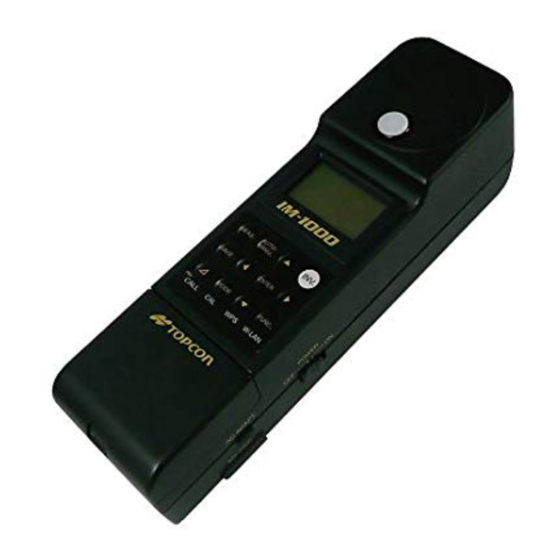
1.2. NAMES AND FUNCTIONS OF COMPONENTS This chapter will explain the names and functions of the components with the illustrations about the instrument. ○ Beam detector ○ Display unit ○ Keyboard Battery cover ○ Power switch ○ External power supply connector ○... - Page 14 The falling-off prevention hand strap is attached here. ○ Tripod screw: This screw is used to mount the instrument on the tripod. TOPCON TECHNOHOUSE has adopted the screw for mounting the 1/4-20UNC (depth: 5mm) camera. ○ Tool screw: This screw is used to mount the instrument on a system or others.
-
Page 15: Names And Functions Of Switches On Keyboard
1.2.1. Names and functions of switches on keyboard The names and functions of switches on the keyboard are mentioned below. AUTO/ INV. MEAS. MANU. SAVE. ENTER ⊿ MODE FUNC. INV. CALL W-LAN Name Function MEAS. switch Starts/stops measurement. When continuous measurement is valid, measurement starts by pressing this switch once and stops by pressing it again. - Page 16 ENTER switch This is used to decide the item, value, digit position, etc. in the function mode. ∆ switch Measurement is done in the difference mode. The difference against the reference value is indicated as the measurement data. MODE. switch Select the display mode.
-
Page 17: Names And Contents Of Data On The Display Screen
1.2.2. Names and contents of data on the display screen The names and contents of data on the display screen are mentioned below. Name Contents ○ Measurement Indicates the measurement range mode which is currently set. FL/FS/AJ/ML range mode ☞ “1.2.1. -
Page 18: Preparation
1.3. PREPARATION This chapter will explain the preparation before starting measurement. 1.3.1. Connecting the AC adapter How to connect the AC adapter to the instrument is mentioned below. Use the AC adapter which is an accessory sold separately. If not, the AC adapter malfunctions to cause a fire or electric shock. WARNING Remove dust or water from the outlet of the AC adapter. - Page 19 Insert the output connector of the AC adapter into the external power supply connector of the instrument. Insert the AC adapter plug into the outlet.
-
Page 20: Installing The Batteries
1.3.2. Installing the batteries How to install the batteries is mentioned below. Use the standard accessory, nickel hydride battery (charging type: 4 pieces). Use the standard accessory, nickel hydride battery (charging type). If you use others except the standard accessory, the instrument may operate irregularly. NOTICE MEMO For charging the nickel hydride battery, refer to the instruction manual of the charger. -
Page 21: Installing Personal Computer
1.3.3. Installing personal computer To connect a personal computer with the instrument, use the RS-232C cable exclusively for the instrument or the wireless LAN. The RS-232C signal line of the instrument is arranged according to the 9-pin D-SUB that is used in the DOS/V personal computer and others. When connecting with a personal computer through the extension cable, use the straight wiring cable. -
Page 22: Turning On/Off The Power
1.3.4. Turning ON/OFF the power How to turn on/off the power is mentioned below. n When turning on the power Slide the power switch to “ON”. When the power is turned on, initialization starts. If an error occurs during the initialization, the error message is indicated on the display unit. -
Page 23: 2.Operation Of The Measured Value
2.OPERATION OF THE MEASURED VALUE 2.1. DISPLAY OF THE MEASURED VALUE You can change the measured value display mode by pressing the [MODE] switch when measurement stops. The changeable display modes are shown below. Illuminance Ev/Chromaticity xy mode Illuminance Ev/Chromaticity u’v’ mode Tristimulus values XYZ mode Illuminance Ev/Correlated color temperature Tcp/Deviation duv mode... -
Page 24: Setting Operation
3. SETTING OPERATION 3.1. FUNCTION MODE Function mode is used to check and change a lot of data and items stored in the built-in memory of the instrument. 3.1.1. Shifting to function mode/returning to measurement mode Use the [FUNC.] switch to shift to the function mode and return to the measurement mode. Press the [FUNC.] switch once, and the system shifts to the function mode. -
Page 25: Set Item/Data Display
3.1.2. Set item/Data display In the function mode, the displayed items and data are changed by pressing the [ ] and [ ] switches. The set items and data are shown below. • Setting the averaging count ☞ “3.2.1. Setting the averaging count” •... -
Page 26: Details Of Function Mode
3.2. DETAILS OF FUNCTION MODE To select a proper item, use the [ ] and [ ] switches. To enter a numerical value, specify the digit position with the [ ] and [ ] switches and set a value with the [ ] and [ ] switches. -
Page 27: Setting The Interval Measurement Conditions
3.2.3. Setting the interval measurement conditions Set the start delay time, the count and the interval time for interval measurement. START : Set the time until measurement starts since you pressed the [MEAS.] switch. Settable range: 1 - 180s COUNT : Set the interval measurement count. Settable range: 1 - 50 TIME : Set the interval time. -
Page 28: Setting The Reference Light Source
3.2.6. Setting the reference light source Set the type of the reference light that will be applied to the calculation of color rendering property evaluation. Settable range : JIS Z 8726/Illuminant A/Illuminant D65/Illuminant D50/Illuminant D55/Illuminant D75/Illuminant C 3.2.7. Setting the sample light source Set the sample light source that will be applied to the calculation of color rendering property evaluation. -
Page 29: Setting The Spectral Correction
3.2.9. Setting the spectral correction Set whether the correction factor of each wavelength should be applied to the spectral radiation illuminance. Enter the correction factor directly or set it within 380nm - 780nm at intervals of 1nm through the remote mode. : Spectral correction is not applied. -
Page 30: Setting The Wireless Lan
3.2.11. Setting the wireless LAN Set ON/OFF of the wireless LAN function. MEMO • This menu is indicated only in the model having the wireless LAN function. • After changing the setting, turn on/off the power of the instrument. By turning it on/off, the set data is applied. -
Page 31: Setting The Wireless Lan Subnet Mask
3.2.13. Setting the wireless LAN subnet mask Set the instrument’s subnet mask that will be applied to the wireless LAN communication. Settable range : 255.255.0.0. - 255.255.255.255 MEMO • This menu is indicated only in the model having the wireless LAN function. •... -
Page 32: Setting The Wireless Lan Access Point
3.2.15. Setting the wireless LAN access point Set the access point (SSID) that will be applied to the wireless LAN communication. Press the [ENTER] switch, and the access points, which can be connected currently, are indicated. Select and decide a proper access point. MEMO •... -
Page 33: Setting The Wireless Lan Pass Phrase
3.2.17. Setting the wireless LAN PASS PHRASE Set PASS PHRASE that will be applied to the wireless LAN communication. Settable range : 63 letters or less MEMO • For setting PASS PHRASE, read the instruction manual of the connected device at the same time. -
Page 34: Setting The Back Light
3.2.19. Setting the back light Set ON/OFF of the back light in the liquid crystal display unit. : The back light is always OFF. : The back light is always ON. : When measurement is being done and when the instrument is not operated for 1 minute or more, the back light is OFF. -
Page 35: Communication With Personal Computer
4. COMMUNICATION WITH PERSONAL COMPUTER 4.1. COMMUNICATION COMMAND The instrument (IM-1000) can communicate with a personal computer by using RS-232C and wireless LAN. This chapter will explain the commands that will be used when the customer makes a peculiar program for the communication with the instrument. - Page 36 Communication command Function Start continuous measurement. The data of each measurement is not sent back. Obtain the measurement data with the “STR*” command. If you send this command during continuous measurement, “NO” is returned. Stop continuous measurement. If you send this command during continuous measurement, continuous measurement stops.
- Page 37 Communication command Function FW_#_####### Set the spectral correction factor (within 380 - 780nm at intervals of 1nm). 0: 380nm - 400: 780nm Settable range: 0.0001 - 100.0 FR_# Obtain the spectral correction factor (within 380 - 780nm at intervals of 1nm). 0: 380nm - 400: 780nm TRW_# Set ON/OFF of the tristimulus values.
-
Page 38: Communication Protocol
4.3. COMMUNICATION PROTOCOL The protocols for the RS-232C/wireless LAN communication are shown below. The instrument (IM-1000) sends the following answers as the responses to all the commands. • “OK” when the command is normally received • “NO” when the command cannot be analyzed •... -
Page 39: Ver Command
4.3.4. VER command Obtain the software version. Obtainable range: 1.00 - 99.99 External control device Command IM-1000 “VER”+CR+LF “OK”+CR+LF “1.00”+CR+LF “END”+CR+LF 4.3.5. SRL command Obtain the serial number. Obtainable range: 00000000 - 99999999 External control device Command IM-1000 “SRL”+CR+LF “OK”+CR+LF “12345678”+CR+LF... -
Page 40: St Command
“NG” with CR and LF is sent back. When the external control device receives “NG”, it sends “ERR” with CR and LF and you can check the contents of the error. External control device Command IM-1000 “ST”+CR+LF “OK”+CR+LF Measurement starts. -
Page 41: St2 Command
When the measurement is finished, the measurement data is sent back according to “n ST2, STR2 command measurement data format” of “4.4. MEASUREMENT DATA OUTPUT FORMAT”. External control device Command IM-1000 “ST2”+CR+LF “OK”+CR+LF Measurement starts. ・ ・ ・ ・ ・... -
Page 42: Cst Command
Obtain the measurement data with the “STR”, “STR2” and “STR3” commands. When the instrument receives this command during continuous measurement, it sends back “NO”. External control device Command IM-1000 “CST”+CR+LF “OK”+CR+LF Continuous measurement starts. -
Page 43: Str_# Command
The measurement data number is “No.1” (newest) to “No.50”. Obtainable range: 1 (newest) - 50 n When measurement is in the stop status External control device Command IM-1000 “STR_#”+CR+LF “OK”+CR+LF DATA1+CR+LF ・ ・ ・ ・ ・ DATA433+CR+LF “END”+CR+LF... -
Page 44: Str2_# Command
The measurement data number is “No.1” (newest) to “No.50”. Obtainable range: 1 (newest) - 50 n When measurement is in the stop status External control device Command IM-1000 “STR2_#”+CR+LF “OK”+CR+LF DATA1+CR+LF ・ ・ ・ ・ ・ DATA16+CR+LF “END”+CR+LF... -
Page 45: Str3_# Command
The measurement data number is “No.1” (newest) to “No.50”. Obtainable range: 1 (newest) - 50 n When measurement is in the stop status External control device Command IM-1000 “STR3_#”+CR+LF “OK”+CR+LF DATA1+CR+LF ・ ・ ・ ・ ・ DATA32+CR+LF “END”+CR+LF... -
Page 46: Mrr Command
4.3.16. MRR command Obtain the measurement range for the “MANUAL RANGE” measurement. Obtainable range 1: Range 1 2: Range 2 3: Range 3 4: Range 4 External control device Command IM-1000 “MRR”+CR+LF “OK”+CR+LF “1”+CR+LF “END”+CR+LF 4.3.17. MTW_## command Set the integral time for the “MANUAL RANGE” measurement. -
Page 47: For Command
4.3.20. FOR command Obtain the ON/OFF data of the spectral correction factor. Obtainable range 0: OFF 1: ON External control device Command IM-1000 “FOR”+CR+LF “OK”+CR+LF “#”+CR+LF “END”+CR+LF 4.3.21. FW_##_#### command Set the spectral correction factor at intervals of 1nm. Settable range 1: 0:380nm - 400:780nm Settable range 2: 0.0001 - 100.0... -
Page 48: Trr Command
4.3.24. TRR command Obtain the ON/OFF data of the tristimulus values correction factor. Obtainable range 0: OFF 1: ON External control device Command IM-1000 “TRR”+CR+LF “OK”+CR+LF “#”+CR+LF “END”+CR+LF 4.3.25. XW, YW, ZW_##_#### command Set the correction factors of the tristimulus values XYZ. -
Page 49: Brr Command
4.3.28. BRR command Obtain the baud rate for the RS-232C communication. Obtainable range 0: 9600 1: 19200 2: 38400 External control device Command IM-1000 “BRR”+CR+LF “OK”+CR+LF “#”+CR+LF “END”+CR+LF 4.3.29. ACW_## command Set the averaging count. Settable range: 1 - 20... -
Page 50: Measurement Data Output Format
4.4. MEASUREMENT DATA OUTPUT FORMAT The formats to output the measurement data from the instrument are shown below. The measurement data format is changed according to the measurement commands and the measurement data obtaining commands. n ST, STR command measurement data format Item Unit Example of output... - Page 51 n ST2, STR2 command measurement data format Item Unit Example of output Remarks Measurement range Integral time Unit: 1ms Radiant illuminance 2.495E-05 Valid digit of index: 4 digits Illuminance 143.5 Valid digit: Upper 4 digits In the case of 999 or less, the numeral at the first decimal place is indicated.
- Page 52 n ST3, STR3 command measurement data format Item Unit Example of output Remarks Measurement range Integral time Unit: 1ms Radiant illuminance 2.495E-05 Valid digit of index: 4 digits Illuminance 143.5 Valid digit: Upper 4 digits In the case of 999 or less, the numeral at the first decimal place is indicated.
-
Page 53: Wireless Lan Connection
4.5. WIRELESS LAN CONNECTION This chapter will explain how to connect the instrument with the wireless LAN access point (hereinafter, access point). The frequency 2.4GHz band, which is used by the instrument, is also used by electronic ovens, medical instruments and other wireless stations. NOTICE 1. - Page 54 Press the [AOSS] button of the access point until the corresponding LED blinks twice. When the connection is finished normally, “W” is indicated as the status display. If the connection has failed several times, check the setting of the instrument and access point. Then, wait for 3 minutes or more and start the connection again.
- Page 55 Press the [INV.] switch and then [W-LAN] switch to connect with the access point. When the connection is finished normally, “W” is indicated as the status display. If the connection has failed several times, check the setting of the instrument and access point. Then, wait for 3 minutes or more and start the connection again.
-
Page 56: Error Code
Code Contents Remedial measure Message The instrument is A remedial measure is not necessary. normal. A system error has Contact TOPCON TECHNOHOUSE. system error occurred. mode change error When contacting our company, inform us error code, occurrence frequency, the power supply status (AC adapter or batteries) and the occurrence status as detailedly as possible. - Page 57 Restart the instrument by turning OFF and mtor sensor error then ON. Then, contact TOPCON mtor signal error TECHNOHOUSE. When contacting our mtor pos error company, inform us of the error code, the...
-
Page 58: Appendices
APPENDICES SPECIFICATIONS & PERFORMANCE * The display accuracy is the one set at shipment. JIS class Conforms to the general AA class illuminance meter (JIS C 1609-1: 2006). Spectral method LVF (Linear Variable Filter) Photo detector Silicone photo diode array Measurable wavelength range 380 nm - 780 nm Output wavelength resolution... - Page 59 Measurement range mode AUTO AUTO FULL / AUTO FIRST / AUTO ADJUST MANUAL MANUAL RANGE Display mode [Ev/x/y] Illuminance Ev / Chromaticity x / Chromaticity y [Ev/u’/v’] Illuminance Ev / Chromaticity u’ / Chromaticity v’ [X/Y/Z] Tristimulus values X/Y/Z [Ev/Tcp/duv] Illuminance Ev / Correlated color temperature Tcp / Deviation duv [Ev/Ra/Tcp]...
- Page 60 Power supply Nickel hydride AA battery: 4 pcs. (Standard accessory) *Battery life (Operable time): Approx. 7 hours (When the new nickel hydride batteries (standard accessory) are fully charged) Exclusive AC adapter (optional accessory) Operating conditions Temperature -10°C - +40°C Humidity 85%RH or less (without dew condensation) Storing conditions Temperature -10°C - +50°C Humidity 85%RH or less (without dew condensation)
-
Page 61: Block Diagram
Silicone photo diode array Analog Wireless AC adapter converter LAN module (Option) Operational Amplifier Power switch DC-DC Motor driver Motor converter Battery Sensor GRAPH Visible range relative spectral sensitivity characteristics (Typical value) Wavelength (nm) Visible range spectral relative luminous efficiency IM-1000... -
Page 62: External Dimensions Diagram
EXTERNAL DIMENSIONS DIAGRAM RS-232C Power switch Battery box Light receiving unit ø14 Air vent Keyboard Strap attaching unit 1/4-20UNC Depth 5 (Tool screw) (Tripod screw for JIS B7103 camera) -
Page 63: Graph
FCC Compliance Information This equipment has been tested and found to comply with the limits for a Class A digital device, pursuant to part 15 of the FCC Rules. These limits are designed to provide reasonable protection against harmful interference when the equipment is operated in a commercial environment. - Page 64 One year from the date of shipment from TOPCON TECHNOHOUSE. Repair During Warranty Period If trouble should arise during normal use of the IM-1000, we will make repairs resulting from design or manufacturing defects at no charge. Repair After Warranty Period If functionality can be restored through repair, we will repair your instrument for a charge.
- Page 65 Service Department Tel 03 (3558) 2710 Fax 03 (3558) 3011 Luminance Meter IM-1000 Instruction Manual 2012 Edition Date of issue First edition : July, 2012 1.1 edition : August, 2012 Published by: Topcon Technohouse Corporation ©2012 TOPCON TECHNOHOUSE CORPORATION ALL RIGHTS RESERVED Unauthorized copying prohibited.
Need help?
Do you have a question about the IM-1000 and is the answer not in the manual?
Questions and answers