
Related Manuals for Topcon GPT-8001A


Summary of Contents for Topcon GPT-8001A
- Page 1 INSTRUCTION MANUAL AUTOMATIC TRACKING PULSE TOTAL STATION GPT-8000A SERIES GPT-8001A GPT-8002A GPT-8003A GPT-8005A SERVO PULSE TOTAL STATION GPT-8000 SERIES GPT-8001 GPT-8002 GPT-8003 GPT-8005...
- Page 2 TOPCON (GREAT BRITAIN) LTD. TOPCON POSITIONING SYSTEMS, INC. HEAD OFFICE 5758 West Las Positas Blvd., Pleasanton, CA 94588, U.S.A. Topcon House Kennet Side, Bone Lane, Newbury, Berkshire RG14 5PX U.K. Phone: 925-460-1300 Fax: 925-460-1315 www.topcon.com Phone: 44-1635-551120 Fax: 44-1635-551170 TOPCON CALIFORNIA survey.sales@topcon.co.uk laser.sales@topcon.co.uk...
-
Page 3: General Handling Precautions
FOREWORD FOREWORD Thank you for purchasing the TOPCON Auto Tracking Pulse Total Station / Servo Pulse Total Station, GPT-8000A/8000 series. For the best performance of the instruments, please carefully read these instructions and keep them in a conve-nient location for future reference. - Page 4 Hold the hand grips and base with both hands, when taking the instrument out of the case, or putting the equipment in the case. Maintenance for driving parts. Every 4,000~5,000 hours operation in total, change grease of driving parts. Contact your dealer or TOPCON Head Office for the maintenance.
-
Page 5: Display For Safe Use
•There is a risk of fire, electric shock or physical harm if you attempt to disassemble or r epair the instrument yourself. This is only to be carried out by TOPCON or an authorized dealer, only! •Cause eye injury or blindness. -
Page 6: User
FOREWORD CAUTION CAUTION Use of controls or adjustment or performance of procedures other than those specified herein may result in hazardous radiation exposure.(GPT-8000A series and laser plummet model) Let the laser beam reach the aimed object or the target without anybody else in the laser beam path. -
Page 7: Laser Safety
Requirements and User`s Guide" (IEC Publication 60825-1) provided on the safety standard for laser beam. As per the said standard, the GPT-8000 series is classified as "Class 1 (l) Laser Products". In case of any failure, do not disassemble the instrument. Contact TOPCON or your TOPCON dealer. •... - Page 8 "Laser Safety" bulletin which accompanies the instrument in the United States as well as the "Safety Standard for Users" that is mentioned in the instruction manual. In the case of any technical failure, do not disassemble the instrument. Contact either TOPCON or your authorized TOPCON dealer.
-
Page 9: Table Of Contents
FOREWORD Contents FOREWORD ..........1 General Handling Precautions . - Page 10 FOREWORD 4.3.1 Setting Coordinate Values of Occupied Point ......4-11 4.3.2 Setting of the Instrument Height / Prism Height ..... . . 4-13 4.3.3 Execution of Coordinate Measuring .
-
Page 11: Standard Set Composition
FOREWORD 12 CORRECTION FOR REFRACTION AND EARTH CURVATURE ..12-1 12.1 Distance Calculation Formula......... 12-1 13 POWER SOURCE AND CHARGING . -
Page 12: Nomenclature And Functions
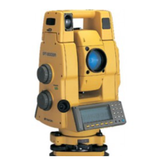
1 NOMENCLATURE AND FUNCTIONS 1 NOMENCLATURE AND FUNCTIONS 1.1 Nomenclature Sighting collimator Handle Handle fixing knob Laser aperture (for optical communication) (GPT-8000A series) Instrument height mark Objective lens Laser aperture (for auto-tracking) (GPT-8000A series) Instrument center mark Tracking indicator (GPT-8000A series) Point guide (GPT-8000 series) Card cover lever... - Page 13 1 NOMENCLATURE AND FUNCTIONS Battery fixing knob Telescope focusing knob Instrument height mark Telescope grip Instrument center mark Vertical shuttle Telescope eyepiece Vertical jog Power switc Horizontal shuttle Plate level Horizontal jog Centronics connector Circular level Tribrach fixing lever Adjusting screws for circular level...
-
Page 14: Display
1 NOMENCLATURE AND FUNCTIONS 1.2 Display • Display In general upper four lines display the measuring data, and the bottom line displays the soft key function which is changed by the measuring mode. • Contrast The contrast and illumination of display window are adjusted by star ( ) key. •... -
Page 15: Operating Key
1 NOMENCLATURE AND FUNCTIONS • The symbol marks for Auto-tracking and Auto-collimating (GPT-8000A series) Auto-collimating Auto-tracking (Laser is emitting) (Laser is emitting) GPT-8000A series is in auto- GPT-8000A series is in auto- collimating status. tracking status. Waiting (Laser is emitting) Searching (Laser is emitting) GPT-8000A series is in waiting GPT-8000A series is searching... -
Page 16: Function Key (Soft Key)
1 NOMENCLATURE AND FUNCTIONS 1.4 Function Key (Soft Key) The Soft Key Functions are labeled on teh bottom of display. Soft Key functions are different for each measurement). 87°55'45"5 HR: 180°44'12"5 0SET HOLD ↓ [F5] [F1] [F2] [F3] [F4] [F6] Soft keys 87°55'45"5 90°10'20"5... - Page 17 1 NOMENCLATURE AND FUNCTIONS Soft Page Display Function Starts slope distance measurement mode. MEAS Changes Continuous/ N-times (single) measurement mode. MODE Changes Fine / Coarse(1mm) /Coarse(10mm) mode. Slope Angle measurement mode. distance Horizontal distance measurement mode. Displays the horizontal distance measuring data after N-times or single measurement.
-
Page 18: Star Key Mode
1 NOMENCLATURE AND FUNCTIONS 1.5 Star Key Mode Press the ( ) key to view the instrument options. Since there are three screens (GPT-8000A series) or two screens (GPT-8000 series) of options, press [F6](1 ) soft key to view the next screen. The following instrument options can be selected from the ( GPT-8000A Series •... - Page 19 1 NOMENCLATURE AND FUNCTIONS GPT-8000A Series • Screen One View Date & Time Electric circular graphic display [F1] The light acceptance quantity level (signal level) is displayed [F2] Set the Temperature, Pressure, Atmospheric Correction Value (PPM), and Prism Constant Value (PSM)[F3] Auto- inversion [F4] Non-prism mode / Prism mode selection [F5] •...
- Page 20 1 NOMENCLATURE AND FUNCTIONS View Date & Time The date and time can be viewed on both screens. To change the displayed order of the date, (Date/Month/Year), (Month / Date / Year) or (Year/Month/Date), see Chapter 8 “PARAMETERS SET- TING MODE” . To set the date and time, see Chapter 9 “CHECK AND ADJUSTMENT”.
- Page 21 1 NOMENCLATURE AND FUNCTIONS Set audio mode The light acceptance quantity level (Signal level) is displayed in this mode. When reflected light from the prism is received, a buzzer sounds. This function is good for easy collimation when the target is difficult to find. Press the [F1] key on screen 3 (GPT-8000A series) or [F2] key on screen 1 (GPT-8000 series).
-
Page 22: Operating Instructions
1 NOMENCLATURE AND FUNCTIONS Point-guide (Point guide type of GPT-8000 series only) This feature is most useful when doing stake out work. The Point Guide's red LEDs on the GPT-8000 Series telescope assist the rod person in getting on-line. The Point Guide feature is fast and simple to use. -
Page 23: Auto Power Off
1 NOMENCLATURE AND FUNCTIONS Laser Plummet (Only for Laser Plummet type) Laser plummet option will help you to center the instrument easily onto the measurement point. Press the star key to view the instrument options. Since there are three screens of options, press [F6](•) soft key twice to view the screen 3. -
Page 24: Rotating Automatically To A Required Horizontal And Vertical Angle
1 NOMENCLATURE AND FUNCTIONS • During auto rotation, don't disturb the instrument.(Stopping the rotation with a touch of the hand). Such action may cause trouble or harm to instrument or operator. See Section 1.5 “Star key mode” for further instructions. 1.8.3 Rotating automatically to a required Horizontal and Vertical angle In Standard Measurement Modes, the instrument can be rotated automatically by input a required horizontal and/or vertical angle. -
Page 25: Using Together With Rc-2Ii Remote Control System (Gpt-8000A Series)
1 NOMENCLATURE AND FUNCTIONS 1.9 Using together with RC-2II Remote Control System (GPT-8000A series) Using together with RC-2II Remote Control System makes it possible to optical communicate between the instrument and remote controller RC-2II, the prism side. This gives easy operation by one man surveying in applying programs. -
Page 26: Using Connecting With Personal Computer (Pc)
1 NOMENCLATURE AND FUNCTIONS 1.10 Using connecting with Personal Computer (PC) Commands for tracking mode correspond only to GPT-8000A series. The auto-tracking function or auto collimating function makes easy remote control of the instrument from PC. The followings are the main communication commands and explanations. How to communi- cate or more informations of communication command, you can see the interface manual which pro- vided optionally.Commands for tracking mode correspond only to GPT-8000A series. -
Page 27: Preparation For Measurement
2 PREPARATION FOR MEASUREMENT 2 PREPARATION FOR MEASUREMENT 2.1 Power Connection (unnecessary if on-board Ni-MH battery BT-56Q is used) See below for connecting the external battery pack. • Battery pack BT-3Q Power cord , PC-5 is used. • Large capacity battery pack BT-3L Power cord PC-6 is used. -
Page 28: Setting Instrument Up For Measurement
Mount the instrument to the tripod. Level and center the instrument precisely to insure the best per- formance. Use tripods with a tripod screw of 5/8 in. diameter and 11 threads per inch, such as the Type E TOPCON wide- frame wooden tripod. Reference: Leveling and Centering the Instrumen Rotate the instrument 90 °... -
Page 29: Power Switch Key On
2 PREPARATION FOR MEASUREMENT 2.3 Power Switch Key ON 1) Confirm the instrument is leveled. Power ON 2) Turn the power switch ON. 3) Type your password. Input a password Self checking mode will display. To skip the self checking, press [F1](ESC) Self check mode key. -
Page 30: Battery Level Indicator
2 PREPARATION FOR MEASUREMENT 2.4 Battery Level Indicator The battery power indicator shows the level of battery strength. Indicates Battery Power Remaining 2002-07-10 15:30:40 Measurement is possible. Prog Std Mem Com Adj Para The power is poor. The battery should be recharged or replace the battery. -
Page 31: Main Menu Icons
2 PREPARATION FOR MEASUREMENT 2.5 Main Menu Icons The main menu icons are as follows. Select the menu by pressing soft keys ([F1]~[F6]). PARAMETERS SETTING MODES The PARAMETERS SETTING MODES are stored in memory once the instrument is OFF. (See Chapter 8 “PARAMETERS SETTING MODE”.) ADJUSTMENT MODES Used for checking and adjustment. -
Page 32: Vertical And Horizontal Angle Tilt Correction
2 PREPARATION FOR MEASUREMENT 2.6 Vertical and Horizontal Angle Tilt Correction When the tilt sensors are activated, automatic correction of vertical and horizontal angle for mislevel- ment is displayed. To ensure a precise angle measurement, tilt sensors must be turned on. The display can also be used to fine level the instrument. -
Page 33: Compensation Of Systematic Error Of Instrument
2 PREPARATION FOR MEASUREMENT • Setting Tilt Correction by Soft Key Enable you to select tilt ON/OFF function on page 2. The setting performed here will be memorized after powering OFF. [Example] Setting X,Y Tilt ON Operating procedure Option Display Press [F6] key to get the function page 2. -
Page 34: Resume Mode On/Off
Alpha and numeric character key entry is simple and quick from the key board. [Example] Renaming a file in the Memory Manager Modes. Operating procedure Option Display Rename Old name [TOPCON .DAT] New name [ ← → Alpha Press [F1](Alpha) key to be entering alphabet [F1] letter mode. -
Page 35: Memory Card
2 PREPARATION FOR MEASUREMENT 2.10 Memory Card How to insert a memory card 1) Pull the card cover lever to open the card cover. 2) Insert a memory card until the card guide is up. 3) Close the card cover. Card cover lever Card guide Memory card... -
Page 36: Inclination Of Prism And Measuring Error (Gpt-8000A Series)
2 PREPARATION FOR MEASUREMENT 2.11 Inclination of Prism and Measuring Error (GPT-8000A series) For the best results, aim or point prisms in the direction of the GPT-8000A series so that maximum signal can be returned to the instrument. Sighting prism obliquely because of inclined settings, may result in measuring errors. - Page 37 2 PREPARATION FOR MEASUREMENT Prism type-2 (Normal prism) Distance Measuring error Angle measuring error Increasing Angle error distance range range ( mm ) ( mm ) C=30 C=30 C=40 C=40 Inclined angle (degree) Inclined angle (degree) Prism type - 3 or 5 (Prism unit A2/A3) Distance Measuring error Angle measuring error Angle error...
-
Page 38: Automatic Tracking
3 AUTOMATIC TRACKING / AUTOMATIC COLLIMATION (GPT-8000A series) 3 AUTOMATIC TRACKING / AUTOMATIC COLLIMATON (GPT-8000A series) WARNING WARNING Cause eye injury or blindness. Do not stare into beam. CAUTION CAUTION Let the laser beam reach the aimed object or the target without anybody else in the laser beam path. In case you operate laser beam open, avoid radiating laser beam to the height of man's head. - Page 39 3 AUTOMATIC TRACKING / AUTOMATIC COLLIMATION (GPT-8000A series) Choose measuring modes by pressing the 90°10'20" [F2] soft keys. HR: 120°30'40" PS M Measuring starts. < Sample: Horizontal distance measuring (m) *c.R MEAS MODE P1↓ If the target prism is lost during auto tracking status, the instrument will automatically change to Waiting status and symbol mark will be switched.
-
Page 40: Automatic Collimation
3 AUTOMATIC TRACKING / AUTOMATIC COLLIMATION (GPT-8000A series) 3.2 Automatic Collimation The function enables to collimate automatically so that the instrument searches for the center of the prism when the telescopic is aimed a prism roughly. Use this mode for the object which is stable. •... -
Page 41: Range Of Laser For Auto-Tracking And Auto-Collimating
3 AUTOMATIC TRACKING / AUTOMATIC COLLIMATION (GPT-8000A series) 3.3 Range of Laser for Auto-tracking and Auto-collimating The range of laser at the long distance is within ±30' as shown in following. So you had better colli- mate the prism so that the prism may be located within this range of laser in the first step. As for it, rapid automatic collimating and automatic tracking becomes possible. -
Page 42: Setting Parameters For Auto-Tracking
3 AUTOMATIC TRACKING / AUTOMATIC COLLIMATION (GPT-8000A series) 3.4 Setting Parameters for Auto-Tracking A proper setting for each parameter are necessary for custom use. The setting of the parameters can be done in the star key mode. 3.4.1 Setting Items Items Selecting item Contents... - Page 43 3 AUTOMATIC TRACKING / AUTOMATIC COLLIMATION (GPT-8000A series) 2) Search Range The search range is the area to searched for the prism by rotating the telescope and body in Searching. The Search range is decided from the point where the prism lost, and the values will be set to plus and minus directions in horizontal and vertical.
-
Page 44: How To Set The Parameters
3 AUTOMATIC TRACKING / AUTOMATIC COLLIMATION (GPT-8000A series) 3.4.2 How to set the parameters Sample setting: Set TRACKING SPEED to [MACHINE CONTROL] Operating procedure Option Display Press the star [ ] key to be in star key 2002-07-07 14:30:40 mode. ↓... -
Page 45: Standard Measurement Mode
4 STANDARD MEASUREMENT MODE 4 STANDARD MEASUREMENT MODE 4.1 Angle Measurement 4.1.1 Measuring Horizontal Angle Right and Vertical Angle Make sure the mode is in Angle measurement. Operating procedure Operation Display Collimate the 1st target (A). 87°55'45" Collimate HR: 180°44'12" ↓... -
Page 46: Switching Horizontal Angle Right/Left
4 STANDARD MEASUREMENT MODE 4.1.2 Switching Horizontal Angle Right/Left Make sure the mode is Angle measurement. Operating procedure Operation Display ↓ Press [F6]( )key to get the function as on 87°55'45" page 2. HR: 120°30'40" ↓ 0SET HOLD P1 [F6] ↓... -
Page 47: Vertical Angle Percent Grade(%) Mode
4 STANDARD MEASUREMENT MODE 2) Setting a Horizontal Angle from the Keys Make sure the mode is Angle measurement. Operating procedure Operation Display Collimate the target. Collimate 90°10'20" HR: 120°30'40" ↓ 0SET HOLD ↓ Press [F6]( ) key to get the function as on [F6] ↓... -
Page 48: Automatic Rotation To A Required Horizontal And Vertical Absolute Angle
4 STANDARD MEASUREMENT MODE 4.1.5 Automatic Rotation to a Required Horizontal and Vertical Absolute Angle The GPT-8000A/8000 series can be rotated to a required horizontal and vertical absolute angle by direct key input. Example: Both vertical and horizontal angle Operating procedure Operation Display ↓... -
Page 49: Distance Measurement
PHERIC CORRECTION” . 4.2.2 Setting of the Correction for Prism Constant / Non-prism Constant Topcon's prism constant value is 0. Set correction for prism at 0. If the prism is of another manufac- ture, the appropriate constant shall be set beforehand. -
Page 50: Distance Measurement (Continuous Measurement)
4 STANDARD MEASUREMENT MODE 4.2.3 Distance Measurement (Continuous Measurement) Make sure the mode displays angle measurement. Operating procedure Operation Display Collimate the center of prism. 90°10'20" HR: 120°30'40" ↓ 0SET HOLD 90°10'20" Press [F1](SD) key or [F2]( HD )key. [F2] HR: 120°30'40"... -
Page 51: Distance Measurement (Single/N-Times Measurement)
4 STANDARD MEASUREMENT MODE 4.2.4 Distance Measurement (Single/N-times Measurement) When presetting the number of times, the instrument measures the distance as the setting times and the average distance will be displayed. When presetting the number of times as 1, it does not display the average distance, because of single measurement. - Page 52 4 STANDARD MEASUREMENT MODE 90°10'20" HR: 120°30'40" 54.321 1.234 (m) *F.N ↓ MEAS MODE NEZ P1 The average value is displayed following with buzzer sound and “ * ” mark disappears. 90°10'20" HR: 120°30'40" 54.321 1.234 ↓ MEAS MODE NEZ P1 Press [F1](MEAS) key for re-measuring after the measurement in held.
-
Page 53: Fine / Coarse Measuring Mode
4 STANDARD MEASUREMENT MODE 4.2.5 Fine / Coarse Measuring Mode •Fine mode : This is a normal distance measuring mode. Measurement time 0.2mm mode: approx.3 seconds 1 mm mode : approx.1.2 seconds The unit to be displayed is 0.2mm or 1mm. (0.001ft or 0.005ft) •Coarse mode : This mode measures in shorter time than in fine mode. -
Page 54: Stake Out (S-O)
4 STANDARD MEASUREMENT MODE 4.2.6 Stake Out (S-O) The stake out distance is the difference between the measured distance and the preset distance. Display value = Measured distance -Standard (Preset) distance The value on the display is the distance in which the rod person must move toward or away from the instrument. -
Page 55: Setting Coordinate Values Of Occupied Point
4 STANDARD MEASUREMENT MODE 4.3.1 Setting Coordinate Values of Occupied Point The occupied point coordinates (NEZ) can be preset in the GPT-8000A/8000 Series to calculate the unknown point coordinates. It is possible to retain the occupied coordinates in memory once the power is turned OFF if the (NEZ mem) is ON in the Parameter Setting Modes. - Page 56 4 STANDARD MEASUREMENT MODE Input new data and press [ENT] key. *1) N coord. Setting occ. point [ENT] N : 0.0000 E coord. E : 0.0000 [ENT] Z : 0.0000 Z coord. EXIT [ENT] Complete < Measuring starts. (m) *F.R ↓...
-
Page 57: Coordinate Measurement
4 STANDARD MEASUREMENT MODE 4.3.2 Setting of the Instrument Height / Prism Height The instrument height and prism height are used to compute the ground elevation of the unknown point. If the option to store NEZ is (on), the instrument and prism heights will be stored in memory when power is turned off. -
Page 58: Execution Of Coordinate Measuring
4 STANDARD MEASUREMENT MODE 4.3.3 Execution of Coordinate Measuring Measure the coordinates by entering the instrument height and prism height, coordinates of unknown point will be measured directly. • When setting coordinate values of occupied point, see Section 4.3.1“Setting Coordinate Values of Occupied Point”... - Page 59 4 STANDARD MEASUREMENT MODE The result will be shown. 12345.6789 E : -12345.6789 10.1234 (m) *F.R ↓ MEAS MODE VH HD P1 *1) In case the coordinate of instrument point is not entered, (0,0,0) will be used as the default for the instrument point.
-
Page 60: Data Output
4 STANDARD MEASUREMENT MODE 4.4 DATA OUTPUT Result of measurement is transferred to Data Collector (FC series) from GPT-8000A/8000 series. [Example: Distance measurement mode] Confirm the distance measurement mode. Operating procedure Display Operate the data collector to measure the distance. 90°10'20"... - Page 61 Under tilt compensation Tilt Over Tilt OFF • Control by interface for Topcon AP-L1A system, see Chapter 5 “PROGRAM MODES” -[EXT.LINK] section • When using other wireless modem or optical remote controller, select to [None] for the protocol of communication in Chapter 8 “PARAMETERS SETTING MODE”.
-
Page 62: Program Modes
5 PROGRAM MODES 5 PROGRAM MODES 2002-07-10 15:30:40 [Press [F1] key.] Prog Std Mem Com Adj Para PROGRAM MODE (APPLICATION MEASUREMENT) 1.Setting a Horizontal Angle 2.Retaining a Coordinate (STORE-NEZ) 3.Remote Elevation Measurement (REM) 4.Missing Line Measurement (MLM) 5.Line Measurement (LINE) 6.Offset Measurements (OFF SET) 7.External Link (only for GPT-8000A series) Programs... -
Page 63: Setting A Direction Angle For Backsight Orientation
5 PROGRAM MODES 5.1 Setting a Direction Angle for Backsight Orientation (Entering the instrument and backsight coordinate values) From the coordinate value of backsight point (bearing point) and instrument point, the direction angle from the instrument point to the backsight point can be set. Backsight point A Instrument point C Direction angle... -
Page 64: Retaining A Coordinate (Store- Nez)
5 PROGRAM MODES 5.2 Retaining a Coordinate (STORE- NEZ) Suppose the instrument P0 moves to P1, P2, P3, etc. and the coordinate at P1, P2, P3 etc., last point will be retained in the memory, after moving, as from the origin point. Known point A Direction angle Inst. - Page 65 5 PROGRAM MODES Press [F6](SET) key. [F6] Store NEZ Coordinate of P1 will be displayed. 123.456 m 12.345 m 1.234 m > SET OK? Press [F5](YES) key. [F5] Coordinate of P1 will be decided. Complete The display return to main menu. Power off Move to Turn power off and move instrument to P1...
-
Page 66: Remote Elevation Measurement (Rem)
5 PROGRAM MODES 5.3 Remote Elevation measurement (REM) To obtain elevation of the point at which setting the target prism is not possible, place the prism at any point on the vertical line from the target then carry out REM procedure as follows. T a rget K Prism P Prism height... - Page 67 5 PROGRAM MODES Horizontal distance (HD) between the instrument and prism will be shown. (2)Horizontal Distance HD : 123.456 m MEAS Press [F6](SET) key. [F6] The prism position will be decided. *1) VD : 0.234 m EXIT P.h HD Collimate target K. Collimate Vertical distance (VD) will be shown.
- Page 68 5 PROGRAM MODES Press [F6](SET) key. [F6] The prism position will be decided. (2)Vertical Angle 120°30'40" Collimate ground point G. Collimate (2)Vertical Angle 95°30'40" Press [F6](SET) key. [F6] The position of point G will be decided. *1) VD : 0.000 m EXIT Collimate target K.
-
Page 69: Missing Line Measurement (Mlm)
5 PROGRAM MODES 5.4 Missing Line Measurement (MLM) Measurement for horizontal distance (dHD), slope distance (dSD) and elevation (dVD) between two target prisms. MLM mode has two mods. 1.(A-B, A-C):Measurement is A-B, A-C, A-D,..... 2.(A-B, B-C):Measurement is A-B, B-C, C-D,..... Prism A Prism B Instrument... - Page 70 5 PROGRAM MODES Collimate prism A, and press [F1](MEAS) key. Collimate MLM 1 Horizontal distance (HD) between the [F1] Horizontal Distance 1 instrument and prism A will be shown. HD * < m MEAS MLM 1 Horizontal Distance 1 HD : 123.456 m MEAS Press [F6](SET) key.
- Page 71 5 PROGRAM MODES MLM 1 Horizontal Distance 2 HD * 246.912 m MEAS Press [F6]( SET) key. MLM 1 [F6] The horizontal distance (dHD) relative dHD : 123.456 m elevation (dVD) and slope distance between dVD : 12.345 m prism A and C. dSD : 12.456 m EXIT HD...
-
Page 72: Line Measurement (Line)
5 PROGRAM MODES 5.5 Line Measurement (LINE) This mode is useful to obtain the line height. Prism B P . h Prism A Instrument [Example:Input of prism height] Operating procedure Operation Display Programs F1 BS F2 STORE F3 REM F4 MLM MORE Press [F6](MORE) key from programs menu [F6]... - Page 73 5 PROGRAM MODES Collimate prism A and press [F1](MEAS) key. Collimate LINE The distance measurement will start. <STEP-1>P [F1] < m Horizontal distance is displayed. LINE <STEP-1>PT A 50.234 m MEAS Press [F6] (SET) key, and horizontal distance [F6] LINE will be recorded.
- Page 74 5 PROGRAM MODES Rotate the vertical tangent screw, and sight Sight G LINE ground point G. G-POINT 90°40'20" EXIT Press [F6] (SET) key, line height (LH) and [F6] LINE horizontal distance (Off) are displayed. 33.765 m Off: 27.521 m EXIT NEXT To finish the measurement, press the [F1](EXIT) or [ESC] key.
-
Page 75: Offset Measurement (Offset)
5 PROGRAM MODES 5.6 Offset measurement (OFFSET) There are four offset measurement modes in the Offset Measurement. • Angle offset • Distance offset • Plane offset • Column offset Offset Measurement Menu Programs F1 LINE F2 OFFSET F3 EXT.LINK MORE [F2](OFFSET) OFFSET MEASUREMENT 1.ANGLE OFFSET... -
Page 76: Angle Offset
5 PROGRAM MODES 5.6.1 Angle Offset This mode is useful when it is difficult to set up the prism directly, for example at the center of a tree. Place the prism at the same horizontal distance from the instrument as that of point A0 to measure. To measure the coordinates of the center position, operate the offset measurement after setting the instrument height/prism height. - Page 77 5 PROGRAM MODES Select the vertical angle [FREE] or [HOLD]. [F1]or [F2] ANGLE OFFSET MEAS Collimate prism P, and press the [F1](MEAS) Collimate ANGLE OFFSET key. *1) [F1] < m MEAS The horizontal distance from the instrument to the prism will be measured. ANGLE OFFSET 20°3 0'40"...
-
Page 78: Distance Offset Measurement
5 PROGRAM MODES 5.6.2 Distance Offset Measurement The measurement of a place apart from a prism is possible by inputting offset horizontal distance of front and back / right and left. Forward HD oHD sign RorL HD Prism height Prism P Instrument height Occ.Point When measuring coordinates of ground point A... - Page 79 5 PROGRAM MODES If you reset the offset value, press the [F6] DIST. OFFSET [F6](INP) key and input the value. *1) dFR : 0.000 dRL : 0.000 EXIT Collimate prism using the horizontal motion Collimate DIST. OFFSET clamp and horizontal tangent screw. Press the [F1](MEAS) key.
-
Page 80: Plane Offset Measurement
5 PROGRAM MODES 5.6.3 Plane Offset Measurement Measuring will be taken for the place where direct measuring can not be done, for example distance or coordinate measuring for a edge of a plane. Three random target points (P1, P2, P3) on a plane will be measured at first in the plane offset meas- urement to determine the measured plane. - Page 81 5 PROGRAM MODES Collimate prism P1, and press the Collimate PLANE OFFSET [F1](MEAS) key. N002# Measuring will start. [F1] SD : After measuring, the second point measurement screen will be shown. MEAS Measure the second and third prism in the Collimate PLANE OFFSET same way.
-
Page 82: Column Offset Measurement
5 PROGRAM MODES 5.6.4 Column Offset Measurement If it is possible to measure circumscription point (P1) of column directly, the distance to the center of the column (P0), coordinate and direction angle can be calculated by measured circumscription points (P2)and (P3). Prism Operating procedure Operation... - Page 83 5 PROGRAM MODES Collimate the left side of the column (P2) and Collimate COLUMN OFFSET press the [F6](SET) key. Right [F6] 95 °3 0'40" HR : After the measurement, angle measuring display of the right side (P3) will be shown. Collimate the right side of the column (P3) Collimate COLUMN OFFSET...
-
Page 84: External Link (Gpt-8000A Series)
(1)Setting communication course Select a communication course according to the using optional device. 1) Cable : In case connecting personal computer or other than Topcon's designated wireless modem to the RS-232C connector. 2) RADIO MODEM : In case connecting Topcon's designated wireless modem. - Page 85 In case connecting Topcon's designated wireless modem, simply select communication course as "RADIO MODEM" it is enough to do setting of parameter automatically. In case connecting personal computer or other than Topcon's designated wireless modem, it is required to do parameters setting for RS-232C before using.
- Page 86 5 PROGRAM MODES Press the [F2] key to select [2PARAMETER [F2] SPEED (CABLE)]. Speed setting screen will appear. 9600 ↑ ↓ EXIT Press the [F3](↑) or [F4](↓) key to select baud [F3] BIT FORMAT rate then press the [F1](SET) key to decide. [F4] NONE [F1]...
- Page 87 5 PROGRAM MODES 4) REC TYPE Select the option to record the data for the distance measurement. REC-A : Measure the distance again and record the updated distance. REC-B : Record the data for the last distance measurement on the display. Operating procedure Operation Display...
-
Page 88: Carrying Out Communication
5 PROGRAM MODES 2) REC TYPE Select the option to record the data for the distance measurement. REC-A : Measure the distance again and record the updated distance. REC-B : Record the data for the last distance measurement on the display. Operating procedure Operation Display... - Page 89 5 PROGRAM MODES 5-28...
-
Page 90: Memory Manage Modes
Init. File Example: Internal Memory Press [F6](File) key. [F6] .DAT 1597 12-25 Each File status (File name, File name TOPCON .DAT 1089 10-05 extension, Used memory capacity, Date) are .TXT 2450 09-11 shown. HILL .DAT 31777... -
Page 91: Protect A File
Select a file using [F5]( ↑ ) key or [F6]( ↓ ) key. Select a file Press [F2](Ren) key. [F2] Rename Old name [TOPCON .DAT] New name [ ← ← → Alpha Enter a new file name within 8 characters. -
Page 92: Deleting A File
File protection must be removed before you can delete a file. Only one file can be erased at a time. Operating procedure Operation Display Proceed Chapter 6.1. .DAT 1597 12-25 TOPCON .DAT 1089 10-05 .TXT 2450 09-11 HILL .DAT 31777 08-19 ↑... -
Page 93: Initializing Memory
Example: Initializing card memory Operating procedure Operation Display MEMORY manage F1 Internal memory F2 Card memory Press [F2] key to select card memory. [F2] Card name [TOPCON Memory size 1967KByte Memory free 1951KByte Card battery expire 11/99 Init File Press [F1](Init) key. -
Page 94: Communication Modes
Init. File Example: Internal Memory Press [F6](File) key. [F6] .DAT 1597 12-25 Each File status (File name, File name TOPCON .DAT 1089 10-05 extension, Used memory capacity, Date) are .TXT 2450 09-11 shown. HILL .DAT 31777... -
Page 95: Data File In
Data file out F1 Internal memory F2 Card memory Press [F1](Internal memory) or [F2](Card [F1] to[F2] .DAT 1597 12-25 memory) key and press [ENT] key. [ENT] TOPCON .DAT 1089 10-05 Example: Internal memory .TXT 2450 09-11 HILL .DAT 31777 08-19 ↑... -
Page 96: Parameters Setting Mode
/ gon / mil measuring angle unit to be shown on the displ a y. Select the minimum display angle reading ON or OFF. GPT-8001A/8001 [ OFF:1" / ON:0.5" ] GPT-8002A/8002 [ OFF:1" / ON:0.5" ] 2.Min.Angle OFF / ON GPT-8003A/8003 [ OFF:5"... -
Page 97: Parameters For Communication
8 PARAMETERS SETTING MODE Select the distance measuring unit Meter or Feet shown on 9.Dist. Unit METER /FEET the display. Select the meter / feet conversion factor. US SURVEY feet 10.C.F. m/ft Us.f /Intl.f 1m =3.280833333333333 ft. INTERNATIONAL feet 1m =3.280839895013123 ft. Select OFF or ON for the minimum distance in fine mode. - Page 98 8 PARAMETERS SETTING MODE 4.Stop Bit 1 / 2 Select the stop bit. Select the option OFF or ON for carriage return and line feed 5.Delimit ETX / CRLF when collecting measurement data with a computer. Select the option to record the data. 6.REC-A/B A / B REC-A : The measurement is started and new data is output.
-
Page 99: Setting Parameters
8 PARAMETERS SETTING MODE Setting parameter for RC Menu Selecting Item Contents 1.Channel 1 / 2 / 3 Sets communication channel when using RC-2H. Selecting the vertical range for searching a prism when using with RC-2H. 2.V.Search 15 / 30 –15 °... - Page 100 8 PARAMETERS SETTING MODE Select the menu by pressing [F6]( ↓ ) key. [F6] Parameters (Measurement) (Example: S/A buzz.)) S/A buzz. W-corr. [ 0.14 ] 0.20 N/E/Z mem ↑ ↓ EXIT <- -> Press [F3](←) key, and select OFF. [F3] Parameters (Measurement) S/A buzz.[ OFF W-corr.
-
Page 101: Password Option
8 PARAMETERS SETTING MODE Press the [F2](Set RS232C) key. [F2] Parameters (Communication) The next steps are same as Section 8.2.1- B.Rate [1200] 2400 4800 9600 Parameters Setting for communication, refer Data.L to the section 8.2.1. Parity none [even] ↑ ↓ I.GTS <- ->... - Page 102 8 PARAMETERS SETTING MODE The confirmation screen will appear to Type Password confirm your password. password [ON] Type the password in once again and press [ENT] [ENT]. EXIT CHANGE The password option screen will appear once again for 2 seconds and will automatically change to the main menu icons.
- Page 103 8 PARAMETERS SETTING MODE Changing a Password Once a password is established, you can change the original password. The new password takes the place of the original password in memory. Changing the Password Operating procedure Operation Display From the main menu icons, press [F6](Para) [F6] Parameters to access the parameters option menu.
-
Page 104: Check And Adjustment
If using above procedure and no difference is found from the instrument constant at the factory or a difference of over 5mm is found, contact TOPCON or your TOPCON dealer. 9.1.1 Checking of the accuracy of the non-prism mode If you reset the instrument constant, you must check the accuracy of the non-prism mode. -
Page 105: Checking The Optical Axis
9 CHECK AND ADJUSTMENT 9.2 Checking the Optical Axis To check if the optical axis of EDM and theodolite are matched, follow the procedure below. It is especially important to check after adjustment of the eyepiece reticle is carried out. Position a prism about more than 150 m apart from GPT-8000A/8000 series. - Page 106 Carry out as Horizontal direction confirmation. Compare the reading Vertical angle value and calculated value. If the difference is within 1’ 30”, no problem for use. If the difference is more than mentioned value, contact with your Topcon dealer or Topcon. [Example] 90¡12 30 90¡...
-
Page 107: Checking/Adjusting The Theodolite Functions
9 CHECK AND ADJUSTMENT 9.3 Checking/Adjusting the Theodolite Functions • Pointers on the Adjustment Adjust the eyepiece of the telescope properly prior to any checking operation which involves sighting through the telescope. Remember to focus properly, with parallax completely eliminated. Carry out the adjustments in the order of item numbers, as the adjustments are dependent one upon another. -
Page 108: Checking /Adjusting The Plate Level
9 CHECK AND ADJUSTMENT 9.3.1 Checking /Adjusting the Plate Level Adjustment is required if the axis of the plate level is not perpendicular to the vertical axis. • Check Place the plate level parallel to a line running through the centers of two leveling screws, say, A and B. -
Page 109: Adjustment Of The Vertical Cross-Hair
9 CHECK AND ADJUSTMENT 9.3.3 Adjustment of the Vertical Cross-hair Adjustment is required if the vertical cross-hair is not in a place perpendicular to the horizontal axis of the telescope (since it must be possible to use any point on the hair for measuring horizontal angles or vertically running lines). -
Page 110: Collimation Of The Instrument
9 CHECK AND ADJUSTMENT 9.3.4 Collimation of the Instrument Collimation is required to make the line of sight of the telescope perpendicular to the horizontal axis of the instrument, otherwise, it will not be possible to extend a straight line by direct means. Eyepiece •... -
Page 111: Checking / Adjusting The Optical Plummet Telescope
9 CHECK AND ADJUSTMENT Note: First, loosen the capstan adjustment screw on the side to which the vertical cross-hair line must be moved. Then tighten the adjustment screw on the opposite side by an equal amount which will leave the tension of the adjustment screws unchanged. Revolve in the counterclockwise direction to loosen and in the clockwise direction to tighten, but revolve as little as possible. -
Page 112: Checking / Adjusting The Laser Plummet (For Laser Plummet Type)
9 CHECK AND ADJUSTMENT 9.3.6 Checking / Adjusting the Laser Plummet (For Laser Plummet type) • Check Turn on the laser plummet and coincide the center of the laser with a measuring point. Rotate the instrument 180° or 200g around the vertical axis and check the measuring point. If the laser is properly centered in the measuring point, adjustment is not required. -
Page 113: Adjustment Of Compensation Systematic Error Of Instrument
9 CHECK AND ADJUSTMENT 9.4 Adjustment of Compensation Systematic Error of Instrument Error of vertical axis (X,Y tilt sensor offset) Collimation error Error of vertical angle 0 datum Error of horizontal axis The above mentioned errors will be compensated by software, which calculated internally according to each compensation value. - Page 114 9 CHECK AND ADJUSTMENT Collimate target A. Collimate (Reverse) Press [F6](SET)key. [F6] FACE 2 Repeat the procedures in step LEVEL±0 that the count of measured times matches to V:270° 04'20" the one in FACE(1). * 2),3),4) SKIP The title display will be shown automatically. (B)HORIZONTAL Axis FACE 2 LEVEL±10°...
-
Page 115: Showing Constant List And Switch On/Off Compensation Systematic Error Of Instrument
9 CHECK AND ADJUSTMENT 9.5 Showing Constant List and Switch ON/OFF Compensation Systematic Error of Instrument [Example setting: Switch OFF the compensation] Operating procedure Operation Display Press [F5] key from the main menu. [F5] Adjustment F1 V0/Axis (Measurement) F2 V0/Axis (Constant list) F3 Date Time ↓... -
Page 116: How To Adjust The Date And Time
9 CHECK AND ADJUSTMENT 9.6 How to adjust the date and time Operating procedure Operation Display Press [F5] key from the main menu. [F5] Adjustment F1 V0/Axis (Measurement) F2 V0/Axis (Constant list) F3 Date Time ↓ F4 Instrument constant Press [F3] key. [F3] Current date will be on the display. -
Page 117: How To Set The Instrument Constant Value
9 CHECK AND ADJUSTMENT 9.7 How to Set the Instrument Constant Value To set the Instrument constant which is obtained in section 9.1 “Checking and Adjusting of Instrument Constant”, follow as below. Note: Each of the Prism mode and Non-prism mode has instrument constant. You must obtain the instrument constant of prism mode. -
Page 118: Inspection And Adjustment Of Optic Axis For Auto -Tracking (Gpt-8000A Series)
9 CHECK AND ADJUSTMENT 9.8 Inspection and Adjustment of Optic Axis for Auto -Tracking (GPT-8000A Series) Activates auto tracking to the prism. Confirm if the center of telescope reticle and the center of the prism is coincided. Any error between them requires adjustment according to the following procedure. Prism center Prism center Telescope reticle center... - Page 119 9 CHECK AND ADJUSTMENT Press the [F6](MEAS) key. [F6] Adj Tracking Axis The measurement starts. Wait The shifted quantity between H angle and V Adj Tracking Axis angle measured from the measuring will be calculated internally. >Set OK? Press the [F5](YES) key. [F5] The compensation value will be set and memorized to GPT-8000A series.
-
Page 120: Setting The Prism / Non-Prism Constant Value
10 SETTING THE PRISM / NON-PRISM CONSTANT VALUE The prism constant value of Topcon is set to zero. When using prism other than Topcon's, it is neces- sary to set the prism constant correction value of that specific prism. Once you set the correction value for prism constant, it is retained after power is OFF. -
Page 121: Setting Atmospheric Correction
11 SETTING ATMOSPHERIC CORRECTION 11 SETTING ATMOSPHERIC CORRECTION The velocity of light through air is not constant and depends on the atmospheric temperature and pressure. The atmospheric correction system of this instrument corrects automatically when the correction value is set. 15•••C/59•••F, and 1013.25hPa / 760mmHg / 29.9 inHg is as a standard value for 0ppm in this instrument. - Page 122 11 SETTING ATMOSPHERIC CORRECTION Input Pressure value, and press [ENT]. Enter 26.0 °C [Example] Pres. :1020.0hPa. +14.0 mm value 1020.0hPa The display returns previous mode. 23.6 mm *1) *2) 5.1ppm [ENT] The display returns STAR key menu. -30.0 °C to +60.0 °C (0.1 °C step) *1) Range : Temp.
- Page 123 11 SETTING ATMOSPHERIC CORRECTION Atmospheric Correction Chart (For your reference) The atmospheric correction value is obtained easily with the atmospheric correction chart. Find the measured temperature in horizontal, and pressure in vertical on the chart. Read the value from the diagonal line, which represents the required atmospheric correction value. Example: The measured temperature is +26°C The measured pressure is 1013 hPa...
- Page 124 11 SETTING ATMOSPHERIC CORRECTION 11-4...
- Page 125 11 SETTING ATMOSPHERIC CORRECTION 11-5...
-
Page 126: Correction For Refraction And Earth Curvature
12 CORRECTION FOR REFRACTION AND EARTH CURVATURE 12 CORRECTION FOR REFRACTION AND EARTH CURVATURE The instrument measures distance, taking into account correction for refraction and earth curvature. Note: If the telescope is positioned within ±9° from the nadir or zenith, no measurement will result even if the correction function for refraction and earth curvature works. -
Page 127: Power Source And Charging
13 POWER SOURCE AND CHARGING 13 POWER SOURCE AND CHARGING 13.1 Rechargeable Battery BT-56Q • To remove Remove the battery while pulling both battery fixing levers. BC-27BR/CR BT-56Q AC-outlet Battery fixing lever •To charge Plug the charger into the outlet. Connect the charger connector to the battery, then charging will start. - Page 128 13 POWER SOURCE AND CHARGING • Do not charge or discharge continuously, otherwise the battery and the charger may be deteriorated. If charging or discharging is necessary, use the charger after stopping charge for approximately 30 minutes. • Do not charge the battery or discharge the battery in right after the battery is charged, it causes deterioration of the battery in rare cases.
-
Page 129: Detach/Attach Of Tribrach
14 DETACH/ATTACH OF TRIBRACH 14 DETACH/ATTACH OF TRIBRACH The instrument is easily detached or attached to the tribrach. Alignment piece Tribrach alignment groove • Detachment Loosen the tribrach fixing screw. Loosen the tribrach fixing lever by turning counterclockwise. Lift the instrument straight upwards and off. •... -
Page 130: Battery System
15 BATTERY SYSTEM 15 BATTERY SYSTEM In case of Rechargeable Battery BT-56Q In case of External battery Pack BT-3Q BT-3L PC-5 PC-6 AC-6 BT-56Q PC-5 or PC-6 GPT-8000A/8000 series GPT-8000A/8000 series External 12V battery Charging Charging time BC-27BR/CR Quick BC-27BR for AC 120V use Approx. -
Page 131: Prism System
16 PRISM SYSTEM 16 PRISM SYSTEMS Arrangement according to your needs is possible. Use the above prisms after setting them at the same height as the instruments. To adjust the height of prism set, change the position of fixing screws. Plug 3 is necessary for the tribrach adaptor-2, tribrach adaptor-S2 and pole adaptor-F2 to coincide with the height of GPT-8000A/GPT-8000 series. -
Page 132: Precautions
Even if any abnormality occurs, never attempt to disassemble or lubricate the instrument yourself. Always consult with TOPCON or your dealer. To remove the dust on the case, never use thinner or benzine. Use a clean cloth moistened with neutral detergent. -
Page 133: Error Displays
Abnormality in angle measuring system. required. E800‘s In the self checking mode, vibration is too big. Get rid of the Vibration • If error still persist after attempting to clear them, contact your local Topcon dealer or Topcon head office. 18-1... -
Page 134: Special Accessories
19 SPECIAL ACCESSORIES 19 SPECIAL ACCESSORIES Remote Control System RC-2II Using together with RC-2II makes it possible to optical communication between the GPT-8000A series and RC-2II. This gives easy operation for one man surveying. Tribrach TR- 5 Optical plummet tribrach TR-5P This is detachable tribrach having tribrach fixing This is detachable tribrach having built-in optical screw. - Page 135 19 SPECIAL ACCESSORIES Prism unit case, Model 6 Prism unit case, Model 3 Fixed 9 prisms unit or tilting 3 prisms unit can be This is the plastic case to store and carry various stored in this case. Especially, this is a very easy sets of prisms.
- Page 136 19 SPECIAL ACCESSORIES Power cord PC-6 (For BT-3L) Power cord PC-5 • L-shape plug provided (For BT-3Q and TOPCON FC series Data collector) • Cord length: 2m approx. • L-shape plug provided • Cord length: 2m approx. Large capacity battery pack BT-3L Auto Converter AC-6 •...
-
Page 137: Specifications
Image: Erect Field of view: 1°30' Resolving power: 3" Minimum focus: 1.3m Focusing knob GPT-8001A/8002A/8001/8002: 2 speed way GPT-8003A/8003/8005A/8005: 1 speed way Automatic Tracking / Collimating (GPT-8000A series) Maximum Automatic Tracking speed: 12° /sec Automatic Collimating area: ±5° Automatic Tracking range *1:... - Page 138 20 SPECIFICATIONS Distance measurement Measurement range Non-prism mode (Target: White wall) Atmospheric conditions In low light condition and without sun glare on target 3 to 120 m (9.8 to 394 ft) Prism mode Atmospheric conditions Prism Condition 1 Mini prism 2 to1,500m (6.6 to 4,920ft) Prism type 2, with 1 prism 2 to 7,000m (6.6 to 22,900ft)
- Page 139 Electronic Angle Measurement Method: Absolute reading Detecting system: Horizontal : 2 sides Vertical: 2 sides Minimum reading GPT-8001A/8001: 1"/0.5" (0.5mgon/0.1mgon, 5mmil/2mmil) reading GPT-8002A/8002*: 1"/0.5" (0.5mgon/0.1mgon, 5mmil/2mmil) reading GPT-8003A/8003: 5"/1" (1mgon/0.2mgon, 20mmil/5mmil) reading GPT-8005A/8005: 5"/1" (1mgon/0.2mgon, 20mmil/5mmil) reading *Minimum reading of GPT-8002A/8002 will be differed by the market.
- Page 140 20 SPECIFICATIONS Computer unit MS-DOS Ver.3.22 Internal Memory System memory: FEEPROM 512KB Main memory: RAM 640 KB Data memory: FEEPROM 2 MB Program memory: FEEPROM 1 MB Application program memory: FEEPROM 2 MB PC Card Slot: Based on PC Card Standard 95 (Memory card or ATA card, Type l/ll) Max.
-
Page 141: Appendix
APPENDIX APPENDIX 1 Dual Axis Compensation Inclination of the vertical axis with respect to true vertical will result in incorrectly measured horizontal angles. The extent of the error in horizontal angle measurement due to axis tilt depends on three factors : •... - Page 142 APPENDIX It is clear from the table that dual axis compensation has the most benefit when the elevation of the target is greater then 30° and the axis is tilted more than 10". The entries indicated in bold in the table show, in fact, that for many common surveying applications i.e.
-
Page 143: Precaution When Charging Or Storing Batteries
APPENDIX 2 Precaution when Charging or Storing Batteries The capacity of battery will be affected and its service life shortened in any of the following cases while it is recharged, discharged or stored. Recharging Fig. 1 shows how ambient temperature at recharging is related to charging efficiency or as affect- ing discharge capacity. - Page 144 APPENDIX 0.1C charge Discharge : 0.2, E.V. Temperature at discharge : 20 Ambient temperature when charging i Fig.1 Recharging 0.2C discharge 1C discharge Charging : 0.1C ~16hours Charging temperature : 20 Ambient temperature i Fig. 2 Discharge Charging : 0.1C ~16hours Discharge : 0.2 C, E.V.=1.0V Storing period (month) Fig.
-
Page 145: License Agreement
LICENSE AGREEMENT END USER LICENSE AGREEMENT IMPORTANT-- READ CAREFULLY BEFORE USING THE EMBEDDED SYSTEM WHICH CONTAINS MI-CROSOFT SOFTWARE. By using the embedded system containing software, you indicate your acceptance of the following Software License Agreement. SOFTWARE LICENSE AGREEMENT (Embedded Products) This software license agreement, including the Warranty and Special Provisions set forth in the appendix or separate booklet included in this package, is a legal agreement between you (either an individual or an entity, herein-after "End User") and the manufacturer ("Embedded System Manufacturer") of the embedded system containing software prod-...
Need help?
Do you have a question about the GPT-8001A and is the answer not in the manual?
Questions and answers