Sign In
Upload
Manuals
Brands
Topcon Manuals
Measuring Instruments
IS205
Topcon IS205 Imaging Total Station Manuals
Manuals and User Guides for Topcon IS205 Imaging Total Station. We have
1
Topcon IS205 Imaging Total Station manual available for free PDF download: Instruction Manual
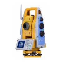
Topcon IS205 Instruction Manual (170 pages)
Imaging station
Brand:
Topcon
| Category:
Measuring Instruments
| Size: 10 MB
Table of Contents
Foreword
3
General Handling Precautions
4
Display for Safe Use
5
Safety Cautions
5
User
8
Exceptions from Responsibility
8
Laser Safety
9
Labels
9
Symbol Mark While the Laser Is Emitting
10
Table of Contents
11
Contents
11
1 Nomenclature and Functions
14
Nomenclature
14
Display
16
Main Menu Contains
16
Measurement Menu
17
Display Marks
17
Display Keys
18
Shortcut Keys
18
Backlight, Key Light Adjustment
19
How to Adjust Reducing Time of Backlight
19
Adjust the Backlight Brightness by Manual
21
Selecting the Automatic Lighting Option
22
Selecting the Key Light Option
23
RAM Data Backup
24
Execute the Backup Function
24
Set the Automatic Backup for Every Suspension
26
Set the Restoration after Hardware Reset
26
Hardware Reset
27
Cover Sensor
27
Touch Panel Calibration
28
Operating Panel Key
30
Operating Key
30
Turning off the Touch Panel Function
31
Power off
31
Operation Key(Touch Panel)
32
Star Key Mode
34
Switching Measurement Distance Modes
38
Setting by Using Star Key
39
Auto Power off
40
Focus Function
42
Manual Focus
42
Assist Focus
42
Setting Focus Function
43
Rotating Method
44
Rotating by H/V Shuttle and H/V Jog
44
Auto Inversion
44
Rotating Automatically to a Required Horizontal and Vertical Angle
44
Using Together with RC-3 Remote Control System
45
Using Connecting with Personal Computer (PC)
46
Using the USB Port
47
2 Preparation for Measurement
48
Power Connection
48
Setting Instrument up for Measurement
49
Power Switch Key on
50
Battery Power Remaining Display
51
Vertical and Horizontal Angle Tilt Correction
52
Setting Tilt Correction by Operation Key
53
Correction of a Tilt Sensor Setting Error
53
Compensation of Systematic Error of Instrument
54
How to Enter Numerals and Alphabet Letters
55
Data Memory Card
59
Active Sync
60
Getting Connected
60
Confirming the Bluetooth® Device Address and Setting the PIN Code
60
Wireless LAN Function ON/OFF
61
Inclination of Prism and Measuring Error
61
3 Automatic Tracking / Automatic Collimation
63
Automatic Tracking
64
Automatic Collimation
66
Range of Laser for Auto-Tracking and Auto-Collimating
67
Setting Parameters for Auto-Tracking
68
Setting Items
68
How to Set the Parameters
70
4 Standard Measurement Mode
71
Screen Displays
71
Switching between Telescopic Image and Wide-Angle Image
71
Changing the Image's Magnification
72
Adjusting the Image's Brightness
72
Switching the Cross-Hairs on and off
73
Angle Measurement
74
Measuring Horizontal Angle Right and Vertical Angle
74
Switching Horizontal Angle Right/Left
75
Measuring from the Required Horizontal Angle
76
Vertical Angle Percent Grade(%) Mode
77
Automatic Rotation to a Required Horizontal and Vertical Absolute Angle
78
Distance Measurement
79
Setting of the Atmospheric Correction
81
Setting of the Correction for Prism Constant
81
Setting Measurement Distance Range of Non-Prism Long Mode
81
Distance Measurement (Continuous Measurement)
83
Distance Measurement (Single/N-Times Measurement)
84
Fine / Coarse Measuring Mode
85
Stake out (S.O)
86
Coordinate Measurement
88
Setting Coordinate Values of Occupied Point
88
Setting of the Instrument Height / Reflector(Prism) Height
90
Execution of Coordinate Measuring
91
Data Output
92
Data Output by [REC] Key
93
Data Output of IS Series
94
5 Program Mode
95
Setting a Direction Angle for Backsight Orientation(BS)
96
Remote Elevation Measurement (REM)
98
Missing Line Measurement (MLM)
101
Repetition Angle Measurement (REP)
103
AP-L1A Communication Emulator
105
Activate AP-L1A Communication Emulator
105
Setup for Communication
106
Edge Abstraction Mode
107
Displayed Messages
108
6 Parameters Setting Mode
109
Parameter Setting Options
110
Measurement
110
Communication
111
Value Input
112
Unit
112
Setting Parameters
113
7 Check and Adjustment
114
Checking and Adjusting of Instrument Constant
114
Checking of the Accuracy of the Non-Prism Mode / Non-Prism Long Mode
114
Checking the Optical Axis
115
Checking the Optical Axis of EDM and Theodolite
115
Checking the Optical Axis of Laser Pointer
119
Inspection and Adjustment of Optic Axis for Auto -Tracking
121
Checking/Adjusting each Function
123
Checking /Adjusting the Plate Level
124
Checking /Adjusting the Circular Level
124
Adjustment of the Vertical Cross-Hair
125
Collimation of the Instrument
126
Checking/Adjusting the Cross-Hairs on Telescopic/Wide-Angle Images
127
Checking / Adjusting the Optical Plummet Telescope
129
Adjustment of Vertical Angle 0 Datum
130
How to Set the Instrument Constant Value
131
Compensation Systematic Error of Instrument
132
Adjustment of Compensation Systematic Error of Instrument
132
Showing Compensation Systematic Error of Instrument
134
Self Checking Mode
135
8 Setting the Prism / Non-Prism Constant Correction Value
137
9 Setting Atmospheric Correction
139
Calculation of Atmospheric Correction
139
Setting of Atmospheric Correction Value
140
10 Correction for Refraction and Earth Curvature
145
Distance Calculation Formula
145
11 Power Source and Charging
146
On-Board Battery BT-65Q
146
12 Detach/Attach of Tribrach
148
13 Special Accessories
149
14 Battery System
151
15 Prism System
152
16 Precautions
153
17 Message/Error Displays
154
Message
154
Error
155
18 Specifications
157
19 Appendix
163
Dual Axis Compensation
163
20 Index
165
Advertisement
Advertisement
Related Products
Topcon IM-1000
Topcon IS Series
Topcon IS201
Topcon IS203
Topcon IM-600
Topcon IM-600M
Topcon i-33
Topcon IS01
Topcon IS03
Topcon ISOBUS Artemis
Topcon Categories
Measuring Instruments
Medical Equipment
Receiver
Laser Level
Controller
More Topcon Manuals
Login
Sign In
OR
Sign in with Facebook
Sign in with Google
Upload manual
Upload from disk
Upload from URL