
Related Manuals for Moxa Technologies NPort W2150Plus Series


Summary of Contents for Moxa Technologies NPort W2150Plus Series
- Page 1 NPort W2150/2250 Plus Series User’s Manual www.moxa.com/product First Edition, May 2007 © 2008 Moxa Inc., all rights reserved. Reproduction without permission is prohibited.
-
Page 2: Copyright Notice
NPort W2150/2250 Plus Series User’s Manual The software described in this manual is furnished under a license agreement and may be used only in accordance with the terms of that agreement. Copyright Notice Copyright © 2008 Moxa Inc. All rights reserved. Reproduction without permission is prohibited. -
Page 3: Table Of Contents
Table of Contents Chapter 1 Introduction ....................1-1 Overview ..........................1-2 Package Checklist......................... 1-2 Product Features ........................1-3 Product Specifications ......................1-3 WLAN .......................... 1-3 LAN..........................1-3 Serial..........................1-4 Serial Communication Parameters................1-4 Software Features ......................1-4 Power Requirements..................... 1-4 Physical Properties ....................... 1-4 Environmental Limits .................... - Page 4 TCP Client Mode........................4-4 UDP Mode..........................4-4 Pair Connection Modes ......................4-5 Ethernet Modem Mode......................4-5 Terminal Applications ......................4-6 Terminal ASCII Mode....................4-6 Terminal Binary Mode ....................4-6 Reverse Terminal Mode ....................... 4-7 Chapter 5 Web Console: Basic Settings..............5-1 Overview ..........................
- Page 5 Profile Enable ......................6-11 Operation Mode......................6-12 SSID ........................... 6-12 Channel........................6-12 Security Settings for WLAN Profile................... 6-13 Authentication ......................6-15 Encryption ........................6-16 PSK Passphrase ......................6-16 Security Settings for WEP Encryption ................6-17 WEP Key Length......................6-17 WEP Key Index ......................6-17 WEP Key Source ......................
- Page 6 TCP Alive Check Time ....................7-11 TCP Port ........................7-11 Packet Length ......................7-11 Delimiter 1 and 2 ......................7-11 Delimiter Process......................7-12 Force Transmit......................7-12 Settings for TCP Server Mode.................... 7-13 TCP Alive Check Time ....................7-13 Inactivity Time ......................7-14 Max Connection ......................
- Page 7 Settings for Terminal ASCII Mode ..................7-27 TCP Alive Check Time ....................7-28 Inactivity Time ......................7-28 Auto-Link Protocol..................... 7-28 Primary and Secondary Host Address ................ 7-29 Telnet TCP Port ......................7-29 Terminal Type ......................7-29 Max. Sessions ......................7-29 Change Session......................
- Page 8 Interface........................7-38 Serial Port Settings> Port 1 or 2> Data Buffering/Log............7-39 Port Buffering ......................7-39 Serial Data Logging....................7-39 Serial Port Settings> Welcome Message................7-40 Chapter 8 Web Console: System Management............8-1 Overview ..........................8-3 System Management> Misc. Network Settings> Accessible IP List........8-3 System Management>...
- Page 9 System Management> Maintenance> Console Settings............. 8-14 HTTP Console ......................8-14 HTTPS Console......................8-14 Telnet Console......................8-14 SSH Console....................... 8-14 Reset Button ....................... 8-15 System Management> Maintenance> Ping ................ 8-15 System Management> Maintenance> Firmware Upgrade ..........8-16 System Management> Maintenance> Configuration Import ..........8-16 System Management>...
- Page 10 NPort Search Utility ......................11-11 Installing NPort Search Utility ................. 11-11 Finding NPort Device Servers on Network .............. 11-14 Modifying NPort IP Addresses................. 11-14 Upgrading NPort Firmware ..................11-16 Linux Real TTY Drivers....................11-17 Basic Steps........................ 11-17 Installing Linux Real TTY Driver Files ..............11-17 Mapping TTY Ports....................
-
Page 11: Chapter 1 Introduction
Introduction Chapter 1 The following topics are covered in this chapter: Overview Package Checklist Product Features Product Specifications WLAN Serial Serial Communication Parameters Software Features Power Requirements Error! Reference source not found. Environment Certifications Serial Port Pin Assignments... -
Page 12: Overview
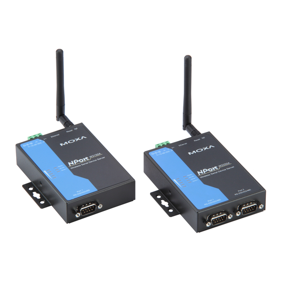
NPort W2150/2250 Plus Series User’s Manual Introduction Overview In this chapter we introduce the basic features and specifications of the NPort W2150/2250 Plus and NPort W2150/2250 Plus-T, referred to collectively as the NPort W2150/2250 Plus Series. The NPort W2150/2250 Plus Series of wireless device servers are used to connect RS- 232/422/485 serial devices such as PLCs, meters, and sensors, to a wired Ethernet LAN or wireless LAN. -
Page 13: Product Features
NPort W2150/2250 Plus Series User’s Manual Introduction Product Features Instant connection of any serial device to IEEE 802.11a/b/g network RS-232/422/485 ports supporting baudrates up to 921.6 Kbps Web-based configuration over Ethernet or WLAN Enhanced remote configuration with HTTPS, SSH Secure data access with WEP, WPA, WPA2 Built-in WLAN site survey Tool User-defined behavior for wireless roaming with signal strength thresholds Off-line port buffering and serial data log for each serial port... -
Page 14: Serial
NPort W2150/2250 Plus Series User’s Manual Introduction Serial NPort W2150 Plus: 1 port No. of Ports NPort W2250 Plus: 2 ports RS-232/422/485 Interface Port Connector 64 KB Serial Data Log 64 KB Off-Line Port Buffering Serial Communication Parameters None, Even, Odd, Space, Mark Parity 5, 6, 7, 8 Data Bits... -
Page 15: Serial Port Pin Assignments
NPort W2150/2250 Plus Series User’s Manual Introduction Serial Port Pin Assignments 1 2 3 4 5 RS-232 RS-422/ RS-485 (4W) RS-485 (2W) TxD-(A) TxD+(B) RxD+(B) Data+(B) RxD-(A) Data-(A) 6 7 8 9... -
Page 16: Chapter 2 Getting Started
Getting Started Chapter 2 The following topics are covered in this chapter: Overview Panel Layout LED Indicators Top Panel LED Indicators End Panel LED Indicators Pull High/Low Resistors for RS-422/485 Placement Options Connecting the Hardware Connecting to the Network Connecting the Power Connecting to a Serial Device... -
Page 17: Overview
NPort W2150/2250 Plus Series User’s Manual Getting Started Overview This chapter presents the hardware features of the NPort W2150/W2250 Plus Series and explains how to connect the hardware. Panel Layout NPort W2150 Plus/ NPort W2250 Plus/ NPort W2150 Plus-T NPort W2250 Plus-T 100M LED (green) 10M LED (orange) Reset... -
Page 18: Led Indicators
NPort W2150/2250 Plus Series User’s Manual Getting Started LED Indicators Top Panel LED Indicators Name Color Function Steady on: Power is on and NPort is booting up. Blinking: IP conflict or DHCP/ BOOTP server did not respond properly. Ready Steady on: NPort is functioning normally. Green Blinking: Unit is responding to Locate function. - Page 19 NPort W2150/2250 Plus Series User’s Manual Getting Started NPort W2150 Plus, NPort W2150 Plus-T NPort W2250 Plus, NPort W2250 Plus-T ATTENTION Do not use the 1 KΩ setting while in RS-232 mode. Doing so will degrade the RS-232 signals and reduce the effective communication distance.
-
Page 20: Placement Options
NPort W2150/2250 Plus Series User’s Manual Getting Started Placement Options The NPort can be placed on a desktop or other horizontal surface. You can also install the NPort on a DIN-rail or on the wall. Wall Mounting DIN-Rail Mounting Connecting the Hardware ATTENTION Before connecting the hardware, follow these important wiring safety precautions: Disconnect power source... -
Page 21: Connecting To The Network
NPort W2150/2250 Plus Series User’s Manual Getting Started The following guidelines will help ensure trouble-free signal communication with the NPort. Use separate paths to route wiring for power and devices to avoid interference. Do not run signal or communication wiring and power wiring in the same wire conduit. The rule of thumb is that wiring that shares similar electrical characteristics can be bundled together. -
Page 22: Initial Ip Configuration
Initial IP Configuration Chapter 3 The following topics are covered in this chapter: Overview Factory Default IP Using ARP to Assign IP Address Using the Telnet Console to Assign IP Address Using the Serial Console to Assign IP Address... -
Page 23: Overview
NPort W2150/2250 Plus Series User’s Manual Initial IP Configuration Overview This chapter presents several ways to assign the NPort’s IP address for the first time. Please refer to Chapter 2 for instructions on connecting to the network. The web console is the recommended method for configuring the NPort. Please refer to Chapter 5 and 6 for details on using the web console for configuration. -
Page 24: Using The Telnet Console To Assign Ip Address
NPort W2150/2250 Plus Series User’s Manual Initial IP Configuration From the DOS prompt, execute a special Telnet command using port 6000, as in the following example: telnet 192.168.200.100 6000 In this example, 192.168.200.100 is the new IP address that will be assigned to the NPort. You should see a message indicating that the connection failed. - Page 25 NPort W2150/2250 Plus Series User’s Manual Initial IP Configuration Use the cursor keys to navigate between the different fields. For IP address, Netmask, and Gateway, enter the desired values directly. For IP configuration and LAN speed, press ENTER to open a submenu and select between the available options. Press ESC to return to the menu.
-
Page 26: Using The Serial Console To Assign Ip Address
NPort W2150/2250 Plus Series User’s Manual Initial IP Configuration Using the Serial Console to Assign IP Address Before using the NPort’s serial console, turn off the power and use a serial cable to connect the NPort console port to your computer’s serial port. Port 1 on the NPort serves as the console port. is Port 1Connect to the console port with a serial-based terminal or terminal emulator program, such as Windows HyperTerminal. - Page 27 NPort W2150/2250 Plus Series User’s Manual Initial IP Configuration In your terminal emulator program, set the terminal type to ANSI or VT100. If you select Dumb Terminal as the terminal type, some of the console functions—especially the “Monitor” function—may not work properly. Hold the grave accent key (`) down and power up the NPort.
-
Page 28: Introduction To Operation Modes
Introduction to Operation Modes Chapter 4 The following topics are covered in this chapter: Overview Real COM Mode RFC2217 Mode TCP Server Mode TCP Client Mode UDP Mode Pair Connection Modes Ethernet Modem Mode Terminal Applications Terminal ASCII Mode Terminal Binary Mode Reverse Terminal Mode... -
Page 29: Overview
NPort W2150/2250 Plus Series User’s Manual Introduction to Operation Modes Overview This chapter introduces the different serial port operation modes that are available on the NPort W2150/2250 Plus Series. Each serial port on the NPort is configured independently of the other ports, with its own serial communication parameters and operation mode. -
Page 30: Rfc2217 Mode
NPort W2150/2250 Plus Series User’s Manual Introduction to Operation Modes ATTENTION Real COM drivers are installed and configured through NPort Windows Driver Manager. Real COM mode allows you to continue using your serial communications software to access devices that are now attached to your NPort device server. On the host, the NPort Real COM driver automatically intercepts data sent to the COM port, packs it into a TCP/IP packet, and redirects it to the network. -
Page 31: Tcp Client Mode
NPort W2150/2250 Plus Series User’s Manual Introduction to Operation Modes TCP Client Mode In TCP Client mode, the NPort actively TCP Client Mode establishes a TCP connection to a specific TCP/IP network host when data is received from WLAN the attached serial device. After the data has been transferred, the NPort can automatically disconnect from the host computer through the Inactivity time... -
Page 32: Pair Connection Modes
NPort W2150/2250 Plus Series User’s Manual Introduction to Operation Modes Pair Connection Modes Pair Connection Master and Slave modes Pair Connection Mode connect two NPort device servers over a Device network for serial-to-serial communication. A RS-232/422/485 NPort W2250/2150 device attached to one NPort can then Plus Slave communicate transparently to a device attached to the other NPort, as if the two devices were... -
Page 33: Terminal Applications
NPort W2150/2250 Plus Series User’s Manual Introduction to Operation Modes Terminal Applications Terminal applications involve connecting terminals to UNIX or Windows servers over a network. A terminal connects to the appropriately configured serial port the NPort, and the NPort transmits information to and from a UNIX or Windows server over the network through its Ethernet port. -
Page 34: Reverse Terminal Mode
NPort W2150/2250 Plus Series User’s Manual Introduction to Operation Modes Reverse Terminal Mode In Reverse Telnet mode, the NPort serial port is connected to a server and waits for a terminal session to from a host on the network. This is an appropriate mode for console management, with NPort serial ports connected to the console/AUX or COM ports of routers, switches, or UPS units. -
Page 35: Web Console: Basic Settings
Web Console: Basic Settings Chapter 5 The following topics are covered in this chapter: Overview Web Browser Settings Navigating the Web Console Basic Settings Server Name Server Location Time Zone Local Time Time Server... -
Page 36: Overview
NPort W2150/2250 Plus Series User’s Manual Web Console: Basic Settings Overview This chapter introduces the NPort web console and explains how to configure the basic settings. The NPort can be configured from anywhere on the network through its web console. Simply point the browser to the device server’s IP address to open the web console. -
Page 37: Navigating The Web Console
NPort W2150/2250 Plus Series User’s Manual Web Console: Basic Settings Navigating the Web Console To open the web console, enter your device server’s IP address in the website address line. If you are configuring the NPort for the first time over an Ethernet cable, you will use the default IP address, 192.168.126.254. -
Page 38: Basic Settings
NPort W2150/2250 Plus Series User’s Manual Web Console: Basic Settings Basic Settings On the Basic Settings page, you can configure Server name, Server location, Time zone (24- hour), Local time, and Time server. Server Name NPW2150P_<serial no.> or NPW2250P_<serial no.> Default free text (e.g., “Server 1”) Options... -
Page 39: Local Time
NPort W2150/2250 Plus Series User’s Manual Web Console: Basic Settings Local Time Default Date (yy:mm:dd), Time (hh:mm:ss) Options The NPort has a built-in real-time clock that allows you to add time information Description to functions such as the automatic warning e-mail or SNMP trap. This field shows the current time according to the NPort’s built-in real-time clock. -
Page 40: Web Console: Network Settings
Web Console: Network Settings Chapter 6 The following topics are covered in this chapter: Overview Security Settings for WLAN Profile Authentication Network Settings> General Settings DNS Server 1 and 2 Encryption WINS Function PSK Passphrase WINS Server Security Settings for WEP Encryption WEP Key Length Network Settings>... -
Page 41: Overview
NPort W2150/2250 Plus Series User’s Manual Web Console: Network Settings Overview This chapter explains how to configure all settings located under the Network Settings folder in the NPort web console. Network Settings> General Settings On the General Settings page in the Network Settings folder, you can modify DNS server 1 and 2, WINS function, and WINS server. -
Page 42: Wins Function
NPort W2150/2250 Plus Series User’s Manual Web Console: Network Settings WINS Function Enable Default Enable, Disable Options This field enables or disables the WINS (Windows Internet Naming Service) Description server. TCP/IP uses IP addresses to identify hosts, but users often use symbolic names, such as computer names. -
Page 43: Ip Configuration
NPort W2150/2250 Plus Series User’s Manual Web Console: Network Settings IP Configuration Static Default Static, DHCP, DHCP/BOOTP, BOOTP Options This field determines how the NPort’s IP address will be assigned. Description Static: IP address, netmask, and gateway are user-defined. DHCP: IP address, netmask, gateway, DNS, and time server are assigned by DHCP server. -
Page 44: Speed
NPort W2150/2250 Plus Series User’s Manual Web Console: Network Settings Speed Auto Default Auto, 10Mbps Half, 10Mbps Full, 100Mbps Half, 100Mbps Full Options This field specifies the network speed for the built-in Ethernet connection. Description IEEE802.3 Ethernet supports auto negotiation of transfer speed. However, some switches/hubs require that the communication speed be fixed at 100Mbps or 10Mbps. -
Page 45: Ip Configuration
NPort W2150/2250 Plus Series User’s Manual Web Console: Network Settings IP Configuration Static Default Static, DHCP, DHCP/BOOTP, BOOTP Options This field determines how the NPort’s IP address will be assigned. Description Static: IP address, netmask, and gateway are user-defined. DHCP: IP address, netmask, gateway, DNS, and time server are assigned by DHCP server. -
Page 46: Network Settings> Wlan Settings> Profile
NPort W2150/2250 Plus Series User’s Manual Web Console: Network Settings Network Settings> WLAN Settings> Profile The Profile page is located under WLAN Settings in the Network Settings folder. This is where you configure the NPort for Ad-hoc or Infrastructure operation. Different settings are available depending on whether you select Ad-hoc Mode or Infrastructure Mode. -
Page 47: Network Type
NPort W2150/2250 Plus Series User’s Manual Web Console: Network Settings Network Type Infrastructure Mode Default Infrastructure Mode, Ad-hoc Mode Options This field specifies whether the NPort will operate in Ad-hoc or Infrastructure Description Mode. For all wireless networking devices, there are two possible modes for communication with another wireless device. -
Page 48: Priority
NPort W2150/2250 Plus Series User’s Manual Web Console: Network Settings Priority Profile 1 Default Profile 2 Profile 3 Profile 1, Profile 2, and Profile 3 in any order Options This field is only available in Infrastructure Mode and is used to set the Description priorities of the three available profiles. -
Page 49: General Settings For Wlan Profile
NPort W2150/2250 Plus Series User’s Manual Web Console: Network Settings General Settings for WLAN Profile The General page is opened through the Profile page, under WLAN Settings in the Network Settings folder. After selecting Ad-hoc or Infrastructure Mode, click [General] to open the General page for the selected profile. -
Page 50: Profile Name
NPort W2150/2250 Plus Series User’s Manual Web Console: Network Settings In Infrastructure Mode On the General page, you can configure Profile name, Operation mode, and SSID. Additional settings are also available depending on whether you select Ad-hoc Mode or Infrastructure Mode. Profile Name Ad-hoc (in Ad-hoc Mode) Default... -
Page 51: Operation Mode
NPort W2150/2250 Plus Series User’s Manual Web Console: Network Settings Operation Mode Auto Default Auto, 802.11a, 802.11b, 802.11g Options This field determines which wireless standard will be used by the selected Description profile. 802.11a, 802.11b, and 802.11g are supported. Auto: In Ad-hoc Mode, the NPort will scan the 2.4G wireless band and will automatically select the appropriate wireless standard for communication with any other wireless devices that are detected. -
Page 52: Security Settings For Wlan Profile
NPort W2150/2250 Plus Series User’s Manual Web Console: Network Settings Security Settings for WLAN Profile The Security page is opened through the Profile page, under WLAN Settings in the Network Settings folder. After selecting Ad-hoc or Infrastructure Mode, click [Security] to open the Security page for the selected profile. - Page 53 NPort W2150/2250 Plus Series User’s Manual Web Console: Network Settings In Infrastructure Mode You will need to configure Authentication and Encryption. These settings must match the settings on the wireless device at the other end of the connection (such as the AP). Different settings and options are available depending on how Authentication and Encryption are configured.
-
Page 54: Authentication
NPort W2150/2250 Plus Series User’s Manual Web Console: Network Settings Authentication Open System Default Open System, Shared Key, WPA, WPA-PSK, WPA2, WPA2-PSK Options This field specifies how wireless devices will be authenticated. Only Description authenticated devices will be allowed to communicate with the NPort. If a RADIUS server is used, this setting must match the setting on the RADIUS server. -
Page 55: Encryption
NPort W2150/2250 Plus Series User’s Manual Web Console: Network Settings Encryption Disable Default Disable, WEP, TKIP, AES-CCMP Options This field specifies the type of encryption to use during wireless Description communication. Different encryption methods are available depending on the Authentication setting. Also, each encryption method has its own set of parameters that may also require configuration. -
Page 56: Security Settings For Wep Encryption
NPort W2150/2250 Plus Series User’s Manual Web Console: Network Settings Security Settings for WEP Encryption When Encryption is set to WEP on the Security page for the WLAN profile, you will be able to configure WEP key length, WEP key index, and WEP key source. Other settings will be displayed depending on how WEP key source is configured. -
Page 57: Wep Key Source
NPort W2150/2250 Plus Series User’s Manual Web Console: Network Settings WEP Key Source Manual Default Manual, Generate WEP keys by passphrase Options This field specifies whether the WEP key will be generated manually or through Description a user-specified passphrase. A passphrase is equivalent to a free-text password that will be used to generate the WEP key. -
Page 58: Security Settings For Wpa, Wpa2
NPort W2150/2250 Plus Series User’s Manual Web Console: Network Settings Security Settings for WPA, WPA2 When WPA or WPA2 is used for authentication, you will also need to configure EAP method in the Security settings for the WLAN profile. Other settings will also be displayed depending on how EAP method is configured. -
Page 59: Eap Method
NPort W2150/2250 Plus Series User’s Manual Web Console: Network Settings EAP Method PEAP Default TLS, PEAP, TTLS, LEAP Options This field specifies the EAP method to use for authentication. Four methods are Description supported. TLS: Transport Layer Security (TLS) was created by Microsoft and accepted by the IETF as RFC 2716: PPP EAP TLS Authentication Protocol. -
Page 60: Anonymous Username
NPort W2150/2250 Plus Series User’s Manual Web Console: Network Settings Anonymous Username Default free text (e.g., “Anyuser”) Options This field specifies the anonymous username to use when initiating Description authentication. After the RADIUS Server has been verified by certificate, the true username and password will be used to complete the authentication process. -
Page 61: Network Settings> Advanced Settings
NPort W2150/2250 Plus Series User’s Manual Web Console: Network Settings Network Settings> Advanced Settings On the Advanced Settings page in the Network Settings folder, you can modify Gratuitous ARP. Gratuitous ARP Disabled Default Disabled, Enabled, 10 to 1000 sec Options This field specifies how often the NPort sends broadcast packets to update the Description ARP table. -
Page 62: Web Console: Serial Port Settings
Web Console: Serial Port Settings Chapter 7 The following topics are covered in this chapter: Overview Settings for TCP Server Mode TCP Alive Check Time Serial Port Settings> Port 1 or 2> Operation Modes Inactivity Time Application Max Connection Mode Ignore Jammed IP Settings for RealCOM Mode Allow Driver Control... - Page 63 NPort W2150/2250 Plus Series User’s Manual Web Console: Serial Port Settings Settings for UDP Mode Settings for Terminal Binary Mode Destination Address 1 to 4 TCP Alive Check Time Local Listen Port Inactivity Time Packet Length Auto-Link Protocol Delimiter 1 and 2 Primary and Secondary Host Address Delimiter Process Telnet TCP Port...
-
Page 64: Overview
NPort W2150/2250 Plus Series User’s Manual Web Console: Serial Port Settings Overview This chapter explains how to configure all settings located under the Serial Port Settings folder in the NPort web console. Serial Port Settings> Port 1 or 2> Operation Modes Each serial port on the NPort is configured in its own folder under the Serial Port Settings folder. -
Page 65: Application
NPort W2150/2250 Plus Series User’s Manual Web Console: Serial Port Settings Application Disable Default Disable, Device Control, Socket, Pair Connection, Ethernet Modem, Terminal, Options Reverse Terminal This field specifies what kind application you will be using for this serial port. Description Depending on the application, different operation modes and related settings will be displayed. -
Page 66: Mode
NPort W2150/2250 Plus Series User’s Manual Web Console: Serial Port Settings Mode (depends on Application) Default RealCOM, RFC2217, TCP Server, TCP Client, UDP, Pair Connection Master, Options Pair Connection Slave, Terminal (TERM_ASC), Terminal (TERM_BIN) Along with Application, this field specifies the serial port’s operation mode, or Description how it will interact with network devices. -
Page 67: Settings For Realcom Mode
NPort W2150/2250 Plus Series User’s Manual Web Console: Serial Port Settings Settings for RealCOM Mode When Mode is set to RealCOM on a serial port’s Operation Modes page, you will be able to configure additional settings such as TCP alive check time, Max connection, and Ignore jammed IP. -
Page 68: Max Connection
NPort W2150/2250 Plus Series User’s Manual Web Console: Serial Port Settings Max Connection Default 1 to 4 Options This field specifies the maximum number of connections that will be accepted Description by the serial port. 1: Only one specific host can access this serial port, and the Real COM driver on that host will have full control over the port. -
Page 69: Allow Driver Control
NPort W2150/2250 Plus Series User’s Manual Web Console: Serial Port Settings Allow Driver Control Disable Default Disable, Enable Options This field specifies how the port will proceed if driver control commands are Description received from multiple hosts that are connected to the port. Disable: Driver control commands will be ignored. -
Page 70: Delimiter 1 And 2
NPort W2150/2250 Plus Series User’s Manual Web Console: Serial Port Settings Delimiter 1 and 2 Disabled Default Disabled, Enabled, 00 to FF Options These fields are used to define special delimiter character(s) for data packing. Description Enable Delimiter 1 to control data packing with a single character; enable both Delimiter 1 and 2 to control data packing with two characters received in sequence. -
Page 71: Force Transmit
NPort W2150/2250 Plus Series User’s Manual Web Console: Serial Port Settings Force Transmit 0 ms Default 0 to 65535 Options This field controls data packing by the amount of time that elapses between bits Description of data. When using this field, make sure that Inactivity time is disabled or set to a larger value. -
Page 72: Tcp Alive Check Time
NPort W2150/2250 Plus Series User’s Manual Web Console: Serial Port Settings TCP Alive Check Time 7 min Default 0 to 99 min Options This field specifies how long the NPort will wait for a response to “keep alive” Description packets before closing the TCP connection. The NPort checks connection status by sending periodic “keep alive”... -
Page 73: Delimiter Process
NPort W2150/2250 Plus Series User’s Manual Web Console: Serial Port Settings ATTENTION When Delimiter 1 is enabled, Packet length must be set to 0. Delimiter Process Do Nothing Default Do Nothing, Delimiter + 1, Delimiter + 2, Strip Delimiter Options This field specifies how data is packed when delimiter characters are received. -
Page 74: Settings For Tcp Server Mode
NPort W2150/2250 Plus Series User’s Manual Web Console: Serial Port Settings Settings for TCP Server Mode When Mode is set to TCP Server on a serial port’s Operation Modes page, you will be able to configure additional settings such as TCP alive check time, Inactivity time, and Max connection. TCP Alive Check Time 7 min Default... -
Page 75: Inactivity Time
NPort W2150/2250 Plus Series User’s Manual Web Console: Serial Port Settings Inactivity Time 0 ms Default 0 to 65535 ms Options This field specifies the time limit for keeping the connection open if no data Description flows to or from the serial device. 0: The connection will remain open even if data is never received. -
Page 76: Allow Driver Control
NPort W2150/2250 Plus Series User’s Manual Web Console: Serial Port Settings Allow Driver Control Disable Default Disable, Enable Options This field specifies how the port will proceed if driver control commands are Description received from multiple hosts that are connected to the port. Disable: Driver control commands will be ignored. -
Page 77: Packet Length
NPort W2150/2250 Plus Series User’s Manual Web Console: Serial Port Settings Packet Length Default 0 to 1024 Options This field specifies the maximum amount of data that is allowed to accumulate Description in the serial port buffer before sending. 0: Packet length is disregarded and data in the buffer will be sent as specified by the delimiter settings or when the buffer is full. -
Page 78: Delimiter Process
NPort W2150/2250 Plus Series User’s Manual Web Console: Serial Port Settings Delimiter Process Do Nothing Default Do Nothing, Delimiter + 1, Delimiter + 2, Strip Delimiter Options This field specifies how data is packed when delimiter characters are received. Description This field has no effect if Delimiter 1 is not enabled. -
Page 79: Settings For Tcp Client Mode
NPort W2150/2250 Plus Series User’s Manual Web Console: Serial Port Settings Settings for TCP Client Mode When Mode is set to TCP Client on a serial port’s Operation Modes page, you will be able to configure additional settings such as TCP alive check time, Inactivity time, and Ignore jammed TCP Alive Check Time 7 min Default... -
Page 80: Inactivity Time
NPort W2150/2250 Plus Series User’s Manual Web Console: Serial Port Settings Inactivity Time 0 ms Default 0 to 65535 ms Options This field specifies the time limit for keeping the connection open if no data Description flows to or from the serial device. 0: The TCP connection will be kept active until a connection close request is received, even if data is never received. -
Page 81: Designated Local Port 1 To 4
NPort W2150/2250 Plus Series User’s Manual Web Console: Serial Port Settings Designated Local Port 1 to 4 Default 1 to 65535 Options This field specifies the TCP port number that will be used for data transmission Description with the serial port. Connection Control Startup/None Default... -
Page 82: Delimiter 1 And 2
NPort W2150/2250 Plus Series User’s Manual Web Console: Serial Port Settings Delimiter 1 and 2 Disabled Default Disabled, Enabled, 00 to FF Options These fields are used to define special delimiter character(s) for data packing. Description Enable Delimiter 1 to control data packing with a single character; enable both Delimiter 1 and 2 to control data packing with two characters received in sequence. -
Page 83: Force Transmit
NPort W2150/2250 Plus Series User’s Manual Web Console: Serial Port Settings Force Transmit 0 ms Default 0 to 65535 Options This field controls data packing by the amount of time that elapses between bits Description of data. When using this field, make sure that Inactivity time is disabled or set to a larger value. -
Page 84: Destination Address 1 To 4
NPort W2150/2250 Plus Series User’s Manual Web Console: Serial Port Settings Destination Address 1 to 4 Default IP address range and port (e.g., “192.168.1.1” to “192.168.1.64” and “4001”) Options In UDP mode, you may specify up to 4 ranges of IP addresses for the serial port Description to connect to. -
Page 85: Delimiter Process
NPort W2150/2250 Plus Series User’s Manual Web Console: Serial Port Settings ATTENTION When Delimiter 1 is enabled, Packet length must be set to 0. Delimiter Process Do Nothing Default Do Nothing, Delimiter + 1, Delimiter + 2, Strip Delimiter Options This field specifies how data is packed when delimiter characters are received. -
Page 86: Settings For Pair Connection Modes
NPort W2150/2250 Plus Series User’s Manual Web Console: Serial Port Settings Settings for Pair Connection Modes When Application is set to Pair Connection on a serial port’s Operation Modes page, you will be able to configure Pair Connection Master and Slave mode settings. A Pair Connection application involves one serial port communicating over an IP network to another serial port as if the two serial ports were connected by a serial cable. -
Page 87: Destination Address
NPort W2150/2250 Plus Series User’s Manual Web Console: Serial Port Settings Destination Address Default IP address and port (e.g., “192.168.1.1” and “4001”) Options This field specifies the IP address for the NPort at the opposite end of the Pair Description Connection, and the TCP port number for communication with the serial port. -
Page 88: Tcp Port
NPort W2150/2250 Plus Series User’s Manual Web Console: Serial Port Settings TCP Port 4001 Default 0 to 9999 Options This field specifies the TCP port to use for communication with the attached Description serial device. Settings for Terminal ASCII Mode When Mode is set to Terminal (TERM_ASC) on a serial port’s Operation Modes page, you will be able to configure additional settings such as TCP alive check time, Inactivity time, and Auto- link protocol. -
Page 89: Tcp Alive Check Time
NPort W2150/2250 Plus Series User’s Manual Web Console: Serial Port Settings TCP Alive Check Time 7 min Default 0 to 99 min Options This field specifies how long the NPort will wait for a response to “keep alive” Description packets before closing the TCP connection. The NPort checks connection status by sending periodic “keep alive”... -
Page 90: Primary And Secondary Host Address
NPort W2150/2250 Plus Series User’s Manual Web Console: Serial Port Settings Primary and Secondary Host Address Default IP address (e.g., “192.168.1.1”) Options These fields designate permanent hosts to which the terminal will always be Description connected. Auto-Link Protocol must be configured to Telnet or Rlogin in order to specify a permanent host. -
Page 91: Interrupt
NPort W2150/2250 Plus Series User’s Manual Web Console: Serial Port Settings Interrupt Default Options This field defines the quick key for terminating the program. Description Authentication Type None Default None, Local, RADIUS Options This field specifies the method used to verify a user’s ID and authorization. Description None: No authentication is required to open a terminal session. -
Page 92: Login Password
NPort W2150/2250 Plus Series User’s Manual Web Console: Serial Port Settings Login Password Default free text (e.g., “Password123”) Options This field specifies how the NPort will respond when prompted for a password Description to log in for a terminal session. The NPort will automatically respond with the specified password when it receives the Password Prompt. -
Page 93: Tcp Alive Check Time
NPort W2150/2250 Plus Series User’s Manual Web Console: Serial Port Settings TCP Alive Check Time 7 min Default 0 to 99 min Options This field specifies how long the NPort will wait for a response to “keep alive” Description packets before closing the TCP connection. The NPort checks connection status by sending periodic “keep alive”... -
Page 94: Primary And Secondary Host Address
NPort W2150/2250 Plus Series User’s Manual Web Console: Serial Port Settings Primary and Secondary Host Address Default IP address (e.g., “192.168.1.1”) Options These fields designate permanent hosts to which the terminal will always be Description connected. Auto-Link Protocol must be configured to Telnet or Rlogin in order to specify a permanent host. -
Page 95: Auto-Login Prompt
NPort W2150/2250 Plus Series User’s Manual Web Console: Serial Port Settings Auto-login Prompt ogin: Default free text (e.g., “Login prompt:”) Options This field specifies what the login prompt for the terminal session will be for Description automatic login purposes. The NPort can automatically enter the username and password for a terminal session. -
Page 96: Settings For Reverse Terminal Mode
NPort W2150/2250 Plus Series User’s Manual Web Console: Serial Port Settings Settings for Reverse Terminal Mode When Application is set to Reverse Terminal on a serial port’s Operation Modes page, you will be able to configure additional settings such as TCP alive check time, Inactivity time, and TCP port. -
Page 97: Tcp Port
NPort W2150/2250 Plus Series User’s Manual Web Console: Serial Port Settings TCP Port 4001 Default 0 to 9999 Options This field specifies the TCP port number for reverse terminal sessions. Description Authentication Type None Default None, Local, RADIUS Options This field specifies the method used to verify a user’s ID and authorization. Description None: No authentication is required to open a terminal session. -
Page 98: Serial Port Settings> Port 1 Or 2> Communication Parameters
NPort W2150/2250 Plus Series User’s Manual Web Console: Serial Port Settings Serial Port Settings> Port 1 or 2> Communication Parameters Each serial port on the NPort is configured in its own folder under the Serial Port Settings folder. The Communication Parameters page for each serial port is where serial communication settings are specified, such as Baud rate, Data bits, and Stop bits. -
Page 99: Baud Rate
NPort W2150/2250 Plus Series User’s Manual Web Console: Serial Port Settings Baud Rate 115200 Default 50, 75, 110, 134, 150, 300, 600, 1200, 1800, 2400, 4800, 7200, 9600, 19200, Options 38400, 57600, 115200, 230400, 460800, 921600, Other This field specifies the baudrate for the serial port. Nonstandard baudrates are Description supported through the “Other”... -
Page 100: Serial Port Settings> Port 1 Or 2> Data Buffering/Log
NPort W2150/2250 Plus Series User’s Manual Web Console: Serial Port Settings Serial Port Settings> Port 1 or 2> Data Buffering/Log Each serial port on the NPort is configured in its own folder under the Serial Port Settings folder. On the serial port’s Data Buffering/Log page, you can enable or disable Port buffering and Serial data logging. -
Page 101: Serial Port Settings> Welcome Message
NPort W2150/2250 Plus Series User’s Manual Web Console: Serial Port Settings Serial Port Settings> Welcome Message On the Welcome Message page in the Serial Port Settings folder, you can enable and enter a welcome message to greet terminal users. 7-40... -
Page 102: Web Console: System Management
Web Console: System Management Chapter 8 The following topics are covered in this chapter: Overview System Management> Misc. Network Settings> Accessible IP List System Management> Misc. Network Settings> SNMP Agent Settings SNMP Read Community String Write Community String Contact Name Location SNMP Agent Version Read Only User Name... - Page 103 NPort W2150/2250 Plus Series User’s Manual Web Console: System Management System Management> Auto Warning Settings> E-mail Alert Mail Server From E-mail Address To E-mail Address 1 to 4 System Management> Auto Warning Settings> SNMP Trap SNMP Trap Server IP Trap Version Trap Community System Management>...
-
Page 104: Overview
NPort W2150/2250 Plus Series User’s Manual Web Console: System Management Overview This chapter explains how to configure all settings located under the System Management folder in the NPort web console. System Management> Misc. Network Settings> Accessible IP List The Accessible IP List page is located under Misc. Network Settings in the System Management folder. -
Page 105: System Management> Misc. Network Settings> Snmp Agent Settings
NPort W2150/2250 Plus Series User’s Manual Web Console: System Management Refer to the following table for more configuration examples. Desired IP Range IP Address Field Netmask Field Any host Disable Disable 192.168.1.120 192.168.1.120 255.255.255.255 192.168.1.1 to 192.168.1.254 192.168.1.0 255.255.255.0 192.168.0.1 to 192.168.255.254 192.168.0.0 255.255.0.0 192.168.1.1 to 192.168.1.126... -
Page 106: Read Community String
NPort W2150/2250 Plus Series User’s Manual Web Console: System Management Read Community String public Default free text (e.g., “public community”) Options This field specifies the read community string used for the SNMP Agent. This is Description a text password mechanism that is used to weakly authenticate queries to agents of managed network devices. -
Page 107: Read Only Password
NPort W2150/2250 Plus Series User’s Manual Web Console: System Management Read Only Password Default free text (e.g., “password123”) Options This field specifies the password that users must enter for read-only access, if Description read only authentication is enabled. Read Only Privacy mode Disable Default Disable, DES_CBC... -
Page 108: System Management> Misc. Network Settings> Host Table
NPort W2150/2250 Plus Series User’s Manual Web Console: System Management System Management> Misc. Network Settings> Host Table The Host Table page is located under Misc. Network Settings in the System Management folder. This page is used to assign host names to IP addresses, for use on the web console. You may then use the host name instead of the IP address for certain fields on the web console. -
Page 109: System Management> Misc. Network Settings> User Table
NPort W2150/2250 Plus Series User’s Manual Web Console: System Management System Management> Misc. Network Settings> User Table The User Table page is located under Misc. Network Settings in the System Management folder. This page is used for local authentication of users for terminal or reverse terminal access. It is a convenient option if your system does not rely on an external RADIUS server for authentication. -
Page 110: Radius Server Ip
NPort W2150/2250 Plus Series User’s Manual Web Console: System Management RADIUS Server IP Default IP address (e.g., “192.168.2.2”) Options This field specifies the IP address of the RADIUS server. Description RADIUS Key Default free text (e.g., “authenticate123”) Options This field specifies the password that is used by the RADIUS server. Description UDP Port 1645... -
Page 111: System Management> Auto Warning Settings> Event Settings
NPort W2150/2250 Plus Series User’s Manual Web Console: System Management Group Event System System Cold Start, System Warm Start Network DHCP/BOOTP, Get IP/Renew, NTP, Mail Fail, NTP Connect Fail, DHCP Fail, IP Conflict, Config Import, Config Export Config Login Fail, IP Changed, Password Changed, Config Changed, Firmware Upgrade, SSL Key Improt, Config Import, Config Export Op Mode Connect, Disconnect, Authentication Fail, Restart... -
Page 112: System Management> Auto Warning Settings> Serial Event Settings
NPort W2150/2250 Plus Series User’s Manual Web Console: System Management System Management> Auto Warning Settings> Serial Event Settings The Serial Event Settings page is located under Auto Warning Settings in the System Management folder. This is where you specify how the NPort will notify you of DCD and DSR events for each serial port. -
Page 113: System Management> Auto Warning Settings> E-Mail Alert
NPort W2150/2250 Plus Series User’s Manual Web Console: System Management System Management> Auto Warning Settings> E- mail Alert The E-mail Alert page is located under Auto Warning Settings in the System Management folder. This is where you specify how and where e-mail is sent when e-mail is used for automatic notification of system and serial port events. -
Page 114: To E-Mail Address 1 To 4
NPort W2150/2250 Plus Series User’s Manual Web Console: System Management To E-mail Address 1 to 4 Default free text (e.g., “admin@abc.com”) Options These fields specify the destination e-mail address(es) for the automatic e-mail Description warnings. System Management> Auto Warning Settings> SNMP Trap The SNMP Trap page is located under Auto Warning Settings in the System Management folder. -
Page 115: System Management> Maintenance> Console Settings
NPort W2150/2250 Plus Series User’s Manual Web Console: System Management System Management> Maintenance> Console Settings The Console Settings page is located under Maintenance in the System Management folder. This is where you enable or disable access to the various NPort configuration consoles, as well as the behavior of the reset button. -
Page 116: Reset Button
NPort W2150/2250 Plus Series User’s Manual Web Console: System Management Reset Button Always Enable Default Always Enable, Disable after 60 sec Options This field specifies the behavior of the hardware reset button. Description Always Enable: The reset button will be operate as usual. Disable after 60 sec: The reset button will only be effective for the first 60 seconds that the NPort is powered on. -
Page 117: System Management> Maintenance> Firmware Upgrade
NPort W2150/2250 Plus Series User’s Manual Web Console: System Management System Management> Maintenance> Firmware Upgrade The Firmware Upgrade page is located under Maintenance in the System Management folder. This is where you can update the NPort firmware. After obtaining the latest firmware from www.moxa.com, select or browse for the firmware file in the Select firmware file field. -
Page 118: System Management> Maintenance> Configuration Export
NPort W2150/2250 Plus Series User’s Manual Web Console: System Management System Management> Maintenance> Configuration Export The Configuration Export page is located under Maintenance in the System Management folder. This is where you can save the NPort’s current configuration to a file on the local host. Click [Download] to begin the process. -
Page 119: System Management> Maintenance> Change Password
NPort W2150/2250 Plus Series User’s Manual Web Console: System Management System Management> Maintenance> Change Password The Change Password page is located under Maintenance in the System Management folder. To change the password, first enter the old password in the Old password field. Leave this blank if the NPort is not currently password-protected. -
Page 120: System Management> Certificate> Ethernet Ssl Certificate Import
NPort W2150/2250 Plus Series User’s Manual Web Console: System Management System Management> Certificate> Ethernet SSL Certificate Import The Ethernet SSL Certificate Import page is located under Certificate in the System Management folder. This is where you can load the Ethernet SSL certificate. Select or browse for the certificate file in the Select SSL certificate/key file field. -
Page 121: System Management> Certificate> Wpa Server Certificate Import
NPort W2150/2250 Plus Series User’s Manual Web Console: System Management System Management> Certificate> WPA Server Certificate Import The WPA Server Certificate Import page is located under Certificate in the System Management folder. This is where you can load the WPA server certificate. Select or browse for the certificate file in the Select WPA server certificate file field. -
Page 122: System Management> Certificate> Wpa User Certificate Import
NPort W2150/2250 Plus Series User’s Manual Web Console: System Management System Management> Certificate> WPA User Certificate Import The WPA User Certificate Import page is located under Certificate in the System Management folder. This is where you can load the WPA user certificate. Select or browse for the certificate file in the Select WPA user certificate file field. -
Page 123: System Management> Certificate> Wpa User Key Import
NPort W2150/2250 Plus Series User’s Manual Web Console: System Management System Management> Certificate> WPA User Key Import The WPA User Key Import page is located under Certificate in the System Management folder. This is where you can load the WPA user certificate. Select or browse for the user private key file in the Select WPA user privacy key file field and enter the Password for the private key. -
Page 124: System Management> Certificate> Certificate/Key Delete
NPort W2150/2250 Plus Series User’s Manual Web Console: System Management System Management> Certificate> Certificate/Key Delete The Certificate/Key Delete page is located under Certificate in the System Management folder. This page is where you can delete certificates or WPA keys that have been installed on the model. When you click [Submit], any certificate or key that has been set to “Delete”... -
Page 125: Web Console: System Monitoring
Web Console: System Monitoring Chapter 9 The following topics are covered in this chapter: Overview System Monitoring> Serial Status> Serial to Network Connections System Monitoring> Serial Status> Serial Port Status System Monitoring> Serial Status> Serial Port Error Count System Monitoring> Serial Status> Serial Port Settings System Monitoring>... -
Page 126: Overview
NPort W2150/2250 Plus Series User’s Manual Web Console: System Monitoring Overview This chapter explains how to use the System Monitoring functions on the NPort web console. These functions allow you to monitor many different aspects of operation. System Monitoring> Serial Status> Serial to Network Connections The Serial to Network Connections page is located under Serial Status in the System Monitoring folder. -
Page 127: System Monitoring> Serial Status> Serial Port Error Count
NPort W2150/2250 Plus Series User’s Manual Web Console: System Monitoring RxTotalCnt: number of Rx packets since the NPort was powered on Buffering: the number of packets that are currently queued in the off-line port buffer System Monitoring> Serial Status> Serial Port Error Count The Serial Port Error Count page is located under Serial Status in the System Monitoring folder. -
Page 128: System Monitoring> System Status> Network Connections
NPort W2150/2250 Plus Series User’s Manual Web Console: System Monitoring System Monitoring> System Status> Network Connections The Network Connections page is located under System Status in the System Monitoring folder. On this page, you can view the current status of any network connection to the NPort. System Monitoring>... -
Page 129: System Monitoring> System Status> Serial Data Log
NPort W2150/2250 Plus Series User’s Manual Web Console: System Monitoring System Monitoring> System Status> Serial Data Log Data logs for each serial port can be viewed in ASCII or HEX format. After selecting the serial port and format, you may click Select all to select the entire log if you wish to copy and paste the contents into a text file. -
Page 130: System Monitoring> System Status> System Log
NPort W2150/2250 Plus Series User’s Manual Web Console: System Monitoring System Monitoring> System Status> System Log The System Log page is located under System Status in the System Monitoring folder. This is where you can view the log of NPort system events. Click [Select all] to select the entire log if you wish to copy and paste the contents into a text file. -
Page 131: System Monitoring> System Status> Wlan Status
NPort W2150/2250 Plus Series User’s Manual Web Console: System Monitoring System Monitoring> System Status> WLAN Status The WLAN Status page is located under System Status in the System Monitoring folder. This is where you can view the current WLAN settings and status. System Monitoring>... - Page 132 NPort W2150/2250 Plus Series User’s Manual Web Console: System Monitoring The WLAN Site Survey page is located under System Status in the System Monitoring folder. This is where you can view live data on wireless signal strength and characteristics. It is useful tool to help you complete a wireless site survey without installing additional software.
- Page 133 NPort W2150/2250 Plus Series User’s Manual Web Console: System Monitoring Please note that Java must be enabled in your web browser for the WLAN Site Survey page to display properly.
-
Page 134: Web Console: Save And Restart
Web Console: Save and Restart Chapter 10 The following topics are covered in this chapter: Overview Save Configuration Restart> Restart System Restart> Restart Portss... -
Page 135: Overview
NPort W2150/2250 Plus Series User’s Manual Web Console: Save and Restart Overview This chapter explains how to use save your configuration changes and restart the NPort using the NPort web console. Configuration changes will not be effective until they are saved and the NPort is rebooted. -
Page 136: Restart> Restart Ports
NPort W2150/2250 Plus Series User’s Manual Web Console: Save and Restart Restart> Restart Ports The Restart Ports page is located in the Restart folder. Select the desired serial ports, or click [Select All] to select all serial ports. Click [Submit] to restart the selected serial ports. 10-3... -
Page 137: Installing And Configuring The Software
Installing and Configuring the Software Chapter 11 The following topics are covered in this chapter: Overview NPort Windows Driver Manager Installing NPort Windows Driver Manager Adding Mapped Serial Ports Configuring Mapped Serial Ports NPort Search Utility Installing NPort Search Utility Finding NPort Device Servers on Network Modifying NPort IP Addresses Upgrading NPort Firmware... -
Page 138: Overview
NPort W2150/2250 Plus Series User’s Manual Installing and Configuring the Software Overview This chapter describes how to install and use NPort Windows Driver Manager, NPort Search Utility, and NPort Linux and UNIX drivers. These items are located on the Document & Software CD that is provided with the NPort W2150/2250 Plus Series. - Page 139 NPort W2150/2250 Plus Series User’s Manual Installing and Configuring the Software 3. Select a destination directory and click [Next] to proceed. 4. Select a folder for the program shortcuts and click [Next] to proceed. 11-3...
- Page 140 NPort W2150/2250 Plus Series User’s Manual Installing and Configuring the Software 5. Verify the installation parameters and click Install to proceed. 6. If you see a warning that the software has not passed Windows Logo testing, click [Continue Anyway] to proceed. 11-4...
-
Page 141: Adding Mapped Serial Ports
NPort W2150/2250 Plus Series User’s Manual Installing and Configuring the Software 7. The wizard will begin installing the files. When the files have been installed, click [Finish] to complete the installation. Adding Mapped Serial Ports NPort Windows Driver Manager adds a COM port to your PC that is mapped to an NPort serial port. - Page 142 NPort W2150/2250 Plus Series User’s Manual Installing and Configuring the Software 2. Click [Rescan] to search the network for NPort device servers. In the list of NPort device servers that are found, select the unit(s) that you will use for COM mapping and click [OK]. Alternatively, you can select Input Manually and manually enter the NPort IP Address, 1st Data Port, 1st Command Port, and Total Ports for the desired NPort unit.
- Page 143 NPort W2150/2250 Plus Series User’s Manual Installing and Configuring the Software 3. NPort Windows Driver Manager will list each available serial port and will automatically assign a new COM port to each one. The new COM port will not be accessible by the host system until it has been activated in NPort Windows Driver Manager.
-
Page 144: Configuring Mapped Serial Ports
NPort W2150/2250 Plus Series User’s Manual Installing and Configuring the Software Configuring Mapped Serial Ports 1. To modify the settings of a mapped serial port, select the desired port(s) and click [Setting] on the main toolbar. 2. On the Basic Setting tab, select the COM Number that will be assigned to the serial port. If you have selected multiple ports, you can assign COM numbers automatically in sequential order by selecting the “Auto Enumerating”... - Page 145 NPort W2150/2250 Plus Series User’s Manual Installing and Configuring the Software 3. On the Advanced Setting tab, configure Tx Mode, FIFO, and Fast Flush. Tx Mode: In Hi-Performance mode, the driver immediately issues a “Tx Empty” response to the program after sending data to the NPort. In Classical mode, the driver sends the “Tx Empty”...
- Page 146 NPort W2150/2250 Plus Series User’s Manual Installing and Configuring the Software 4. On the Serial Parameters tab, specify the communication settings that the host will use when opening the COM port. 5. On the Security tab, select the Enable Data Encryption option to enable data to be encrypted when transmitted over the COM ports.
-
Page 147: Nport Search Utility
NPort W2150/2250 Plus Series User’s Manual Installing and Configuring the Software 7. To save all COM mapping settings to a text file, right-click a COM port and select Export in the context menu. After the settings have been exported to a file, they can be imported on another host. - Page 148 NPort W2150/2250 Plus Series User’s Manual Installing and Configuring the Software 3. Select a destination directory and click [Next] to proceed. 4. Indicate if you wish to create a desktop icon and click [Next] to proceed. 11-12...
- Page 149 NPort W2150/2250 Plus Series User’s Manual Installing and Configuring the Software 5. Verify the installation parameters and click Install to proceed. 6. The wizard will begin installing the files. After the files have been installed, click [Finish] to complete the installation. 11-13...
-
Page 150: Finding Nport Device Servers On Network
NPort W2150/2250 Plus Series User’s Manual Installing and Configuring the Software Finding NPort Device Servers on Network You can use NPort Search Utility to look up or change the IP address of any NPort device servers on the network. Since the utility searches by MAC address rather than IP address, all NPort units that are connect to the LAN will be located, regardless of whether or not they are part of the same subnet as the host. - Page 151 NPort W2150/2250 Plus Series User’s Manual Installing and Configuring the Software 2. Enter the new IP address and netmask. If multiple units were selected, you may assign addresses sequentially by clicking [Assign IP Sequentially]. Click [OK] to proceed. 3. The selected NPort will be restarted by NPort Search Utility with the new IP address. 11-15...
-
Page 152: Upgrading Nport Firmware
NPort W2150/2250 Plus Series User’s Manual Installing and Configuring the Software Upgrading NPort Firmware 1. Once NPort Search Utility has found NPort device servers on the LAN, you can upgrade any unit’s firmware. Right-click the desired NPort in the main window and select Upgrade. 2. -
Page 153: Linux Real Tty Drivers
NPort W2150/2250 Plus Series User’s Manual Installing and Configuring the Software 4. When the displayed status is “OK”, click [Close] to complete the process. ATTENTION NPort Search Utility supports upgrading the firmware of multiple units simultaneously, if each unit is the same model. Hold down the CTRL to add additional units to your selection; hold down the SHIFT key to select a block of units. -
Page 154: Mapping Tty Ports
NPort W2150/2250 Plus Series User’s Manual Installing and Configuring the Software 1. Obtain the driver file from the Document and Software CD, or from http://www.moxa.com. 2. Log in to the console as a super user (root). 3. Execute cd / to go to the root directory. 4. -
Page 155: Removing Mapped Tty Ports
NPort W2150/2250 Plus Series User’s Manual Installing and Configuring the Software In this example, 16 TTY ports will be added, all with IP 192.168.3.4, with data ports from 4001 to 4016 and command ports from 966 to 981. Removing Mapped TTY Ports After logging in as root, enter the directory /usr/lib/npreal2/driver and then execute mxdelsvr to delete a server. -
Page 156: Configuring The Unix Driver
NPort W2150/2250 Plus Series User’s Manual Installing and Configuring the Software 3. Extract the source files from the tar file by executing the command: # tar xvf moxattyd.tar The following files will be extracted: README.TXT moxattyd.c --- source code moxattyd.cf --- an empty configuration file Makefile --- makefile VERSION.TXT --- fixed TTY driver version FAQ.TXT... - Page 157 NPort W2150/2250 Plus Series User’s Manual Installing and Configuring the Software Adding an additional server Modify the text file moxattyd.cf to add an additional server. User may use vi or any text editor to modify the file. For more configuration information, refer to moxattyd.cf, which contains detailed descriptions of the various configuration parameters.
-
Page 158: Rfc1213 Mib-Ii Supported Snmp Variables
SNMP Agents with MIB II & Appendix A RS-232-Like Groups The NPort has built-in SNMP (Simple Network Management Protocol) agent software that supports SNMP Trap, RFC1317 RS-232 like groups and RFC 1213 MIB-II. The following table lists the standard MIB-II groups, as well as the variable implementation for the NPort. RFC1213 MIB-II Supported SNMP Variables System MIB SysDescr... -
Page 159: Icmp Mib
NPort W2150/2250 Plus Series User’s Manual SNMP Agents ICMP MIB IcmpInMsgs IcmpInTimestamps IcmpOutRedirects IcmpInErrors IcmpTimestampReps IcmpOutEchos IcmpInDestUnreachs IcmpInAddrMasks IcmpOutEchoReps IcmpInTimeExcds IcmpOutMsgs IcmpOutTimestamps IcmpInParmProbs IcmpOutErrors IcmpOutTimestampReps IcmpInSrcQuenchs IcmpOutDestUnreachs IcmpOutAddrMasks IcmpInRedirects IcmpOutTimeExcds IcmpOutAddrMaskReps IcmpInEchos IcmpOutParmProbs IcmpInEchoReps IcmpOutSrcQuenchs UDP MIB UdpInDatagrams UdpOutDatagrams UdpNoPorts UdpLocalAddress UdpInErrors UdpLocalPort... -
Page 160: Rfc1317: Rs-232 Mib Objects
RFC1317: RS-232 MIB Objects Generic RS-232-like Group rs232Number RS-232-like General Port Table rs232PortTable rs232PortEntry rs232PortIndex rs232PortType rs232PortInSigNumber rs232PortOutSigNumber rs232PortInSpeed rs232PortOutSpeed RS-232-like Asynchronous Port Group rs232AsyncPortTable rs232AsyncPortIndex rs232AsyncPortStopBits rs232AsyncPortEntry rs232AsyncPortBits rs232AsyncPortParity The Input Signal Table rs232InSigTable rs232InSigPortIndex rs232InSigState rs232InSigEntry rs232InSigName The Output Signal Table rs232OutSigTable rs232OutSigPortIndex rs232OutSigState... -
Page 161: Appendix B Well Known Port Numbers
Well Known Port Numbers Appendix B Listed below are Well Known Port Numbers that may cause network problems if they are assigned to an NPort serial port. Refer to RFC 1700 for Well Known Port Numbers or refer to the following introduction from IANA. - Page 162 NPort W2150/2250 Plus Series User’s Manual Well-Known Port Numbers UDP Socket Application Service reserved Management Utility Echo Discard Active Users (systat) Daytime Any private printer server Resource Location Protocol Host name server (names server) Whois (nickname) Login Host Protocol (Login) Domain Name Server (domain) Trivial Transfer Protocol (TETP) Gopher Protocol...
-
Page 163: Appendix C Ethernet Modem Commands
Ethernet Modem Commands Appendix C A serial port on the NPort can be set to Ethernet Modem mode, allowing a PC or device to connect to the NPort as if it was an Ethernet modem. This section provides additional detail about how the NPort operates in Ethernet Modem mode. -
Page 164: Disconnection Request From Remote Site
NPort W2150/2250 Plus Series User’s Manual Ethernet Modem Commands Disconnection Request from Remote Site After the TCP connection has been closed by the remote Ethernet modem or PC, the NPort will send “NO CARRIER” to the serial port and will return to command mode. AT Commands Ethernet Modem mode supports the following common AT commands, as used with a typical modem:... -
Page 165: S Registers
NPort W2150/2250 Plus Series User’s Manual Ethernet Modem Commands S Registers No. Register Description Remarks Ring to auto-answer (default=0) Ring counter (always=0) no action applied Escape code character (default=43 ASCII “+”) Return character (default=13 ASCII) Line feed character (default=10 ASCII) Backspace character (default= 8 ASCII) Wait time for dial tone (always=2, unit=sec) no action applied... -
Page 166: Appendix D Federal Communication Commission Interference Statement
Federal Communication Commission Appendix D Interference Statement This equipment has been tested and found to comply with the limits for a Class B digital device, pursuant to Part 15 of the FCC Rules. These limits are designed to provide reasonable protection against harmful interference in a residential installation. -
Page 167: Fcc Warning Statement
FCC Warning Statement Appendix E This device complies with Part 15 of the FCC Rules. Operation is subject to the following two conditions: 1. This device may not cause harmful interference, and 2. This device must accept any interference received, including interference that may cause undesired operation.
Need help?
Do you have a question about the NPort W2150Plus Series and is the answer not in the manual?
Questions and answers