Table of Contents
Advertisement
Advertisement
Table of Contents

Related Manuals for CIAT V300


Summary of Contents for CIAT V300
- Page 1 NA 12.54 D 12 - 2016 Control manual...
-
Page 3: Table Of Contents
8 - DIAGNOSTICS 9 - WIRING SCHEMATIC DIAGRAM FOR INDIVIDUAL UNITS 10 - MEASURING THE TEMPERATURE 11 - CHARACTERISTICS OF THE SENSORS USED BY THE V300 12 - MEASURING THE WATER TEMPERATURE 13 - RADIO-FREQUENCY TERMINAL 14 - MASTER/SLAVE FUNCTION... -
Page 4: Safety/Handling Guidelines
Cut the main power supply using the disconnect switch or circuit breaker. Important: the V300 control system includes electronic components. These may cause or be subject to electromagnetic disturbance if they are not installed and used in accordance with these instructions... -
Page 5: V300
CIAT's V300 control is designed for use with system-powered comfort units (AHUs, cassettes, etc.) in 2-tube, 2-tube/2-wire and 4-tube applications using recirculated air It can be used to follow a time schedule (connected to the V300 zone timer as an option) and operate using a master/slave function. It controls 230 V thermo valve actuators. -
Page 6: Operation
Regulation on the air: The regulation V300 also allows a functioning on the air (without gate(crack)) - In this case, the use of pumps of condensats on devices equipped with this mode of regulation stays of the responsibility of the customer and/or the installer in case of dysfunction of this pump (risk of overflowing of the tub(ferry,high school diploma) of the condensats of in the permanent irrigation of the cold battery(drum kit)). -
Page 7: User Terminal And Radio-Frequency Terminal
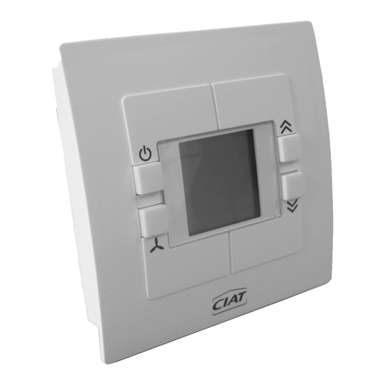
4 - USER TERMINAL AND RADIO-FREQUENCY TERMINAL Wall terminal with Flush-mounted terminal with digital display digital display Radio + receiver wall-mounted terminal 1) Display: This continuously displays the temperature detected by the sensor, the current operating mode, the chosen ventilation speed, and any alarm present. -
Page 8: Details Of The Display Terminal Screens
5 - DETAILS OF THE DISPLAY TERMINAL SCREENS : Comfort mode : Frost protection mode : Economy mode : Off mode : Heating in progress : Cooling in progress : Manual ventilation speeds : Alarm and fault : Automatic position : Setpoint shift bar chart 6 - MEANING OF SYMBOLS Heating... -
Page 9: Installation Parameters
Param. written on Parameter Name Explanation Setting range value slave This zone number allows a link to be created with the V300 Zone number 1...6 Zone timer Setpoint for heating control in comfort mode P04 + 0.5...P03-2.0 Heating comfort setpoint 19.0... - Page 10 Default Param. written on Parameter Name Explanation Setting range value slave Correction factor for sensor S1 - 9.9...+ 9.9 Sensor S1 calibration resolution of 0.1 Indoor environment Correction factor for the room sensor - 9.9...+ 9.9 sensor calibration resolution of 0.1 The auxiliary contact on input DI1 may be normally closed Action direction of or normally open:...
-
Page 11: Diagnostics
8 - DIAGNOSTICS To enter "Diagnostic" mode: - Press the keys simultaneously for 5 seconds → diagnostic d01 appears - Select the desired diagnostic using the keys - To consult a diagnostic: - To exit "Diagnostic" mode: Diagnostics Name Explanation Master/slave unit Number of slave controllers detected by the master (if the terminal is connected to a slave, number of slaves connected after this slave). -
Page 12: Wiring Schematic Diagram For Individual Units
Fused isolator Shunt (remove if Blue equipment connected) Brown Solenoid valve Connection terminal Speed selection as per ARC Equipment to be provided by the customer CIAT assembly optional Customer connection Shielded twisted pair Shared Customer connection if component supplied separately Green/Yellow... -
Page 13: Measuring The Temperature
10 - MEASURING THE TEMPERATURE The V300 offers the possibility of controlling the air temperature via a return sensor or a room sensor (P11). If you can choose between the two, it is preferable to opt for the indoor environment sensor, since it provides a better picture of the room temperature. -
Page 14: Characteristics Of The Sensors Used By The V300
- Changeover operation with water at neutral temperature: In this scenario, and if the controller requirement is confirmed, the V300 launches a test cycle on the valve so as to check the network's available water temperature (valve 100% opened to authorise water circulation in the terminal unit coil). -
Page 15: Radio-Frequency Terminal
If there is a bridge between these terminals, the controller deduces that the water is still hot. For P47 = 0, the controller waits for the water temperature value from the V300 zone timer in order to start heating or cooling (if it does not receive a value, it will automatically operate in "heating mode"... -
Page 16: Master/Slave Function
Press the button The display becomes "del" Deconfiguration is done automatically. The sequence is completed as soon as the display becomes "CF O". From this moment, the terminal and its receiver are unapplied In the case or "CF2" appears on the display(posting), it indicates that the désapairage of the terminal was made while the communication with his(her) receiver was broken. - Page 17 ; the keypad keys are locked. The slaves on the loop continue to operate in the last state indicated by the Master. The slaves remain controlled by the V300 Zone timer, if included. → If there is an alarm on one of the slaves: Only the slave concerned is powered off, the other units continue to operate as per the orders from the Master and its room terminal.
- Page 18 SLAVE MASTER SLAVE SLAVE SLAVE ..N SLAVE 1 TERMINAL TERMINAL TERMINAL POWER IN POWER IN POWER IN V300 V300 V300 230 V 230 V 230 V 230/1/50 POWER SUPPLY CONTROLLER/FAN MAX 15 SLAVES MASTER/SLAVE ARCHITECTURE NA 12.54 D EN - 16...
-
Page 19: Pi Control
16 - UNIVERSAL INPUTS The V300 controller is equipped with two configurable potential free inputs. These two inputs, D1 ┴ and D2- ┴ , are supplied from the factory with a bridge. If you want to connect contacts to the inputs (frame contact for example), the bridges must be removed. -
Page 20: Connecting The Frame Contact
17 - CONNECTING THE FRAME CONTACT Connecting the frame contact ● Parameter P16 or P17 Frame contact to be wired to input D1- ┴ or D2 ┴ depending on your device's configuration (refer to the corresponding wiring diagram). Regulator Window switch The cable used has a maximum length of 10 m, and minimum section of 0.9 mm². -
Page 21: Centralised Management With V300
Electrical cabinet Maximum: 30 offices (corresponding to Master and/or individual units) The comfort units (ductable, air handling units or cassettes), which are all independent, are equipped with V300 control. Each comfort unit has its own comfort temperature sensor. A centralised timer comprising a zone controller and a wired LCD terminal in an electrical cabinet outside the zone enable remote centralised management of this loop. -
Page 22: Electrical Connections - Cable Types
A summary of the types of bus cables used and their length The position of the zone clock in the building (if included) Note: when using the CIAT after-sales service, all of the above information will be requested by CIAT Services technicians before any work. -
Page 23: Terminal Dimensions
20 - TERMINAL DIMENSIONS Wired wall-mounted and radio-frequency version Colour RAL 9010 Controller wiring diagram Male faston terminals Quick-release connector Screws Screws 2.8 x 0.8 REF : 7335301 FAB : 1625/0001 LOG : V2.0 Made in France - 2016 Screws FAB: 1625 /0001 = Fabrication Year 2016/week no. -
Page 24: Using The User Terminals
0.315 Dimensions L x H x P (mm) 105 x 93 x 59 Additional information Assembly instructions NA 12.53A V300 Default configuration FO300 parameter sheet 21 - USING THE USER TERMINALS User procedure (for all systems): selector is used to select between Auto and Manual ventilation Selecting the mode on the terminal switches the controller to frost protection mode (depending on the configuration). - Page 26 CIAT Service www.ciat.fr This document is not legally binding. As part of its continuous drive to improve its equipment, CIAT reserves the right to make any technical modifications without prior notice. Registered address Avenue Jean Falconnier B.P. 14 01350 Culoz - France Tel.
Need help?
Do you have a question about the V300 and is the answer not in the manual?
Questions and answers