Table of Contents
Advertisement
Advertisement
Table of Contents

Related Manuals for CIAT FLOWAY


Summary of Contents for CIAT FLOWAY
- Page 1 NA 09.61 N 06 - 2016 C o n t r o l m a n u a l...
-
Page 3: Table Of Contents
CONTENTS Supervision and control The program The HMI terminal 1.2.1 Using the HMI terminal keys The room terminal (Option) 1.3.1 Controls 1.3.2 Displays 1.3.3 Room terminal information, settings and browsing 1.3.4 Electrical connections The controller Description of the air handling units Temperature regulation functional analysis Management of fire faults Managing night cooling... - Page 4 Communication menu 2.10 Alarms menu 2.11 Access level menu 2.12 Versions menu Managing a network of controllers pLAN electrical connections 3.1.1 Connecting controllers to the pLAN 3.1.2 Connecting a remote screen to the pLAN Addressing the pLAN Changing the controller address 3.3.1 Addressing the HMI terminals 3.3.2...
-
Page 5: Supervision And Control
Supervision and control The program This air handling unit is managed by its PLC. In addition to its control functions, it also monitors and detects any faults with the air handling unit. The HMI terminal displays the following data which can be edited at any time: Values of connected sensors Unit on/off cycles Calibration of the sensors... -
Page 6: Using The Hmi Terminal Keys
1.2.1 Using the HMI terminal keys Description Returns to the main Menu mask when pressed in any loop. The Menu loop displays the state of the unit. Provides access to the "Menu" Resets all setpoints, parameters and time delay values to their factory settings. The red button is used to display alarms and confirm acknowledgeable faults. -
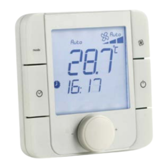
Page 7: The Room Terminal (Option)
The room terminal (Option) The terminal supplied is equipped with a digital display, 4 buttons and a rotary encoder. Once installed in the premises, the device can measure the ambient temperature and enables remote control of the air handling unit. 1.3.1 Controls Button not used... -
Page 8: Displays
1.3.2 Displays Unit operating mode Main display area Ventilation operating mode Ventilation operating speed Temperature unit Indicates whether the value displayed in the main area is a setpoint Indicates whether the value displayed in the main area is a humidity Area not used Day of the week 10. -
Page 9: Room Terminal Information, Settings And Browsing
1.3.3 Room terminal information, settings and browsing The diagram below shows the various browsing, information and setting options on the room terminal: Terminal energising A few seconds (2-3s) u1.3 Terminal initialising A few seconds (2-3s) Press Communication fault Unit on with the controller or Unit off (default... -
Page 10: Electrical Connections
1.3.4 Electrical connections Room terminal Controller J11 terminals The room terminal and the controller are electrically connected using an AWG20/22 shielded cable (not supplied) comprising two twisted pairs. The first and last controller must be no more than 500m apart. This network must never run parallel to power cables at a distance of less than 50 cm. -
Page 11: Description Of The Air Handling Units
5. NTC passive analogue inputs 6. 0-10 V analogue outputs 7. 24 V AC/V DC digital inputs 8. 230 V AC or 24 V AC/V DC digital inputs; 9. Not used 10. connector for all HMI terminals and for downloading the application program 11. -
Page 12: 1.10 Control Unit For Rotary Heat Exchanger
During operation with a constant supply air temperature, free cooling is inactive as the heating coils are still in use (except on the deadband). When operating in free cooling mode, the supply air temperature is not controlled. It is important to configure an outdoor temperature low limit (screen p17) which is sufficiently high to ensure no discomfort is caused. - Page 13 Connector J3 Supply air temperature sensor B4 The temperature of the air supplied to the room can be regulated based on the setpoint (if selected) 20 seconds after the fans are turned on. Common for B4 Fresh air (return air) temperature sensor B5 The fresh air temperature sensor protects the heat exchanger from the risk of frost by adjusting the stages of the electric pre-heater (depending on unit configuration), adjusting the bypass for the plate heat exchanger and indicating the fault (+ LED).
- Page 14 setpoint. This function is incompatible with air quality regulation. Pressure sensor B8 for supply air (return) filter fouling level The pressure sensor monitors the level of blockage in the filter. If the filter is clogged, the unit is shut off and the corresponding faults are displayed and the LED lights up. If the filter is dirty, the corresponding fault is displayed and the LED lights up, but the unit is not shut off.
-
Page 15: Other
Connector J16 Shared Mixing damper 3-point servomotor opening NO10 Mixing damper 3-point servomotor closing NO11 ---------- Shared Connector J17 NO12 Coil 1 pump control Shared NC12 ---------- Connector J18 NO13 Coil 2 pump control Shared NC13 ---------- Connector J19 ID15 ---------- ID16 ----------... -
Page 16: Reversal Depending On The Unit Type
Connector J10 6-channel connection for a standard user HMI Connector J11 Rx-/Tx- RS485 link for the pLAN network Rx+/Tx+ RS485 link for the pLAN network RS485 link for the pLAN network Connector J23 Not used 1.10.3 Reversal depending on the unit type Unit type CLASSIC RHE CLASSIC... -
Page 17: Access Level Selection Menu
Indicates fan operation "Prg" button Menu 14. Acce s s le ve ls 15.Ve rs ions ∼ 1. S e tpoints 2. Ma chine status 4. Machine parameters To switch to another menu, press the or buttons to scroll through the available menus. The selected menu is opposite the arrow and on a black background. -
Page 18: Supply Air T° Setpoint Calculation In "Precision" Mode
Supply air Upper limit 26.0°c Upper limit for calculated Supply air T° setpoint Lower limit 16.0°c Lower limit for calculated Supply air T° setpoint 2.2.1 Supply air T° setpoint calculation in "Precision" mode Fig.4 Calculated Supply air T° setpoint upper limit Setpoint °C lower limit... - Page 19 Cooling: Fig.8 Cooling requirement (%) °C Supply air temp. band neutral Cooling supply air setpoint Comfort: 16°C Eco: 18°C Level 2 access Air quality 0800ppm Air quality regulation setpoint Maximum flow rate 1000m3/h Maximum flow rate value of supply air fan for air quality control Comfort Indication of the operating mode for T°...
-
Page 20: Machine Parameters Menu
Level 2 access Pre-heating temperature 2.0°c Electric pre-heater stages starting-up temperature in the duct (-5 to 50.0°C) Morning heating 23.0°c Control setpoint in mode "Morning heating" mode (0 to 50.0°C) Frost protection 17.0°c Unit reactivation setpoint in "Standby" mode (0 to 50.0°C) Antifreeze prot. - Page 21 Maintenance Sensor B4 Maintenance Sensor B5 Maintenance Sensor B6 Maintenance Air quality sensor Maintenance Sensor B8 Maintenance Sensor B9 Maintenance Clock lithium battery Danger Internal hydraulic coil frost Danger Hydraulic coil in duct frost Maintenance Electric pre-heater Maintenance Electric heater Maintenance Hydraulic coil 1 pump Maintenance...
- Page 22 Configuration Level 3 access Type -------- Orientation ---- Type: Classic 1000. (plate heat exchanger) Classic 2000 (plate heat exchanger) Classic 3000 (plate heat exchanger) Classic 4000 (plate heat exchanger) Classic 5000 (plate heat exchanger) Classic 6000 (plate heat exchanger) Classic 1000 RHE (rotary heat exchanger) Classic 1500 RHE (rotary heat exchanger) Classic 2000 RHE (rotary heat exchanger) Classic 2500 RHE (rotary heat exchanger)
- Page 23 Supp. air filter coef. Return air filter coef. Supp. air filter coef.: Supply air filter coefficient as per selection table Return air filter coef.: Supply air filter coefficient as per selection table Selection table: Single filtration M5HEE F7HEE F9HEE Model Size min.
- Page 24 Coil 1 Coil 2 Electric heater Coil 1: Without: No coil Cold in duct: Cold water coil installed in Supply air duct Hot in duct: Hot water coil installed in Supply air duct Internal cold: Cold water coil built into air handling unit Internal hot: Hot water coil built into air handling unit Internal mixed: Cold or hot water coil (with Changeover thermostat) built into the air handling unit Mixed in duct: Cold or hot water coil (with Changeover thermostat) installed in the Supply air duct...
- Page 25 IR detector ---- th-Tune ---- Level 2 access Control priority IR detector: Without, With th-Tune: Without, With Control priority: Precision or Energy optimisation mode (Only available if Regulated T° (P4) = Ambient or Return air. If Regulated T° = Supply air, Control priority is forced to Precision) Configuration Level 3 access Humidifier...
-
Page 26: Adjustment Parameters Menu
Adjustment parameters menu Level 1 access Language ------------ Controller language selection (French, English, German, Spanish, Italian, Dutch) Setting Level 1 access of the clock Time -- :-- Clock time correction value Date --/--/-- Clock date correction value Supply air Level 2 access CLG band 0005.0 Proportional band for monitored temperature regulation in cooling mode... -
Page 27: Regulated T° Compensation Based On The Outdoor T
0-10V: Sensor physically wired to the controller com: Pressure value via the CMS Compensated Qv: Without, With (Fan flow rate compensation as per Fig. 2, page 25) Compensated T°: Without, With (Regulated temperature compensation as per Fig. 1, page 25) Free Cooling: Without, With Fire: Without, With Level 2 access... -
Page 28: Fan Flow Rate Compensation Based On Outdoor T
2.4.2 Fan flow rate compensation based on outdoor T° Level 2 access 030% E -20.0°c 100% F 10.0°c 030% K -20.0°c 100% L 10.0°c Comfort flow rate Fig.2 100% Outdoor T° 2.4.3 Duct pressure compensation based on the outdoor T° Nominal Fig. - Page 29 Fig. 3.bis Supply air flow rate Comfort Fault- tolerant Fresh air T° Screen appears if the "Morning heating" function is used in a time program (Level 2 access) Mixing opening in "Morning heating" mode 095% Opening value of mixing damper in "Morning heating" mode Screen appears if the "ECO recirculation"...
- Page 30 Fan output Sortie ventilateur Réglage temps de démarrage progressif p14 Soft start time adjustment p14 Visible at o1 in % Visible en o1 en % Increase of 10% output o1 every 10 secs Augmentation de 10% sortie o1 toutes les 10 s Start speed Vitesse start selected as p14...
- Page 31 Level 3 access FC offset -3.0°c Outdoor T° offset from regulated T° for Free Cooling authorisation Lower limit 15.0°c Outdoor temperature low limit in free cooling and night cooling mode Level 3 access Setpoint min. threshold Filter fouling level supply air ----Pa Supply air filter fouling minimum threshold (0-100 Pa) Setpoint min.
-
Page 32: Read-Only Parameters Menu
Calibration Level 3 access Dirty filter compensation Supply air ---Pa Supply air filter dirty detection threshold compensation Clogged filter compensation Supply air ---Pa Supply air filter clogged detection threshold compensation Calibration Level 2 access Dirty filter compensation Return air ---Pa Return air filter dirty detection threshold compensation Clogged filter compensation Return air ---Pa Return air filter clogged detection threshold compensation... -
Page 33: Outputs
Check Level 1 access Supply air fan Supply air fan operation check state (C = on; O = off) Return air fan Return air fan operation check state (C = on; O = off) Fire Fire detection sensor check state (F = no fire; O = fire detected) Rotary heat exchanger Rotary heat exchanger operation check state (F = on;... -
Page 34: Setpoints
Level 1 access Pump 1 State of hydraulic coil 1 pump control Pump 2 State of hydraulic coil 2 pump control Boiler or heat pump State of heat pump or boiler control (Heating or Cooling mode) Humidifier Humidifier operation authorisation state Screen visible for "Classic"... -
Page 35: Fault Memory Menu
Fault memory menu H000 Level 1 access Alarm 00 :00 00/00/00 H000 Indicates the log number for the alarm 00/00/00 Indicates the date of the alarm 00:00 Indicates the time of the alarm Alarm Indicates the alarm "Prg" button Level 3 access Reset Reset Reset the alarm log... - Page 36 The cursor places itself below the override authorisation (free or overridden). Confirm by pressing ENTER. The cursor places itself under the override value. Display the new value by pressing the button or the button. Confirm by pressing ENTER. The unit is now in "manual mode".
- Page 37 Fault relay Level 3 access free Danger….……………………. O Maintenance……………...….. O Bypass Level 3 access free opening.……………..……… O closing….……………..…… O State ………………….000.0% Electric heater Level 3 access free state 1…...…………..……… O state 2………………..…… O Mixing damper Level 3 access free opening.…………..……… O closing….…………..……...
-
Page 38: Time Prog Menu
Time prog menu Level 1 access → Day1 Day2 → Day3 → Day4 Period 00:00 → 00:00 Period 00:00 → 00:00 Period 00:00 → 00:00 Period 00:00 → 00:00 State: State: State: State: --------------------- --------------------- --------------------- --------------------- Period 00:00 → 00:00 Start and end times (hour and minute) of daily time program period State: Selection of the state during this period: ------... -
Page 39: Communication Menu
Period 00:00 → 00:00 Period 00:00 → 00:00 00:00 → 00:00 Period 00:00 → 00:00 Period State: State: State: State: --------------------- --------------------- --------------------- --------------------- Date 00/00/2000 Date 00/00/2000 Date 00/00/2000 Date 00/00/2000 Period 00:00 → 00:00 Start and end times (hour and minute) of annual time program period State: Selection of the state during this period: ------... -
Page 40: 2.10 Alarms Menu
pCO3 address Address of the controller on the pLAN communication network to the user terminal pLAN network state When the system starts up, the pLAN network may encounter a number of problems (card fault and terminal start-up) caused by incorrect connections or a wrong address. The state of the pLAN network can be displayed in real time on this special mask in order to identify which devices (controller or terminal) are correctly connected and addressed. -
Page 41: 2.12 Versions Menu
LEVEL 2 ACCESS Enter new code level 2? If yes, change the installer password; if no, back to current access level page Access levels LEVEL 2 ACCESS New password: 0000 Re-enter the new installer password Access levels If access level 2 selected and access level = 3 LEVEL 2 ACCESS Back to level 2: If yes back to access level 2... -
Page 42: Managing A Network Of Controllers
Managing a network of controllers The pLAN network (personal Local Area Network) is the name of the physical network that links controllers to remote HMI terminals. The connection of the controllers via the pLAN network allows the datapoints of one controller to be exchanged for another, following the logic set out by the program, i.e. -
Page 43: Addressing The Plan
Addressing the pLAN Once the controllers are connected over the pLAN network, the controllers and the terminals must be addressed. There is a range of 32 possible addresses (binary logic). As a result, a total of 32 controllers and terminals can be connected over the pLAN network. -
Page 44: Assigning Private And Shared Terminals
If the "setting" field is set to '0', the terminal will use the Point-to-Point Protocol (not the pLAN) to communicate with the controller and the "I/O board address: 07" field will disappear as it will not be necessary. 3.3.2 Assigning private and shared terminals Follow the procedure below if, at this point, it is necessary to change the list of terminals associated with each controller: •... -
Page 45: Replacing The Lithium Battery
Replacing the lithium battery The lithium battery must be replaced by the customer when the notification alarm appears, approximately 10 years after the unit is commissioned on site. Once the replacement has been carried out, do not forget to reset the battery check (screen tp1) Supervision The controller may be connected to a local or remote supervision PC or to most types of CMS (Modbus, Lonworks, KNX). -
Page 46: Modbus
Modbus 5.3.1 Modbus RTU connection diagram 5.3.2 RS485 connection close-up Description RX+/TX+ RX-/TX- The components required for connection to the remote and/or local ModBus supervision system are as follows: An asynchronous half duplex RS485 serial card in RTU mode, connected to each controller. A standard RS485/USB converter for connection to a PC (not supplied by the manufacturer). -
Page 47: Modbus Tcp Connection
11: Read event counter 15: Write n bits 16: Write multiple registers (16 bits) NB: The JBus addresses are equal to the "Modbus address" - 1 5.3.3 Modbus TCP connection The Modbus TCP protocol connection requires a communication card to be connected and configured as shown below. - Page 48 Click Configuration then pCO Com. In Protocol: Modbus Extended OR BACNET IP Baud rate: 19200 Then the button: Submit The speed (baud rate) must be identical in the communication menu EN-46...
-
Page 49: Variables
5.3.4 Variables 5.3.4.1 Controls Register Register decimal Description Format Type hex. no. Registers accessible in read-only mode (functions 1 or 2) for Booleans and write mode (functions 5 for char or 15) 0x118 Remote start/stop control (1 = On) Boolean Read-only/Write 0x119 Acknowledging faults (1 = Acknowledgement) -
Page 50: Reading Parameters
Register Register Adjustable decimal Description Format Type hex. no. values 0x1B4 Unit reactivation setpoint in "Standby" mode Integer Read-only/Write °C x10 0x1B9 Regulation setpoint in "Night cooling" mode Integer Read-only/Write °C x10 Supply air fan flow rate setpoint during a "Cool 0x1BB Integer Read-only/Write... - Page 51 Register Register decimal Description Format Type Values hex. no. 0 = Fault 0x463 1123 Electric pre-heater Boolean Read-only 1 = No fault 0 = Fault 0x464 1124 Electric heater Boolean Read-only 1 = No fault 0 = Fault 0x465 1125 Hydraulic coil 1 pump monitoring Boolean Read-only...
- Page 52 Register Register decimal Description Format Type Values hex. no. Calculated setpoint for heat exchanger frost 0x49F 1183 detection via return air pressure drop Integer Read-only measurement Calculated setpoint for detection of the 0x4A1 1185 Integer Read-only supply air "Filter dirty" level Calculated setpoint for detection of the 0x4A2 1186...
-
Page 53: Alarms
5.3.4.4 Alarms Register Register decimal Description Format Type hex. no. Registers accessible in read-only mode (functions 3 or 4) for integers Registers accessible in read-only mode (functions 1 or 2) for Booleans 0x514 1300 Danger fault summary Boolean 0 or 1 0x515 1301 Maintenance fault summary... -
Page 54: Lon
The communication card is supplied preloaded. The information data is retrieved via the CMS using a shunt on the Pin Service on the front panel of the expansion board. Connector for the controller Disconnectable terminal for connection of the LonWorks® network (GND, A, B) Pin service Green service LED: state of the node, lit during the pin service, flashing when the board... -
Page 55: The Analogue Datapoints
bit 3 Supply air filter dirty alarm bit 4 Heat exchanger frost alarm - Clogging detection bit 5 Heat exchanger frost alarm - Fresh air temperature check bit 6 Fire alarm bit 7 Return air motor alarm bit 8 Supply air motor alarm bit 9 Rotary heat exchanger alarm bit 10... -
Page 56: Description Of Knx Communication Card
The bus used is a TP1, with a transmission speed of 9600 Bds. This bus requires a special external power supply (supplied as an option) 5.5.1 Description of KNX communication card Meaning Cause / solution Constantly lit No communication between KNX Check the configuration: card and the controller - controller address incorrect... -
Page 57: Variables
5.5.2 Variables The KSet software is supplied for configuring the group addresses, as is the Carel_plugin_21.PR4 file for the ETS3 software (not supplied) and the CDFP2-V22.XML file from the database below: Description DatapointName Supply air filter fouling level FiltreIntroduction DPT_Value_Temp 9.001 9.001 Supply air duct pressure... - Page 58 Bit 2 = Sensor B3 Bit 3 = Sensor B4 Bit 4 = Sensor B5 Bit 5 = Sensor B6 Bit 6 = IAQ sensor Bit 7 = Sensor B8 Bit 8 = Sensor B9 Bit 9 = Hydraulic coil 1 pump Bit 10 = Hydraulic coil 2 pump Unit On/Off command via CMS OnoffGTC...
-
Page 59: The Plugin
The diagram below illustrates the phases of the "configuration process" required for configuring the card correctly: XML file kSET: XML file No group Enter the group complete addresses addresses ETS3 XML file ETS3 project ETS3 Assign the addresses Download XML file to Create the links to all the modules, the modules (table... - Page 60 . Select Import all . Using Files → "Open/Manage projects…", open the project named Carel_plugin_V2.1 (or above): . Open the project using Open, select the device "CAREL Plugin", right-click on the mouse and select Copy: Open or create the final project for the system and right-click on the mouse to paste the plugin, once or several times depending on the number of devices to be integrated.
-
Page 61: Assigning The Physical Address
5.5.5 Assigning the physical address The physical address of the KNX card is assigned using the standard procedure. You must ensure that: . the Bus wire network is drawn out and connected . the Bus is energised . the card is connected to the KNX network . - Page 62 Use "Choose XML file" to open the XML configuration file required. Click on "Download data" and wait for the "Success" message to be displayed. During this phase indicated by the "Performing operation" message and the LED on the card flashing green, no other operation may be performed. The download time may vary according to the size of the XML file and the network traffic;...
-
Page 63: Table Of Alarms
Table of alarms * All possible options are covered by this table Alarm Source Causes Solutions Supply air filter fouling - Filter too dirty - Replace filter pressure sensor Supply air filter 0-1000 Pa clogged Supply air filter - Filter fouled - Clean or replace filter dirty Fresh air temperature... -
Page 64: Control Curves
Control curves Filter and heat exchanger fouling check -3 Pa -3 Pa +3 Pa +3 Pa Filter dirty Filter blocked ∆P > "Filter dirty": Clogged filter, maintenance alarm ∆P > "Filter blocked": Filter blocked, system shut off alarm The Filter dirty and Filter blocked setpoints are calculated automatically (screen w4) by the controller according to the unit size and type, the type of filters and the instantaneous flow rates. - Page 65 CIAT Service www.ciat.fr Non-contractual document. With the thought of material improvement always in mind, CIAT reserves the right, without notice to proceed with any technical modification. Head office Avenue Jean Falconnier B.P. 14 01350 Culoz - France Tel. : +33 (0)4 79 42 42 42 Fax : +33 (0)4 79 42 42 10 info@ciat.fr - www.ciat.com...
Need help?
Do you have a question about the FLOWAY and is the answer not in the manual?
Questions and answers