Table of Contents
Advertisement
Quick Links
Advertisement
Table of Contents

Subscribe to Our Youtube Channel
Related Manuals for CIAT V300

Summary of Contents for CIAT V300
- Page 1 NA 14.13 A 01 - 2015 Control manual...
-
Page 3: Table Of Contents
1 CENTRALISED MANAGEMENT BY ZONE TIMER FOR COMFORT UNIT 1.1 Operating principle: 2 SCHEMATIC DIAGRAM 3 ZONE TIMER USER TERMINAL 4 DETAILS OF ZONE TIMER SCREEN 5 V300 ZONE TIMER PARAMETERS AND DIAGNOSTICS 6 PARAMETER TABLE 7 DIAGNOSTIC TABLE 8 OPERATING DATA 9 BUS WIRING/TOPOLOGY 9.1 Precautions:... -
Page 4: Centralised Management By Zone Timer For Comfort Unit
1 CENTRALISED MANAGEMENT BY ZONE TIMER FOR COMFORT UNIT The comfort units (ductable, air handling units or cassettes), which are all independent, are equipped with a V300 control. Each comfort unit has its own comfort temperature sensor. A centralised timer comprising a zone controller and a wired LCD terminal in an electrical cabinet outside the zone enable remote centralised management of this loop. -
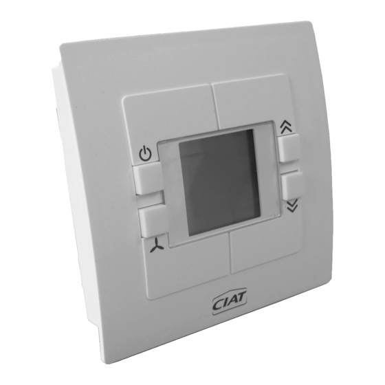
Page 5: Zone Timer User Terminal
(4) Contact inputs to override the installation in Comfort/Economy/Frost protection or Off mode (priority) (5) Authorising operation of the electric heaters on the comfort units (for bypass, etc.) (6) 230V output for automatic operation control (On/off) of ancillary equipment (AHU, extractors, etc.) (7) O utdoor temperature sensor option (activation limit for electric heaters on comfort units and/or advance heating restart). (8) RS485 communication bus: 2 shielded twisted pairs for connection → Terminal – Controller → Master and Slave controllers → Zone timer – Master or Individual controller 3 ZONE TIMER USER TERMINAL 1) Display: The permanent display shows: - The current time and day - The general state of the building (Auto or Override in progress) - The state of the central changeover (if option included) - The number of zones declared in the building 2) Navigation keys: These are used to enter settings (parameters, diagnostics, settings, etc.) 3) Validation key ... -
Page 6: V300 Zone Timer Parameters And Diagnostics
▪ Outdoor temperature sensor (depending on options) - To be wired to sensor S1- ┴ (terminal 31-32) - Enables: 1) activation limit for electric heaters on the comfort units 2) the installation to be started in advance for heating ▪ 230V – 10 A max. contact output slaved to a time schedule (auxiliary control): The 230V EH output is then considered as a separate zone and can be switched ON/OFF by the time schedule for this zone (e.g. start-up of auxiliary equipment: extractor, fan, etc.). This zone appears as "Zone 1 6" on the display. ▪ Display keys locked (securing access to operate the installation, etc.) 5 V300 ZONE TIMER PARAMETERS AND DIAGNOSTICS ▪ Two levels are available: - Level 1: settings - Level 2: system start-up Level 2 "System start-up" must be used with care: these settings configure the installation, therefore modifications must only be made with full knowledge of the situation. Ciat accepts no responsibility for operating malfunctions on the installation resulting from incorrect configuration ▪ Level 1 "Settings" access: - From the main screen - Press and hold the ... -
Page 7: Parameter Table
6 PARAMETER TABLE Access Setting Default Settings Name Explanation range value Setting Commissioning 0.0...9.0 resolution Comfort setpoint setting range Rules for maximum +/- shift of the setpoint for room units defined by No comfort setpoint Defines the display resolution for the comfort setpoint 0.5 : 1.0 adjustment shift on the room units... - Page 8 Access Setting Default Settings Name Explanation range value Setting Commissioning Length of the override when the user selects a mode higher than the zone timer mode. May be set to remain on at all times, to turn on for a specific period, or be disabled.
-
Page 9: Diagnostic Table
A) Zone controller/Zone terminal - RS 485 bus, 4 wires + shielding - Polarity to be observed (with denomination A = + and B= -) on the same twisted pair - Shielding to be fitted along the entire length and connected at the controller and terminal end (via ┴ terminals) - Maximum distance = 30 m - F ilotex FMA-2P type bus cable, Belden 2 pairs ref. 9842/9842NH 24AWG or equivalent (2 shielded twisted pairs) - See diagram 7415353 With changeover sensor BOILER ROOM MECHANICAL ROOM To V300 SELF- CONTAINED UNIT V300 POWER IN V300 230 V 230/1/50 CONTROLLER POWER SUPPLY EN - 7 N 14.13 A... - Page 10 B) Zone controller to "Individual" or "Master" controllers - RS 485 bus, 2 wires + shielding - Polarity to be observed (with denomination A = + and B= -) on the same twisted pair - Shielding continuity to be ensured along the entire length (via ┴ terminals of the controllers) - Max. total length of the bus: 200 m (see below) - Number of Master or Individual V300 controllers: 30 max. - Filotex FMA-2P type bus cable, Belden 2 pairs ref. 9842/9842NH 24AWG or equivalent (2 shielded pairs) - Topology: • Zone timer must be placed at the head of bus • Ideal: Serial bus/total bus length = 200 m max. or • A cceptable: Main dorsal L = 200 m max. with max. 5m long branch to connect each master or individual unit. • Star or loop prohibited - Junction box for branches • The cable connection to the junction connector (per pair) must match the polarity • The shielding must have continuity in the junction box • It is prohibited to use boxes carrying 230V or strong current • See schematic diagram on p10...
- Page 11 2/ Declare the number of zones on the timer: see below 3/ Check the d08 on each Comfort unit (d08 = 1 communication OK: used to check that all the units are correctly connected to the zone timer and that they are receiving the settings entered. 4/ Set the general timer: Hours - minutes - day of the week: see p20 (§ 4 Setting the Timer) 5/ Set the time slots for each zone if necessary: see below and p15 (§ 1 Time Setting) Declaring the zones (6 maximum) A) On each V300 controller for the Master or Individual comfort units: - Set the P01 "Zone number" corresponding to the desired zone (manual N12-53) - All the units on which P01 = 1 will be assigned to zone 1, etc. B) On the zone timer: - Set the corresponding P66 "Number of zones" (see "System start-up" level/default: 6 zones) - P 67 allows an additional zone, called zone "1-6" to be declared for the on/off automatic operation control of auxiliary equipment...
-
Page 12: General Tree Structure For The Different Menus
Time schedule - A default time schedule exists for each zone created in the timer (valid for the x zones declared) - This time schedule corresponds to classic "Office" use → "Comfort" mode from 07:00 to 18:00 over the first 5 days of the week → "Economy" mode from 18:00 to 07:00 → "Frost protection" mode at the weekend from 18:00 to 07:00 (corresponding to the last 2 days). Monday to Friday Days 1 to 5 7 : 00 Comfort Monday to Thursday Days 1 to 4 18 : 00 Economy Friday... -
Page 13: Main Menus
▪ O n the main screen, the MENU key is used to successively select and view the state of all zones, each declared zone, then zone 1 6 if it has been declared (the ZONE indicator flashes). The MENU key can then be used to access the "set timer" menu, before returning to the main screen. ▪ T he key is used to enter the selected zone sub-menu. The MENU key is used to navigate within this sub-menu, and to return to the zone's main screen. If none of these menus is confirmed using the key within 10 seconds, the display automatically returns to the main screen. ▪ I t is also possible to access the parameter and diagnostic menus from the main screen, in the same way as on a V300 room terminal. 11 MAIN MENUS → From the main screen: Access by successively pressing the "MENU" key → 4 main menus: Main screen/All Zones/Zone 1, Zone 2, Zone x…/ Zone1-6 (if present) / Set Timer scroll successively. → The general Building override is performed in the "All Zones" screen → T he Override/Time schedule/Setpoints sub-menus are accessible from the following menus: All zones (general building... - Page 14 "Zone 1 6" screen ZONE 1-6 (if present) • This zone corresponds to the presence of auxiliary equipment • "Zone" flashes/the selected Zone 1 6 is displayed "Set timer" screen Set timer • Press the MENU key • Hours, minutes and day of the week flash → If none of these menus is confirmed, the main screen will automatically be displayed after 10 seconds → The Menu key is used to return to the main screen EN - 12 N 14.13 A...
-
Page 15: Settings
11.2 Settings: 1) "All Zones" general setting (Building) → From this level, all the declared zones will adopt the time, override and setpoint settings; the settings entered at zone level will be overridden " All zones" screen • From the "All Zones" screen (via Menu) • : Used to enter the General All Zones menu → Used to directly access the "Override" menu → The logos for the different modes flash • MENU : used to scroll through the menus → Time Schedule All Zones → All Zones setpoints • : Used to enter the selected sub-menu "Override" screen All Zones override (or Building) • the logos for the different modes flash • All zones lit steady = setting valid for All zones • : used to enter the Override sub-menu •... - Page 16 • 3 different time slots • Corresponding to classic "Office" type occupancy → Default: There is no time slot set for the general Building time: • At initial start-up, the time slot display at this level is: This allows: • Each zone to be individually and independently modified if necessary • M odification/creation of a time slot at Building level will override any time slots set for any of the zones As a precaution, the MENU key can be used to cancel the modification in progress and exit the time slot modification sequence → The time slots are organised in ascending time order (day not taken into account) → The MENU key is used: → To add a time slot: • Press and hold MENU to insert an empty slot • It can be entered in any order • It will be automatically reorganised in ascending time order → D uring setting, briefly pressing MENU cancels the current setting and returns to the display of the selected time slot → To cancel a previously saved time slot: for more than 2 seconds → The default time schedule display is as follows: • Three different slots corresponding to: • Start-up at 07:00 in Comfort mode over 5 days (Monday to Friday morning) • Stop at 18:00 in Economy mode over 4 days (Monday to Thursday evening) • Stop at 18:00 in Frost protection mode on Friday evening...
- Page 17 • Scrolling through time slots using the keys, for viewing onl y • From a flashing display of a time slot: → The key is used to enter and modify the time slot, if necessary • Table for defining your new time slot: Used to define your requirement before programming as desired: Zone no.: _______ Day of the week Corresponding Days Times Operating mode concerned □□□□□□□ □ □ □ □ □□□□□□□ □ □ □ □ □□□□□□□ □ □ □ □...
- Page 18 → The new time schedule is now displayed as follows: • Five different slots corresponding to: New slot New slot End of time slot 12:00 14:00 → A time slot can be deleted as follows: • Go to the time slot to be deleted • for two seconds • The display now shows: " -- : -- " (either briefly with display of the next time slot or permanent if end of time slot) • The slot is deleted • MENU to exit "All zones"...
- Page 19 2) Zones x menus: This menu allows individual adjustment of each Zone for: → Its time slot → Its manual override → Its setpoints If settings have previously been entered at the "All Zones" level, they will be overridden for this zone → T he operations for entering these settings are identical to the "All Zones" menu (see above) for the previously selected zone Main screen with Zone 1 overridden • Example of a main screen in which Zone 1 has been overridden • "1" flashes to indicate that an override is in progress for this zone + logo • A UTO is still present: the other zones are still on the time schedule Zones 1 6 menu: (if present) This menu allows individual adjustment of this zone, which is dedicated to controlling auxiliary equipment as follows: → On – Off as per a time schedule with: On = and Off = → On-Off manual override → Consequently, only the two Override and Time Schedule sub-menus exist for this zone → Setting identical to the other zones Setting the timer: "Set timer"...
-
Page 20: Zone Timer Controller & Terminal Dimensions
12 ZONE TIMER CONTROLLER & TERMINAL DIMENSIONS Controller: Detachable screw terminals Location for configuration label (affixed by CIAT) Mounting on sym. rail width 35 - depth 7.5 Identification label Comprising: - CIAT item code - Production batch/Serial no. - Software version number Marking details: V300 REF : 7335309 FAB : 1425/0002 LOG : V1.06... -
Page 21: Technical Specifications
Wall-mounted terminal: 13 TECHNICAL SPECIFICATIONS Operating voltage 230V+N/50-60Hz Operating consumption 2.5 W Standby consumption 1.3 W min. Safety Low Voltage (SELV) (Safety Data output Extra Low Voltage) Connection type Screw terminal block Authorised ambient temperature 0°C...+45°C Protection class II as per EN 60 730-1 in case of correct installation Degree of protection IP 20 as per EN60529 Power reserve (powered off) 12 H Pollution degree Rated impulse withstand voltage... - Page 24 Tel.: 08 11 65 98 98 - Fax: 08 26 10 13 63 (€0.15/min.) This document is not legally binding. As part of its continuous drive to improve its equipment, CIAT reserves the right to make any technical modifications without prior notice. Registered address Avenue Jean Falconnier B.P.
Need help?
Do you have a question about the V300 and is the answer not in the manual?
Questions and answers