Pilz PNOZ s30 Operating Manual
Safety relays
Hide thumbs
Also See for PNOZ s30:
- Operating manual (99 pages) ,
- Operating manual (95 pages) ,
- Operating manual (134 pages)
Table of Contents
Advertisement
Advertisement
Table of Contents

Related Manuals for Pilz PNOZ s30


Summary of Contents for Pilz PNOZ s30
- Page 1 PNOZ s30 Safety relays Operating Manual-1001715-EN-13...
- Page 2 Preface This document is the original document. All rights to this documentation are reserved by Pilz GmbH & Co. KG. Copies may be made for internal purposes. Suggestions and comments for improving this documentation will be gratefully received. Pilz®, PIT®, PMI®, PNOZ®, Primo®, PSEN®, PSS®, PVIS®, SafetyBUS p®, SafetyEYE®, SafetyNET p®, the spirit of safety®...
-
Page 3: Table Of Contents
Section 6 Commissioning Wiring 6.1.1 General wiring guidelines 6.1.2 Pin assignment of RJ45 socket 6.1.3 Supply voltage 6.1.4 Connection of proximity switches 6.1.5 Connection of a rotary encoder 6.1.5.1 Connect rotary encoder to speed monitor Operating Manual PNOZ s30 1001715-EN-13... - Page 4 Technical details Safety characteristic data Section 9 Supplementary data Service life graph of output relays Categories 9.2.1 Safety level 9.2.2 Safety functions 9.2.3 Safety-related characteristic data for operation with non-safety-related ro- tary encoder without additional requirements Operating Manual PNOZ s30 1001715-EN-13...
- Page 5 9.2.9.2 Safety-related architecture 9.2.9.3 Achievable safety level Examples 9.3.1 Connection of proximity switch 9.3.1.1 Features 9.3.1.2 Configuration overview 9.3.1.3 Connection 9.3.2 Incremental encoder connection 9.3.2.1 Features 9.3.2.2 Configuration overview 9.3.2.3 Connection Section 10 Order reference Operating Manual PNOZ s30 1001715-EN-13...
-
Page 6: Introduction
Introduction Introduction Validity of documentation This documentation is valid for speed monitors PNOZ s30 from version 2.2. It is valid until new documentation is published. This operating manual explains the function and operation, describes the installation and provides guidelines on how to connect the product. - Page 7 Introduction Information This gives advice on applications and provides information on special fea- tures. Operating Manual PNOZ s30 1001715-EN-13...
-
Page 8: Overview
Chip card Chip card holder Documentation on data medium 2.1.2 Unit features Using the product PNOZ s30: Speed monitor for safe monitoring of standstill, speed, speed range, position and direction. The product has the following features: Measured value recorded by –... -
Page 9: Front/Side View
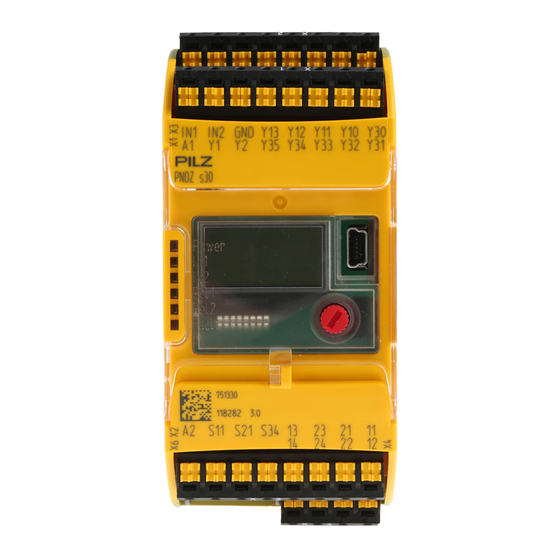
Relay outputs (auxiliary contacts) Y32 ... Y35: Semiconductor outputs (auxiliary outputs) S11: +24 V / 30 mA (supply for S34, Y1 and Y2) S21: 0 V (GND for S11, S34, Y1 and Y2) S34: Reset input Operating Manual PNOZ s30 1001715-EN-13... - Page 10 1: Chip card 2: Display 3: USB connection (service only) 4: Rotary knob 5: Expansion interface for 2 more external relay outputs LEDs: – Power – – – Rel 1 – Rel 2 – Fault Operating Manual PNOZ s30 1001715-EN-13...
-
Page 11: Safety
Damage can be attributed to not having followed the guidelines in the manual Operating personnel are not suitably qualified Any type of modification has been made (e.g. exchanging components on the PCB boards, soldering work etc.). Operating Manual PNOZ s30 1001715-EN-13... -
Page 12: Disposal
The guarantee is rendered invalid if the housing is opened or unauthorised modifica- tions are carried out. Sufficient fuse protection must be provided on all output contacts with capacitive and in- ductive loads. Operating Manual PNOZ s30 1001715-EN-13... -
Page 13: Function Description
Introduction Proximity switches or rotary encoders record measured values, which are evaluated in the speed monitor PNOZ s30. There are 9 monitoring functions (F1 ... F9), which are per- formed simultaneously. Up to 16 different parameter sets (P0 ... P15) for the monitoring functions can be selected via the select inputs. -
Page 14: Functions
The individual blocks are galvanically isolated from each other: If possible, the connections for the various earth potentials (GND, S21, Y30 und A2) should not be connected on the PNOZ s30 but should be connect- ed directly to the GNDs on the connected units, otherwise noise susceptibili- ty may be increased significantly (conductor loops are not permitted). - Page 15 (configured window width) and the assigned output is switched on. The output will stay switched on provided the current position is within the position window. Operating Manual PNOZ s30 1001715-EN-13...
- Page 16 For both directions, a tolerance can be entered for the wrong direction. In other words, the drive can run in the wrong direction up to the set tolerance value, without the assigned out- put switching off. Operating Manual PNOZ s30 1001715-EN-13...
- Page 17 Direction monitoring is always active, irrespective of whether it is used in the selected parameter set. Direct.Right and Direct.Left are active when the PNOZ s30 is started up. Direction cannot be detected if proximity switches are used. Timing diagram for direction monitoring:...
- Page 18 Units The values to be configured can be entered in various units. Depending on the axis type (linear or rotational axis), various units can be selected for speed and distance (see chapter entitled "Menu overview"). Operating Manual PNOZ s30 1001715-EN-13...
-
Page 19: Timing Diagram For Speed Monitoring
Up to 16 parameter sets (P0 ... P15), each with a max. of 9 switch functions (F1 ... F9) can be configured to monitor various operating modes, for example. One of the 16 parameter sets is selected via 4 select inputs SEL1 (Y10), SEL2 (Y11), SEL4 (Y12), SEL8 (Y13). Operating Manual PNOZ s30 1001715-EN-13... - Page 20 F1: Standstill 2 Hz F2: Overspeed: 3000 Hz F3: Warning threshold: 2800 Hz The following outputs are assigned to the switch functions: F1: Relay output Rel. 1 F2: Relay output Rel. 2 F3: Semiconductor output Out 1 Operating Manual PNOZ s30 1001715-EN-13...
-
Page 21: Select Inputs
"1 from 4" mode For applications up to PL e of EN ISO 13849-1 and SIL CL 3 of EN IEC 62061. A maximum of 4 parameter sets can be configured and used: P1, P2, P4 and P8. Operating Manual PNOZ s30 1001715-EN-13... - Page 22 PL d of EN ISO 13849-1 and up to SIL CL 2 of EN IEC 62061. Parameter set Signal states of the select inputs SEL 8 (Y13) SEL 4 (Y12) SEL 2 (Y11) SEL 1 (Y10) Operating Manual PNOZ s30 1001715-EN-13...
-
Page 23: Switch Functions
For both directions, a tolerance can be entered for the wrong direction. 4.4.3 Basic configuration Two basic configurations are available for standard applications, for simple configuration within the display menu. A basic configuration contains limited menu functions adapted for standard applications, with partly pre-defined parameters. Operating Manual PNOZ s30 1001715-EN-13... - Page 24 – Speed (F2) – Max. frequency (v max) configurable in Hz – Direction (F3) Direction left Tolerance for wrong direction = 10 Imp – Direction (F4) Direction right Tolerance for wrong direction = 10 Imp Operating Manual PNOZ s30 1001715-EN-13...
-
Page 25: Chip Card
The cable used to connect the proximity switches must be shielded (see connection di- agrams in the chapter entitled "EMC-compliant wiring"). The supply voltage of the proximity switches should be monitored via track S. Operating Manual PNOZ s30 1001715-EN-13... -
Page 26: Rotary Encoders
Track S can be used: – To connect an encoder's error output – To monitor voltages between 0 V and 30 V for a permitted upper and lower limit. For example, the encoder's supply voltage can be monitored. Operating Manual PNOZ s30 1001715-EN-13... -
Page 27: Output Signals
AB" -> "Track AB fmax" / "Track Z" -> "Track Z fmax"). – The ratio fAB/fZ ("Encoder Settings" menu -> "Track Z" -> fAB/fZ Verh.) Please note the values stated in the technical details 4.5.2.1 Output signals Output signals TTL, HTL Single ended Differential (/Z) Operating Manual PNOZ s30 1001715-EN-13... -
Page 28: Adapter For Incremental Encoders
The adapter records the data between the incremental encoder and the drive and makes it available to the speed monitor via the RJ45 socket. Pilz supplies complete adapters as well as ready-made cable with RJ45 connector, which can be used when making your own adapter. The range of products in this area is constant- ly being expanded. -
Page 29: Installation
Electrostatic discharge can damage components. Ensure against discharge before touching the product, e.g. by touching an earthed, conductive surface or by wearing an earthed armband. 5.1.1 Dimensions *with spring-loaded terminals 98 (3.86") * 100 (3,94") (1.77") Operating Manual PNOZ s30 1001715-EN-13... -
Page 30: Commissioning
If possible, the connections for the various earth potentials (GND, S21, Y30 und A2) should not be connected on the PNOZ s30 but should be connected directly to the GNDs on the connected units, otherwise noise susceptibility may be increased signifi- cantly (conductor loops are not permitted). -
Page 31: Connection Of Proximity Switches
24 V INI_A RJ45 INI_B pnp proximity switch with resistor R = 10 kOhm npn proximity switch with resistor R = 47 kOhm Operating Manual PNOZ s30 1001715-EN-13... -
Page 32: Connection Of A Rotary Encoder
Connect rotary encoder to speed monitor Encoder types: TTL single ended HTL single ended Please note: Tracks/A, /B, Z, and /Z must remain free Input Device PNOZ s30 Encoder types: TTL differential HTL differential sin/cos 1 Vss Hiperface Operating Manual PNOZ s30 1001715-EN-13... -
Page 33: Connect Rotary Encoder With Z Index To Speed Monitor
Connect rotary encoder to the speed monitor via an adapter The adapter (e.g. PNOZ msi6p) is connected between the rotary encoder and the drive. The output on the adapter is connected to the RJ45 socket on the speed monitor. Operating Manual PNOZ s30 1001715-EN-13... -
Page 34: Connection Of Proximity Switch And Rotary Encoder
TTL single ended (A,B) + HTL differential (A as Z) – TTL single ended (A,B) + HTL single ended (A as Z) Please note: Tracks /A, /B and /Z must remain free. Input Device PNOZ s30 24 V Operating Manual PNOZ s30 1001715-EN-13... -
Page 35: Reset Circuit
Hiperface (A,/A,B,/B) + HTL single ended (A as Z) Please note: Track /Z must remain free!! Input Device PNOZ s30 24 V 6.1.7 Reset circuit Automatic reset Monitored reset Automatic reset must only be configured No wiring necessary! Operating Manual PNOZ s30 1001715-EN-13... -
Page 36: Feedback Circuit
Select inputs 6.1.10 Semiconductor outputs EMC-compliant wiring 6.1.11 EMC-compliant wiring for connecting a rotary encoder Cabinet Shielded Connection Box Input Device PNOZ s30 24 V DC Power Supply 0 V DC 24 V DC PE Operating Manual PNOZ s30 1001715-EN-13... - Page 37 A or B or C or D or E Conductor loops outside the shield must be avoided. If a shielded junction box is not used, the shield must run continuously from the encoder to the evaluation device. Operating Manual PNOZ s30 1001715-EN-13...
-
Page 38: Display Menu - Configuration
The menu settings are made on the unit's display via a rotary knob. You have the option to make the settings on the knob by hand or with a screwdriver. If you make the settings with a screwdriver, the knob can remain within the unit. Operating Manual PNOZ s30 1001715-EN-13... -
Page 39: Create Configuration Overview
– Press the latch on the side of the rotary knob (1) towards the centre of the knob. This releases the rotary knob. – Press the knob downwards (2) while keeping the latch held down. Operating Manual PNOZ s30 1001715-EN-13... -
Page 40: Configure Speed Monitor
The configuration is protected through passwords. There is a master password and a cus- tomer password. Factory setting for both passwords: 0000 The password levels contain different authorisations: Master password Display: All settings Edit: All settings Operating Manual PNOZ s30 1001715-EN-13... -
Page 41: Use Chip Card
Unit parameters are automatically saved to the chip card during operation. As a result, the chip card always contains a copy of the unit's current internal data. Exception: If you select Write configuration to SIM: No. Operating Manual PNOZ s30 1001715-EN-13... -
Page 42: Insert Chip Card
Make sure that you do not bend the chip card as you insert it into the chip card slot. 6.2.5.2 Write data to chip card If you are inserting a chip card which has not yet been written by a PNOZ s30, you have the option to: Insert... -
Page 43: Read Data From Chip Card
Commissioning 6.2.5.3 Read data from chip card If you are inserting a chip card which has not yet been written by a PNOZ s30, you have the option to: Insert chip card (data Data is read into on chip card different... -
Page 44: Menu Overview
Rel.2 Out 2 Default: 500 Hz Other, pre-defined settings: Encoder type 2 pnp type proximity switches Parameter set/select input P0, select inputs are ignored (Select inputs mode: "None") Hysteresis Standstill and speed, 2 % each Operating Manual PNOZ s30 1001715-EN-13... -
Page 45: Basic Settings For The Rotary Encoder
-Hiperface (A, /A, B, /B) Standstill Enter standstill frequency 10 mHz to 1.00 kHz Rel.1 Out 1 Default: 100 Hz v max: Enter the max. permitted speed 10 mHz to 1.00 MHz Rel.2 Out 2 Default: 5.00 kHz Operating Manual PNOZ s30 1001715-EN-13... - Page 46 Direction left: External output Ext. 1 and semiconductor output Out 3 – Direction right: External output Ext. 2 and semiconductor output Out 4 Reset mode – All outputs: Automatic reset Switch delay None Max. encoder frequency 1 MHz Operating Manual PNOZ s30 1001715-EN-13...
-
Page 47: Settings
1 m = x Imp (x = 1 ... 10.000.000 Imp) 1 rot = x Imp (x = 1 ... 10.000.000 Imp) Encoder Create encoder configuration for the tracks A, Settings /A, B, /B, Z, /Z, S Operating Manual PNOZ s30 1001715-EN-13... - Page 48 Sin/Cos 1 Vss - sin/cos 1 Vss (A, /A, B, /B) Sin/Cos 1 Vss with Z index - sin/cos 1 Vss Z Index (A, /A, B, /B, Z, Hiperface - Hiperface (A, /A, B, /B) Operating Manual PNOZ s30 1001715-EN-13...
- Page 49 Select direction for tracks A and B - Normal Information: Default: - Inverted This function is used to display a Normal forward movement as positive line- ar/rotational speed, irrespective of the installation of the rotary encod- Operating Manual PNOZ s30 1001715-EN-13...
- Page 50 Track S Settings for track S (error track) Track S Use of track S: - Not used Default: - Not used (track S is not used) - Evaluation Not used - Evaluation (track S is used) Operating Manual PNOZ s30 1001715-EN-13...
- Page 51 "Standstill v max:" (see above) (F1 ... F9) (P0 … Select linear/rotational speed limit 10 mHz ... 1.00 MHz P15) or the corresponding value in the select- v max ed unit 2,00 kHz Operating Manual PNOZ s30 1001715-EN-13...
- Page 52 - Automatic separately (Rel.1... Out 4) - Monitored / Automatic: Automatic start Default: - Monitored \ Monitored /: Monitored start with Monitored / rising edge at S34 Monitored \: Monitored start with falling edge at S34 Operating Manual PNOZ s30 1001715-EN-13...
-
Page 53: Advanced Settings
Setting for the delay effect and de- lay time for the outputs Delay Delay Setting for the delay time effect and delay time for the respective Output output (Rel.1 ... Out 4) Default: On 0 ms (display only) Operating Manual PNOZ s30 1001715-EN-13... - Page 54 Select whether the parameters are - ESCAPE to be reset to the default settings Settings - YES YES: All parameters are reset to the default values. The language is set to English and all passwords are set to 0000. Operating Manual PNOZ s30 1001715-EN-13...
-
Page 55: Information
2.+3. Line: Plain text to describe error (can be rectified by user) for the user System errors: Level 2 and 3 Level 3: (internal error, information for Pilz 1. Line: Seq. No. "repairable" Service). 2. Line: "System time:" See section entitled "Error stack 3. - Page 56 1. Line: Seq. No. "Err.:", error number System errors: Level 2 and 3 2.+3. Line: Plain text to describe error for the user (internal error, information for Pilz Service). Level 3: The error messages can be hidden 1. Line: Seq. No. "Repairable"...
- Page 57 -> Select whether the data on the chip card is to be saved. Password messages Master PW -> Enter master password 0000 ... 9999 required: Default: 0000 Password required: -> Enter customer password 0000 ... 9999 Default: 0000 Operating Manual PNOZ s30 1001715-EN-13...
-
Page 58: Example: Configure Basic Configuration 2
>Standstill Rel.1 Out 1 Rel.1 Out 1 300 Hz 300 Hz save? Standstill max: F1 S0 Rel.1 Out 1 300 Hz 300 Hz save? v max: Rel.2 Out 2 5,00 kHz Basic Settings Enc. ESCAPE Operating Manual PNOZ s30 1001715-EN-13... -
Page 59: Operation
Error on relay output 1 Relay output 2 is switched on Error on relay output 2 Fault that can be repaired by the user leading to safe condition. Internal error leading to a safe condition. Operating Manual PNOZ s30 1001715-EN-13... -
Page 60: Display
Remedy: Rectify error; if necessary, contact Pilz – Internal errors (system errors, all errors that are not described in the list) Remedy: Switch device on and off, contact Pilz 7.1.2.2 Current error messages If an error is detected, the "Fault" LED lights up on the device and an error message ap- pears on the display (see error stack). - Page 61 A and B a falling edge at input S34 (Start) e.g. due to edge jitter at standstill over an - Ensure that the proximity extended period switches operate correctly Operating Manual PNOZ s30 1001715-EN-13...
- Page 62 -Ensure that the wiring is correct 10247 Signal Offset The signal at track B -Ensure that the encoders are has a DC offset configured correctly Track B -Ensure that the encoder oper- ates correctly -Ensure that the wiring is correct Operating Manual PNOZ s30 1001715-EN-13...
- Page 63 10255 Signal on The inverted tracks -Ensure that the encoders are carry a voltage signal configured correctly inverted track Target status: no sig- -Ensure that the wiring is correct nal (not connected) Operating Manual PNOZ s30 1001715-EN-13...
- Page 64 -Ensure that the encoders are configured correctly -Ensure that the proximity switches operate correctly -Ensure that the supply voltage is present at the proximity switches Ensure that the proximity switch- es are wired correctly Operating Manual PNOZ s30 1001715-EN-13...
- Page 65 Signal error No feasible signal at -Ensure that the encoders are the tracks /A/B configured correctly Track /A or /B -Ensure that the encoder oper- ates correctly -Ensure that the wiring is correct -Check supply voltage. Operating Manual PNOZ s30 1001715-EN-13...
-
Page 66: Open Circuit Message
- Check whether a proximity switch cy of the proximity constantly switches due to the switch at track B for too drive's edge jitter. long and by too much. Operating Manual PNOZ s30 1001715-EN-13... -
Page 67: Technical Details
0 - 1.000 kHz Configurable monitoring frequency Without hysteresis 10 mHz - 1.000 kHz 10 mHz - 1.000 kHz Incremental encoder input 750330 751330 Number of inputs Connection type RJ45 female connector, 8-pin RJ45 female connector, 8-pin Operating Manual PNOZ s30 1001715-EN-13... - Page 68 4,0 A 4,0 A Safety contacts, AC15 at 230 V 230 V Max. current 3,0 A 3,0 A Safety contacts, DC13 (6 cycles/ 24 V 24 V min) at Max. current 4,0 A 4,0 A Operating Manual PNOZ s30 1001715-EN-13...
- Page 69 30 ms 30 ms Min. start pulse duration with a monitored reset With rising edge 30 ms 30 ms With falling edge 30 ms 30 ms Supply interruption before de-ener- 20 ms 20 ms gisation Operating Manual PNOZ s30 1001715-EN-13...
- Page 70 0,20 - 1,50 mm², 24 - 16 AWG – tion, flexible without crimp con- nectors or with TWIN crimp con- nectors Torque setting with screw terminals 0,50 Nm – Connection type Screw terminal Spring-loaded terminal Mounting type plug in plug in Operating Manual PNOZ s30 1001715-EN-13...
-
Page 71: Safety Characteristic Data
PFH value can be used irrespective of the switching frequency and the load, as the PFH value already considers the relay's B10d val- ue as well as the failure rates of the other components. Operating Manual PNOZ s30 1001715-EN-13... -
Page 72: Supplementary Data
With capacitive loads, any power surges that occur must be noted. With contac- tors, use freewheel diodes for spark suppression. Categories 9.2.1 Safety level The maximum achievable safety level depends on the encoder, the wiring and the operat- ing mode of the PNOZ s30. Operating Manual PNOZ s30 1001715-EN-13... -
Page 73: Safety Functions
Position Speed Speed range Direction Monitoring for broken shearpins The safety functions of the PNOZ s30 are monitoring functions, whereby a safe output sig- nal is used to show if defined limit values are exceeded. Operating Manual PNOZ s30 1001715-EN-13... -
Page 74: Permitted Encoder Types And Output Signals
PNOZ s30. The monitoring function of the PNOZ s30 can be used to implement safety functions de- fined in the standard EN 61800-5-2 for Adjustable speed electrical power drive systems. -
Page 75: Safety-Related Architecture
The two signal tracks must not be generated by a common processor One signal may not be derived from the other signal via an electronic circuit. 9.2.4.2 Safety-related architecture SRP/CS SRP/CS SRP/CS Sensor Logic Actuator Sensor PNOZ s30 Actuator non-safe encoder Logic Diagnostic Operating Manual PNOZ s30 1001715-EN-13... -
Page 76: Achievable Safety Level
Supplementary data To calculate the safety function you will need the following data for the "sensor" subsystem and "PNOZ s30" subsystem: Sensor PNOZ s30 subsystem Category MTTFd Operating mode PFH (1/h) Manufactur- 90 % Monitoring 2,34E-08 er-specific 1 encoder 9.2.4.3... -
Page 77: Safety-Related Architecture
PNOZ s30 Actuator non-safe encoder Logic Diagnostic Drive Control Diagnostic To calculate the safety function you will need the following data for the "sensor" subsystem and "PNOZ s30" subsystem: Sensor PNOZ s30 subsystem Category MTTFd Operating mode PFH (1/h) Manufactur-... -
Page 78: Safety-Related Characteristic Data For Operation With A Safe Rotary Encoder
Actuator Sensor PNOZ s30 Actuator safe encoder Logic Diagnostic To calculate the safety function you will need the following data for the "sensor" subsystem and "PNOZ s30" subsystem: Sensor PNOZ s30 subsystem Operating mode PFH (1/h) (1/h) See manufacturer Monitoring... -
Page 79: Safety-Related Characteristic Data For Operation With A Safe Rotary Encoder
PNOZ s30 Actuator safe encoder with Logic track Z Diagnostic To calculate the safety function you will need the following data for the "sensor" subsystem and "PNOZ s30" subsystem: Sensor PNOZ s30 subsystem Operating mode PFH (1/h) (1/h) See manufacturer... -
Page 80: Achievable Safety Level
Sin/Cos output signals 1Vss, reference voltage Sin/Cos output signals 1Vss, differential Reference sensor Permitted encoder types: Rotary non-safety-related encoders Linear non-safety-related encoders Inductive proximity switches Permitted output signals: Square output signals HTL, single ended Square output signal 24 V, pnp Operating Manual PNOZ s30 1001715-EN-13... -
Page 81: Safety-Related Architecture
PNOZ s30 Actuator non-safe encoder Logic Diagnostic Sensor proximity switch To calculate the safety function you will need the following data for the "sensor" subsystem and "PNOZ s30" subsystem: Sensor PNOZ s30 subsystem Category MTTFd Operating mode PFH (1/h) Manufactur-... -
Page 82: Safety-Related Architecture
PNOZ s30 Actuator proximity switch Logic Diagnostic Sensor proximity switch To calculate the safety function you will need the following data for the "sensor" subsystem and "PNOZ s30" subsystem: Sensor PNOZ s30 subsystem Category MTTFd Operating mode PFH (1/h) Manufactur-... -
Page 83: Examples
Feedback loop monitoring for Rel.1 via feedback loop input Y1, Feedback loop monitoring for Rel.2 via feedback loop input Y2 Automatic reset Encoder The measured values are detected by two proximity switches (pnp). PNOZ s4 Safety gate monitoring 9.3.1.2 Configuration overview Operating Manual PNOZ s30 1001715-EN-13... -
Page 84: Connection
Overspeed is detected during automatic mode at >= 3000 Hz and the output Rel. 2 switches off. – If a speed of 2800 Hz is exceeded, the semiconductor output Out1 switches in auto- matic mode and a message (advance warning) is output via the PLC. Operating Manual PNOZ s30 1001715-EN-13... -
Page 85: Configuration Overview Connection
Standstill is detected at <= 2 Hz for both operating modes and the output Rel. 1 switch- es on. Feedback loop monitoring via feedback inputs Y1 and Y2 Encoder: The measured values are detected by an incremental encoder (sin/cos) 9.3.2.2 Configuration overview Operating Manual PNOZ s30 1001715-EN-13... -
Page 86: Connection
Supplementary data 9.3.2.3 Connection Y12 Y11 24 V Y35 Y34 PNOZ s30 S11 S21 S34 Input Drive device * The PNOZ msi adapters are available from Pilz as accessories Operating Manual PNOZ s30 1001715-EN-13... -
Page 87: Order Reference
PNOZ msi8p Adapter and cable Lenze 9-pin, 1.5 m 773 863 PNOZ msi9p Adapter cable 5.0 m 773 856 PNOZ msi10p Adapter cable 2.5 m 773 854 PNOZ msi11p Adapter cable 1.5 m 773 855 Operating Manual PNOZ s30 1001715-EN-13... - Page 88 PNOZ msi19p Connection cable, 2.5 m 773 847 PNOZ msi S09 9-pin adapter, connector set 773 870 PNOZ msi S15 15-pin adapter, connector set 773 871 PNOZ msi S25 25-pin adapter, connector set 773 872 Operating Manual PNOZ s30 1001715-EN-13...
- Page 89 +49 711 3409-444 represented by our subsidiaries support@pilz.com and sales partners. Please refer to our homepage for further details or contact our headquarters. Pilz GmbH & Co. KG Felix-Wankel-Straße 2 73760 Ostfildern, Germany Telephone: +49 711 3409-0 Telefax: +49 711 3409-133 E-Mail: pilz.gmbh@pilz.de...
Need help?
Do you have a question about the PNOZ s30 and is the answer not in the manual?
Questions and answers