Pilz PNOZ s5 Operating Manual
Safety relays
Hide thumbs
Also See for PNOZ s5:
- Operating instructions manual (12 pages) ,
- Operating instructions manual (21 pages)
Table of Contents
Advertisement
Advertisement
Table of Contents

Subscribe to Our Youtube Channel
Related Manuals for Pilz PNOZ s5


Summary of Contents for Pilz PNOZ s5
- Page 1 PNOZ s5 Safety relays Operating Manual-21397-EN-10...
- Page 2 Preface This document is a translation of the original document. All rights to this documentation are reserved by Pilz GmbH & Co. KG. Copies may be made for internal purposes. Suggestions and comments for improving this documentation will be gratefully received.
-
Page 3: Table Of Contents
Reset with start-up test Installation Wiring Preparing for operation Operating modes and delay time Set operating modes Set delay time Connection Operation Status indicators Error indicators Faults - malfunctions Dimensions in mm Technical details Safety characteristic data Operating Manual PNOZ s5 21397-EN-10... - Page 4 Content Supplementary data Service life graph Remove plug-in terminals Order reference EC declaration of conformity Operating Manual PNOZ s5 21397-EN-10...
-
Page 5: Introduction
PNOZ s5 Introduction Validity of documentation This documentation is valid for the product PNOZ s5. It is valid until new documentation is published. This operating manual explains the function and operation, describes the installation and provides guidelines on how to connect the product. -
Page 6: Safety
Use of qualified personnel The products may only be assembled, installed, programmed, commissioned, operated, maintained and decommissioned by competent persons. Operating Manual PNOZ s5 21397-EN-10... -
Page 7: Warranty And Liability
Note for overvoltage category III: If voltages higher than low voltage (>50 VAC or >120 VDC) are present on the unit, connected control elements and sensors must have a rated insulation voltage of at least 250 V. Operating Manual PNOZ s5 21397-EN-10... -
Page 8: Unit Features
The circuit is redundant with built-in self-monitoring. The safety function remains effective in the case of a component failure. The correct opening and closing of the safety function relays is tested automatically in each on-off cycle. Operating Manual PNOZ s5 21397-EN-10... -
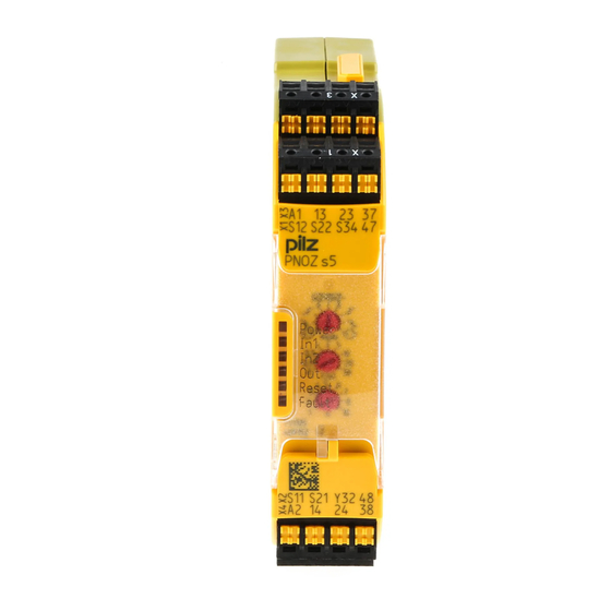
Page 9: Block Diagram/Terminal Configuration
: 48 – 240 VAC/DC; Order No. 750135, 751135 Fig.: Centre: Front view with cover, right: Front view without cover *Insulation between the non-marked area and the relay contacts: Basic insulation (over- voltage category III), Protective separation (overvoltage category II) Operating Manual PNOZ s5 21397-EN-10... -
Page 10: Function Description
Ability to increase the number of contacts available on the – instantaneous safety contacts by using connectors to link to a PNOZsigma contact expansion module – delayed/instantaneous safety contacts by connecting contact expansion modules or external contactors Operating Manual PNOZ s5 21397-EN-10... -
Page 11: Timing Diagrams
: Delay time NOTICE At the latest, the delay-on de-energisation safety contacts open after the set delay time + 20 ms + 15% of the set value, even in the case of a component failure. Operating Manual PNOZ s5 21397-EN-10... -
Page 12: Monitored Start
: Delay time NOTICE At the latest, the delay-on de-energisation safety contacts open after the set delay time + 20 ms + 15% of the set value, even in the case of a component failure. Operating Manual PNOZ s5 21397-EN-10... -
Page 13: Reset With Start-Up Test
: Recovery time NOTICE At the latest, the delay-on de-energisation safety contacts open after the set delay time + 20 ms + 15% of the set value, even in the case of a component failure. Operating Manual PNOZ s5 21397-EN-10... -
Page 14: Installation
Ensure the EMC requirements of IEC 60204-1 are met. On 24 VDC devices: The power supply must comply with the regulations for extra low voltages with protect- ive electrical separation (SELV, PELV) in accordance with VDE 0100, Part 410. Operating Manual PNOZ s5 21397-EN-10... -
Page 15: Preparing For Operation
Important for detection of shorts across contacts: As this function for detecting shorts across contacts is not failsafe, it is tested by Pilz during the final control check. If there is a danger of exceeding the cable runs, we recommend the following test after the installation of the device: 1. -
Page 16: Set Operating Modes
Delay time = 5 x 4 = 20 s The min. delay time that can be set is (when t = 0): 0.04 s. Connection Unit types with UB 48 – 240 VAC/ Supply voltage Unit types with UB 24 VDC Operating Manual PNOZ s5 21397-EN-10... - Page 17 – The operating mode selector switch must be set to "Without detection of shorts across contacts", as shorts across contacts are detected by the ESPE. Operating Manual PNOZ s5 21397-EN-10...
- Page 18 Unit types with U 24 VDC *Connect together the 0V con- nections on all the external power supplies Legend S1/S2: E-STOP/safety gate switch S3: Reset button : Switch operated : Gate open : Gate closed Operating Manual PNOZ s5 21397-EN-10...
-
Page 19: Operation
Input circuit at S12 is closed. Input circuit at S22 is closed. Safety contacts are closed and semiconductor output Y32 carries a high signal. RESET 24 VDC is present at S34. Set delay time is running. Operating Manual PNOZ s5 21397-EN-10... -
Page 20: Error Indicators
Remedy: Open both input circuits, S12 and S22, simultaneously and then close again. FAULT Diagnostics: Power-up blocked due to short-term interruption at S22; input cir- cuits not operated simultaneously Remedy: Open both input circuits, S12 and S22, simultaneously and then close again. Operating Manual PNOZ s5 21397-EN-10... -
Page 21: Faults - Malfunctions
Contact malfunctions: If the contacts have welded, reactivation will not be possible after the input circuit has opened. In the case of an error, the delay-on de-energisation contacts may open before the delay time has elapsed. Dimensions in mm *with spring-loaded terminals Operating Manual PNOZ s5 21397-EN-10... -
Page 22: Technical Details
60 ms 60 ms Current pulse, start cir- cuit 0,2 A 0,2 A 0,2 A Pulse duration, start circuit 60 ms 60 ms 60 ms Min. input resistance at power-on 110 Ohm 110 Ohm 110 Ohm Operating Manual PNOZ s5 21397-EN-10... - Page 23 Max. current Max. power 1500 VA 1500 VA 1500 VA DC1 at 24 V 24 V 24 V Min. current 0,01 A 0,01 A 0,01 A Max. current Max. power 150 W 150 W 150 W Operating Manual PNOZ s5 21397-EN-10...
- Page 24 66 A²s 66 A²s Blow-out fuse, quick Blow-out fuse, slow Blow-out fuse, gG Circuit breaker 24 V AC/DC, characteristic Contact material AgCuNi + 0,2 µm Au AgCuNi + 0,2 µm Au AgCuNi + 0,2 µm Au Operating Manual PNOZ s5 21397-EN-10...
- Page 25 With power failure max. 110 ms 110 ms 110 ms Recovery time at max. switching frequency 1/s After E-STOP 150 ms +tv 150 ms +tv 150 ms +tv After power failure 200 ms 200 ms 200 ms Operating Manual PNOZ s5 21397-EN-10...
- Page 26 EN 61326-3-1 EN 61326-3-1 Vibration In accordance with the standard EN 60068-2-6 EN 60068-2-6 EN 60068-2-6 Frequency 10 - 55 Hz 10 - 55 Hz 10 - 55 Hz Amplitude 0,35 mm 0,35 mm 0,35 mm Operating Manual PNOZ s5 21397-EN-10...
- Page 27 0,2 - 2,5 mm², 24 - 12 0,2 - 2,5 mm², 24 - 12 crimp connector – Spring-loaded terminals: Terminal points per con- nection – Stripping length with spring-loaded terminals – 9 mm 9 mm Operating Manual PNOZ s5 21397-EN-10...
- Page 28 0,2 A Pulse duration, feedback loop 60 ms 60 ms Current pulse, start circuit 0,2 A 0,2 A Pulse duration, start circuit 60 ms 60 ms Min. input resistance at power-on 110 Ohm 110 Ohm Operating Manual PNOZ s5 21397-EN-10...
- Page 29 240 V Min. current 0,01 A 0,01 A Max. current Max. power 1500 VA 1500 VA DC1 at 24 V 24 V Min. current 0,01 A 0,01 A Max. current Max. power 150 W 150 W Operating Manual PNOZ s5 21397-EN-10...
- Page 30 Max. melting integral 66 A²s 66 A²s Blow-out fuse, quick Blow-out fuse, slow Blow-out fuse, gG Circuit breaker 24 V AC/DC, characteristic B/C Contact material AgCuNi + 0,2 µm Au AgCuNi + 0,2 µm Au Operating Manual PNOZ s5 21397-EN-10...
- Page 31 80 ms 80 ms Delay-on de-energisation With E-STOP typ. 15 ms 15 ms With E-STOP max. 20 ms 20 ms With power failure typ. 75 ms 75 ms With power failure max. 110 ms 110 ms Operating Manual PNOZ s5 21397-EN-10...
- Page 32 10 - 55 Hz Amplitude 0,35 mm 0,35 mm Airgap creepage In accordance with the standard EN 60947-1 EN 60947-1 Overvoltage category III / II III / II Pollution degree Rated insulation voltage 250 V 250 V Operating Manual PNOZ s5 21397-EN-10...
-
Page 33: Safety Characteristic Data
255 g Where standards are undated, the 2014-07 latest editions shall apply. Safety characteristic data NOTICE You must comply with the safety-related characteristic data in order to achieve the required safety level for your plant/machine. Operating Manual PNOZ s5 21397-EN-10... -
Page 34: Supplementary Data
If the service life graphs are not accessible, the stated PFH value can be used irrespective of the switching frequency and the load, as the PFH value already considers the relay's B10d value as well as the failure rates of the other components. Operating Manual PNOZ s5 21397-EN-10... -
Page 35: Service Life Graph
The wear is mainly caused by the electrical load; the mechanical load is negli- gible. Switching current (A) Fig.: Service life graphs at 24 V DC and 230 V AC Switching current (A) Fig.: Service life graphs at 110 V DC Operating Manual PNOZ s5 21397-EN-10... - Page 36 To increase the service life, sufficient spark suppression must be provided on all relay con- tacts. With capacitive loads, any power surges that occur must be noted. With DC contact- ors, use flywheel diodes for spark suppression. Operating Manual PNOZ s5 21397-EN-10...
-
Page 37: Remove Plug-In Terminals
European Parliament and of the Council. The complete EC Declaration of Conformity is available on the Internet at www.pilz.com/downloads. Representative: Norbert Fröhlich, Pilz GmbH & Co. KG, Felix-Wankel-Str. 2, 73760 Ost- fildern, Germany Operating Manual PNOZ s5... - Page 38 Back cover Support Technical support is available from Pilz round the clock. Americas Australia Scandinavia Brazil +61 3 95446300 +45 74436332 +55 11 97569-2804 Spain Canada Europe +34 938497433 +1 888-315-PILZ (315-7459) Austria Switzerland Mexico +43 1 7986263-0 +41 62 88979-30...
Need help?
Do you have a question about the PNOZ s5 and is the answer not in the manual?
Questions and answers