Pilz PNOZ s30 Operating Manual
Safety relays
Hide thumbs
Also See for PNOZ s30:
- Operating manual (89 pages) ,
- Operating manual (95 pages) ,
- Operating manual (134 pages)
Table of Contents
Advertisement
Advertisement
Table of Contents

Subscribe to Our Youtube Channel
Related Manuals for Pilz PNOZ s30


Summary of Contents for Pilz PNOZ s30
- Page 1 PNOZ s30 Safety relays Operating Manual 1001715-EN-15...
- Page 2 Preface This document is a translation of the original document. All rights to this documentation are reserved by Pilz GmbH & Co. KG. Copies may be made for internal purposes. Suggestions and comments for improving this documentation will be gratefully received.
- Page 3 Section 5 Installation General installation guidelines 5.1.1 Dimensions Section 6 Commissioning Wiring 6.1.1 General wiring guidelines 6.1.2 Pin assignment of RJ45 socket 6.1.3 Supply voltage 6.1.4 Connection of proximity switches 6.1.5 Connection of a rotary encoder Operating Manual PNOZ s30 1001715-EN-15...
-
Page 4: Table Of Contents
7.1.2.3 Open circuit message 7.1.2.4 Frequency difference message on proximity switch Section 8 Technical details Safety characteristic data Section 9 Supplementary data Service life graph of output relays Categories 9.2.1 Safety level 9.2.2 Safety functions Operating Manual PNOZ s30 1001715-EN-15... - Page 5 Achievable safety level Examples 9.3.1 Connection of proximity switch 9.3.1.1 Features 9.3.1.2 Configuration overview 9.3.1.3 Connection 9.3.2 Incremental encoder connection 9.3.2.1 Features 9.3.2.2 Configuration overview 9.3.2.3 Connection Section 10 Order reference 10.1 Product 10.2 Accessories Operating Manual PNOZ s30 1001715-EN-15...
- Page 6 Introduction Introduction Validity of documentation This documentation is valid for speed monitors PNOZ s30 from version 2.2. It is valid until new documentation is published. This operating manual explains the function and operation, describes the installation and provides guidelines on how to connect the product.
- Page 7 Introduction INFORMATION This gives advice on applications and provides information on special fea- tures. Operating Manual PNOZ s30 1001715-EN-15...
- Page 8 Chip card Chip card holder Documentation on data medium 2.1.2 Unit features Using the product PNOZ s30: Speed monitor for safe monitoring of standstill, speed, speed range, position and direction. The product has the following features: Measured value recorded by –...
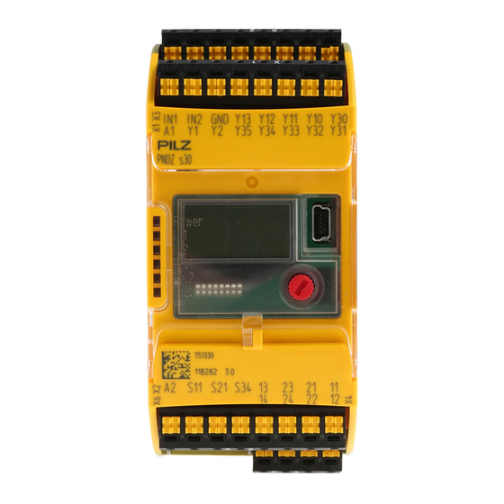
- Page 9 Proximity switch 1 - In1 (track A) and 2 - In2 (track B) and GND Y10 ... Y13: Select inputs (SEL1, SEL2, SEL4, SEL8) 13-14 and 23-24: Relay outputs (safety contacts) 11-12 and 21-22: Relay outputs (auxiliary contacts) Operating Manual PNOZ s30 1001715-EN-15...
- Page 10 1: Chip card 2: Display format 3: USB connection (service only) 4: Rotary knob 5: Expansion interface for 2 more external relay outputs LEDs: – Power – – – Rel 1 – Rel 2 – Fault Operating Manual PNOZ s30 1001715-EN-15...
- Page 11 Are familiar with the basic regulations concerning health and safety / accident preven- tion Have read and understood the information provided in this description under "Safety" And have a good knowledge of the generic and specialist standards applicable to the specific application. Operating Manual PNOZ s30 1001715-EN-15...
- Page 12 The guarantee is rendered invalid if the housing is opened or unauthorised modifica- tions are carried out. Sufficient fuse protection must be provided on all output contacts with capacitive and in- ductive loads. Operating Manual PNOZ s30 1001715-EN-15...
- Page 13 Introduction Proximity switches or rotary encoders record measured values, which are evaluated in the speed monitor PNOZ s30. There are 9 monitoring functions (F1 ... F9), which are per- formed simultaneously. Up to 16 different parameter sets (P0 ... P15) for the monitoring functions can be selected via the select inputs.
- Page 14 – Relay output 21, 22 If possible, the connections for the various earth potentials (GND, S21, Y30 und A2) should not be connected on the PNOZ s30 but should be connec- ted directly to the GNDs on the connected units, otherwise noise susceptib- ility may be increased significantly (conductor loops are not permitted).
- Page 15 With range monitoring, the output switches off if the rotational speed (velocity, frequency) is outside the configured range. Timing diagram for speed range monitoring: vmax (F3) Hys. F3 vmax (F3) - Hys. F3 vmax (F2) + Hys. F2 Hys. F2 vmax (F2) F2-F3 Operating Manual PNOZ s30 1001715-EN-15...
- Page 16 This also applies if position monitoring is used in a different switch function. Active position monitoring is reset if another parameter set is selected, which does not use position monitoring. Position monitoring cannot be used if proximity switches are employed. Operating Manual PNOZ s30 1001715-EN-15...
- Page 17 Direction monitoring is always active, irrespective of whether it is used in the selected parameter set. Direct.Right and Direct.Left are active when the PNOZ s30 is started up. Direction cannot be detected if proximity switches are used. Timing diagram for direction monitoring:...
- Page 18 Monitored start with falling edge If a monitored start with falling edge is configured, the output switches on if the speed does not reach the limit value and then a falling edge was detected at S34. Operating Manual PNOZ s30 1001715-EN-15...
- Page 19 Units The values to be configured can be entered in various units. Depending on the axis type (linear or rotational axis), various units can be selected for speed and distance (see chapter entitled "Menu overview"). Operating Manual PNOZ s30 1001715-EN-15...
- Page 20 Reset mode monitored/ Start Too short Too short pulse duration Feedback loop Rel. 1 Configuration in the example: Switch function: F2 Assigned output: Rel. 1 Delay effect on outputs: On + Off Reset mode: Monitored / Operating Manual PNOZ s30 1001715-EN-15...
- Page 21 The parameter set P2, "Automatic mode", is selected for speed monitoring (selection via the select inputs, see next chapter "Select inputs"). The following switch functions are configured for the parameter set P1: F1: Standstill 2 Hz F2: Overspeed: 50 Hz F3: Warning threshold: 50 Hz Operating Manual PNOZ s30 1001715-EN-15...
- Page 22 F3: Semiconductor output Out 1 For documentation and a better overview of the device settings, we recommend that you fill in this configuration overview before setting the device parameters (link to form, see "Cre- ate configuration overview" chapter). Operating Manual PNOZ s30 1001715-EN-15...
- Page 23 The lowest frequency (10 mHz) is automatically set for the other parameter sets (P0, P3, P5 ... P7, P9 ... P15). If one of these parameter sets is selected, an error message appears and all outputs switch off. Operating Manual PNOZ s30 1001715-EN-15...
- Page 24 Delay on the select inputs A reaction time can be entered for the select inputs. That way it is possible to filter out in- valid signals (e.g. contact bounce or an intermediate state) that occur when switching. Operating Manual PNOZ s30 1001715-EN-15...
- Page 25 P0 to P15 and switch functions F1 to F9. Direction The monitoring functions "Direct. Left" and "Direct. Right" can be configured as a switch function as often as necessary. For both directions, a tolerance can be entered for the wrong direction. Operating Manual PNOZ s30 1001715-EN-15...
- Page 26 Basic configuration 2: Rotary encoder Encoder type Rotary encoders – Rotary encoder type configurable Switch functions – Standstill (F1) – Standstill frequency configurable in Hz – Speed (F2) – Max. frequency (v max) configurable in Hz Operating Manual PNOZ s30 1001715-EN-15...
- Page 27 The cable used to connect the proximity switches must be shielded (see connection diagrams in the chapter entitled "EMC-compliant wiring"). The supply voltage of the proximity switches should be monitored via track S. Operating Manual PNOZ s30 1001715-EN-15...
- Page 28 Track S can be used: – To connect an encoder's error output – To monitor voltages between 0 V and 30 V for a permitted upper and lower limit. For example, the encoder's supply voltage can be monitored. Operating Manual PNOZ s30 1001715-EN-15...
- Page 29 AB" -> "Track AB fmax" / "Track Z" -> "Track Z fmax"). – The ratio fAB/fZ ("Encoder Settings" menu -> "Track Z" -> fAB/fZ Verh.) Please note the values stated in the technical details 4.5.2.1 Output signals Output signals TTL, HTL Single ended Differential (/Z) Operating Manual PNOZ s30 1001715-EN-15...
- Page 30 The adapter records the data between the encoder and the drive and makes it available to the PNOZ s30 via the RJ45 socket. Pilz supplies complete adapters as well as ready-made cable with RJ45 connector, which can be used when making your own adapter. The range of products in this area is con- stantly being expanded.
- Page 31 Electrostatic discharge can damage components. Ensure against discharge before touching the product, e.g. by touching an earthed, conductive sur- face or by wearing an earthed armband. 5.1.1 Dimensions *with spring-loaded terminals 98 (3.86") * 100 (3,94") (1.77") Operating Manual PNOZ s30 1001715-EN-15...
- Page 32 If possible, the connections for the various earth potentials (GND, S21, Y30, A2 ) should not be connected on the PNOZ s30 but should be connected directly to the GNDs on the connected units, otherwise noise susceptibility may be increased signific- antly (conductor loops are not permitted).
- Page 33 Invalid signals may occur with cable lengths >50 m. In this case we recommend that you connect a resistor between the signal lines, as shown in the diagrams. RJ45 pnp proximity switch with resistor R = 10 kOhm RJ45 Operating Manual PNOZ s30 1001715-EN-15...
- Page 34 Always connect GND on the encoder to GND on the RJ45 connector. 6.1.5.1 Connect rotary encoder to speed monitor Encoder types: TTL single ended HTL single ended Please note: Tracks/A, /B, Z and /Z must remain free Encoder PNOZ s30 RJ45 Operating Manual PNOZ s30 1001715-EN-15...
- Page 35 Please note: Tracks /A, /B and /Z must remain free Encoder RJ45 PNOZ s30 Encoder types: TTL differential + Z Index HTL differential + Z Index sin/cos 1 Vss Z Index Encoder PNOZ s30 RJ45 Operating Manual PNOZ s30 1001715-EN-15...
- Page 36 6.1.5.3 Connect rotary encoder to the speed monitor via an adapter The adapter (see Accessories) is connected between the encoder and the drive. The output on the adapter is connected to the RJ45 socket on the PNOZ s30. Encoder RJ45 PNOZ s30 6.1.6...
- Page 37 Hiperface (A,/A,B,/B) + Ini pnp (Z) – Hiperface (A,/A,B,/B) + HTL differential (A as Z) – Hiperface (A,/A,B,/B) + HTL single ended (A as Z) Please note: Track /Z must remain free!! Encoder PNOZ s30 RJ45 Operating Manual PNOZ s30 1001715-EN-15...
- Page 38 The unit starts up automatically when the safeguard is reset, e.g. when the E-STOP pushbutton is released. Use external circuit measures to prevent an unexpected restart. 6.1.8 Feedback circuit No feedback loop monitoring Contacts from external contactors 6.1.9 Select inputs 6.1.10 Semiconductor outputs Operating Manual PNOZ s30 1001715-EN-15...
- Page 39 A or B or C or D or E Conductor loops outside the shield must be avoided. If a shielded junction box is not used, the shield must run continuously from the sensor to the evaluation device. Operating Manual PNOZ s30 1001715-EN-15...
- Page 40 A or B or C or D or E Conductor loops outside the shield must be avoided. If a shielded junction box is not used, the shield must run continuously from the sensor to the evaluation device. Operating Manual PNOZ s30 1001715-EN-15...
- Page 41 A or B or C or D or E Conductor loops outside the shield must be avoided. If a shielded junction box is not used, the shield must run continuously from the sensor to the evaluation device. Operating Manual PNOZ s30 1001715-EN-15...
- Page 42 Release knob (B) and push it back into the unit: – Press the bar on the side of the knob [1] towards the centre of the knob. This re- leases the knob. – Press the knob downwards [2] while keeping the bar pressed in Operating Manual PNOZ s30 1001715-EN-15...
- Page 43 If no value is set or amended within 30 s of a menu action, the display re- verts to the default display. The current setting remains unchanged. If the master password has been entered, this time increases to 5 minutes. Operating Manual PNOZ s30 1001715-EN-15...
- Page 44 Please Insert SIM Card!. If you change the parameters, the Please Insert SIM Card! message will re- appear. The message disappears after 30 s or by pressing the rotary knob. Operating Manual PNOZ s30 1001715-EN-15...
- Page 45 For this reason please protect the chip card's contact surface from – Contamination – Contact – Mechanical impact, such as scratches. Make sure that you do not bend the chip card as you insert it into the chip card slot. Operating Manual PNOZ s30 1001715-EN-15...
- Page 46 Commissioning 6.2.5.2 Write data to chip card If you are inserting a chip card which has not yet been written by a PNOZ s30, you have the option to: Insert Data is written to the chip card chip card Please insert...
- Page 47 You can also create copies of a chip card and its data. Proceed as follows: Remove chip card containg the device data. Insert a new chip card into the device. Confirm the message Write configuration to SIM Yes?. The new chip card is written. Operating Manual PNOZ s30 1001715-EN-15...
- Page 48 97]). Save PNOZ s30 configuration on the computer 1. Make a note of the configuration's CRC in the PNOZ s30. It is shown on the display in the Information/ Configuration CRC menu. This will be needed later to check whether the correct configuration is saved on the device.
-
Page 49: Permanent Display
2. Start the SmartCardCommander software. 3. To write the chip card, select Write Data to Card and confirm with Yes. 4. Insert the chip card in the PNOZ s30 and proceed as described under Read data from chip card [ 46]. -
Page 50: Basic Settings Ini Pnp Pnp
Standstill: Relay output Rel.1 and semiconductor output Out 1 – Speed: Relay output Rel.2 and semiconductor output Out 2 Start mode – Rel.1 and semiconductor output Out 1, Rel.2 , Out 1, Out 2: Automatic start "Auto- matic" Operating Manual PNOZ s30 1001715-EN-15... -
Page 51: Basic Settings For The Rotary Encoder
-Hiperface (A, /A, B, /B) Standstill Enter standstill frequency 10 mHz to 1.00 kHz Rel.1 Out 1 Default 100 Hz v max Enter the max. permitted speed 10 mHz to 1.00 MHz Rel.2 Out 2 Default 5.00 kHz Operating Manual PNOZ s30 1001715-EN-15... - Page 52 Left direction: External output Ext. 1 and semiconductor output Out 3 – Right direction: External output Ext. 2 and semiconductor output Out 4 Start mode – All outputs: Automatic start ("Automatic") Switch delay None Max. encoder frequency 1 MHz Operating Manual PNOZ s30 1001715-EN-15...
- Page 53 1 m = x Imp (x = 1 ... 10,000,000 pulses) 1 rot = x Imp (x = 1 ... 10,000,000 pulses) Encoder Settings Create encoder configuration for the tracks A, /A, B, /B, Z, /Z, S Operating Manual PNOZ s30 1001715-EN-15...
-
Page 54: Settings
Sin/Cos 1 Vss - sin/cos 1 Vss (A, /A, B, /B) Sin/Cos 1 Vss with Z-Index - sin/cos 1 Vss Z Index (A, /A, B, /B, Z, / Hiperface - Hiperface (A, /A, B, /B) Operating Manual PNOZ s30 1001715-EN-15... - Page 55 Select direction for tracks A and B - Normal Information: Default - Inverted This function is used to display a Normal forward movement as positive lin- ear/rotational speed, irrespective of the installation of the rotary en- coder. Operating Manual PNOZ s30 1001715-EN-15...
- Page 56 Enter result as ratio fAB to fZ Track S Settings for track S (error track) Track S Use of track S: - Not used Default -Not used (track S is not used) - Evaluation Not used -Evaluation (track S is used) Operating Manual PNOZ s30 1001715-EN-15...
- Page 57 " (see above) (F1 ... F9) Select linear/rotational speed limit 10 mHz ... 1.00 MHz (P0 ... P15) or the corresponding value in the selec- ted unit -v max: : 2.00 kHz Operating Manual PNOZ s30 1001715-EN-15...
- Page 58 ((Rel.1 ... Out 4) ) - Monitored / Automatic: Automatic start Default -Monitored \ Monitored /: Monitored start with Monitored / rising edge at S34 Monitored \: Monitored start with falling edge at S34 Operating Manual PNOZ s30 1001715-EN-15...
-
Page 59: Advanced Settings
- Off switching off, or switching on and Default -OnOff off. On delay Delay Time Select delay time for the respect- 0 ... 30.0 s ive output (Rel.1 ... Out 4) Default tdO: 0 ms Operating Manual PNOZ s30 1001715-EN-15... -
Page 60: Information
Max. measured linear/rotational 0 … 4.29 MHz speed at tracks A and B Track AB or the corresponding value in the set The value can be reset to 0 unit Reset: Reset: - Yes ? - No Operating Manual PNOZ s30 1001715-EN-15... - Page 61 2nd + 3rd line: Plain text to describe er- (can be rectified by user) ror for the user System errors: Level 2 and 3 Level 3: (internal error, information for Pilz 1st line: Seq. No. "Repairable" Service). 2nd line: "System time" See section entitled "Error stack 3rd line: System time when the error entries"...
- Page 62 1st line: Seq. No. "Err.:", error number System errors: Level 2 and 3 2nd + 3rd line: Plain text to describe er- ror for the user (internal error, information for Pilz Service). Level 3: The error messages can be hid- 1st line: Seq.
- Page 63 -> Select whether the data on the chip card is to be saved. Password mes- sages Master PW -> Enter master password 0000 ... 9999 Default Password: 0000 Password: -> Enter customer password 0000 ... 9999 Default 0000 Operating Manual PNOZ s30 1001715-EN-15...
-
Page 64: Example: Configure Basic Configuration 2
>Standstill Rel.1 Out 1 Rel.1 Out 1 300 Hz 300 Hz save? max: F1 S0 Standstill Rel.1 Out 1 300 Hz 300 Hz save? v max: Rel.2 Out 2 5,00 kHz Basic Settings Enc. ESCAPE Operating Manual PNOZ s30 1001715-EN-15... -
Page 65: Operation
Error on relay output 1 Relay output 2 is switched on Error on relay output 2 Fault that can be repaired by the user leading to safe condition. Internal error leading to a safe condition. Operating Manual PNOZ s30 1001715-EN-15... -
Page 66: Display
Remedy: Rectify error; if necessary, contact Pilz – Internal errors (system errors, all errors that are not described in the list) Remedy: Switch device on and off, contact Pilz 7.1.2.2 Current error messages If an error is detected, the "Fault" LED lights up on the device and an error message ap- pears on the display (see error stack). - Page 67 -Ensure that the expansion module open module operates correctly 4012 Extension Interface open The termin- -Connect terminator ator on the -Ensure that the expansion expansion in- module operates correctly terface is not connected Operating Manual PNOZ s30 1001715-EN-15...
- Page 68 A low signal -Ensure that the encoders are is always configured correctly present at -Ensure that the encoder oper- track A or /A. ates correctly -Ensure that there is no short circuit in the wiring Operating Manual PNOZ s30 1001715-EN-15...
- Page 69 Signal error AB: Sin2 Cos2 No feasible -Ensure that the encoders are signal at the configured correctly tracks AB -Ensure that the encoder oper- ates correctly -Ensure that the wiring is correct -Check supply voltage Operating Manual PNOZ s30 1001715-EN-15...
- Page 70 -Ensure that the encoders are time configured correctly -Ensure that the proximity switches operate correctly -Ensure that the supply voltage is present at the proximity switches Ensure that the proximity switches are wired correctly Operating Manual PNOZ s30 1001715-EN-15...
- Page 71 /A configured correctly -Ensure that the wiring is correct 10261 Ini Signal /B Not permitted Invalid signal -Ensure that the encoders are at track /B configured correctly -Ensure that the wiring is correct Operating Manual PNOZ s30 1001715-EN-15...
- Page 72 Signal error Track A or B No feasible -Ensure that the encoders are signal at the configured correctly tracks AB -Ensure that the encoder oper- ates correctly -Ensure that the wiring is correct -Check supply voltage. Operating Manual PNOZ s30 1001715-EN-15...
-
Page 73: Open Circuit Message
(see "Current error messages"), all outputs will switch off and the Fault LED will light up. The error message disappears automatically if Valid signals, greater than the global standstill frequency, are detected from both prox- imity switches A falling edge is detected at start input S34 Operating Manual PNOZ s30 1001715-EN-15... - Page 74 - Check whether a proximity switch quency of the proximity constantly switches due to the switch at track B for too drive's edge jitter. long and by too much. Operating Manual PNOZ s30 1001715-EN-15...
-
Page 75: Technical Details
0 - 1.000 kHz Configurable monitoring frequency Without hysteresis 10 mHz - 1.000 kHz 10 mHz - 1.000 kHz Inputs 750330 751330 Voltage at Start circuit DC 24,0 V 24,0 V Feedback loop DC 24,0 V 24,0 V Operating Manual PNOZ s30 1001715-EN-15... - Page 76 DC1 at 24 V 24 V Min. current 0,01 A 0,01 A Max. current 4,0 A 4,0 A Max. power 100 W 100 W Utilisation category In accordance with the standard EN 60947-5-1 EN 60947-5-1 Operating Manual PNOZ s30 1001715-EN-15...
- Page 77 With power failure typ. UB 240 V 100 ms 100 ms With power failure max. UB 240 150 ms 150 ms After safety function is triggered typ. 8 ms 8 ms After safety function is triggered max. 15 ms 15 ms Operating Manual PNOZ s30 1001715-EN-15...
- Page 78 Mounting area (e.g. control cab- inet) IP54 IP54 Housing IP30 IP30 Terminals IP20 IP20 Mechanical data 750330 751330 Mounting position Horizontal on top hat rail Horizontal on top hat rail Mechanical life 10,000,000 cycles 10,000,000 cycles Operating Manual PNOZ s30 1001715-EN-15...
- Page 79 – 9 mm Dimensions Height 98,0 mm 100,0 mm Width 45,0 mm 45,0 mm Depth 120,0 mm 120,0 mm Weight 410 g 410 g Where standards are undated, the 2009-06 latest editions shall apply. Operating Manual PNOZ s30 1001715-EN-15...
-
Page 80: Safety Characteristic Data
If the service life graphs are not accessible, the stated PFH value can be used irrespective of the switching frequency and the load, as the PFH value already considers the relay's B10d value as well as the failure rates of the other components. Operating Manual PNOZ s30 1001715-EN-15... -
Page 81: Supplementary Data
To increase the service life, sufficient spark suppression must be provided on all relay con- tacts. With capacitive loads, any power surges that occur must be noted. With DC contact- ors, use flywheel diodes for spark suppression. Operating Manual PNOZ s30 1001715-EN-15... -
Page 82: Categories
PNOZ s30. INFORMATION The safety-related characteristic data of the PNOZ s30 and all other devices that are used must be taken into account when calculating the safety level. We recommend that you use the PAScal software tool to calculate the safety function's SIL/PL values. -
Page 83: Safety Functions
Direction Monitoring for broken shearpins The safety functions of the PNOZ s30 are monitoring functions, whereby a safe output sig- nal is used to show if defined limit values are exceeded. The reaction function that takes place (e.g. shutting down the drive, activating a mechanical... -
Page 84: Safety-Related Architecture
Supplementary data 9.2.3.2 Safety-related architecture To calculate the safety function you will need the following data for the "sensor" subsystem and "PNOZ s30" subsystem: Sensor PNOZ s30 subsystem Category MTTFd Operating mode PFH (1/h) Manufacturer- Monitoring 2,34-08 specific 1 encoder *In accordance with EN ISO 13849-1, Category 1 is only met if the sensor is a "well-tried... -
Page 85: Safety-Related Architecture
Actuator Sensor PNOZ s30 Actuator non-safe encoder Logic Diagnostic To calculate the safety function you will need the following data for the "sensor" subsystem and "PNOZ s30" subsystem: Sensor PNOZ s30 subsystem Category MTTFd Operating mode PFH (1/h) Manufacturer- 90 % Monitoring... -
Page 86: Requirements Of The Drive Controller
PNOZ s30 Actuator non-safe encoder Logic Diagnostic Drive Control Diagnostic To calculate the safety function you will need the following data for the "sensor" subsystem and "PNOZ s30" subsystem: Sensor PNOZ s30 subsystem Category MTTFd Operating mode PFH (1/h) Manufacturer-... -
Page 87: Achievable Safety Level
Sensor PNOZ s30 Actuator safe encoder Logic Diagnostic To calculate the safety function you will need the following data for the "sensor" subsystem and "PNOZ s30" subsystem: Sensor PNOZ s30 subsystem PFH (1/ Operating mode PFH (1/h) See manufacturer Monitoring... -
Page 88: Achievable Safety Level
SRP/CS SRP/CS Sensor Logic Actuator Sensor PNOZ s30 Actuator safe encoder with Logic track Z Diagnostic To calculate the safety function you will need the following data for the "sensor" subsystem and "PNOZ s30" subsystem: Operating Manual PNOZ s30 1001715-EN-15... -
Page 89: Achievable Safety Level
Square output signals HTL, single ended Square output signals HTL, differential Sin/Cos output signals 1Vss, reference voltage Sin/Cos output signals 1Vss, differential Reference sensor Permitted encoder types: Rotary non-safety-related encoders Linear non-safety-related encoders Inductive proximity switches Operating Manual PNOZ s30 1001715-EN-15... -
Page 90: Safety-Related Architecture
PNOZ s30 Actuator non-safe encoder Logic Diagnostic Sensor proximity switch To calculate the safety function you will need the following data for the "sensor" subsystem and "PNOZ s30" subsystem: Sensor PNOZ s30 subsystem Category MTTFd Operating mode PFH (1/h) Manufacturer-... -
Page 91: Safety-Related Characteristic Data For Operation With 2 Proximity Switches
SRP/CS SRP/CS Sensor Logic Actuator Sensor PNOZ s30 Actuator proximity switch Logic Diagnostic Sensor proximity switch To calculate the safety function you will need the following data for the "sensor" subsystem and "PNOZ s30" subsystem: Operating Manual PNOZ s30 1001715-EN-15... -
Page 92: Achievable Safety Level
Feedback loop monitoring for Rel.1 via feedback loop input Y1, Feedback loop monitoring for Rel.2 via feedback loop input Y2 Automatic reset Encoder The measured values are detected by two proximity switches (pnp). PNOZ s4 Safety gate monitoring Operating Manual PNOZ s30 1001715-EN-15... -
Page 93: Configuration Overview
Supplementary data 9.3.1.2 Configuration overview Operating Manual PNOZ s30 1001715-EN-15... -
Page 94: Connection
Overspeed is detected during automatic mode at >= 3000 Hz and the output Rel. 2 switches off. – If a speed of 2800 Hz is exceeded, the semiconductor output Out1 switches in auto- matic mode and a message (advance warning) is output via the PLC. Operating Manual PNOZ s30 1001715-EN-15... -
Page 95: Configuration Overview
Standstill is detected at <= 2 Hz for both operating modes and the output Rel. 1 switches on. Feedback loop monitoring via feedback inputs Y1 and Y2 Encoder: The measured values are detected by an incremental encoder (sin/cos) 9.3.2.2 Configuration overview Operating Manual PNOZ s30 1001715-EN-15... -
Page 96: Connection
Supplementary data 9.3.2.3 Connection Y12 Y11 24 V Y35 Y34 PNOZ s30 S11 S21 S34 Input Drive device * The PNOZ msi adapters are available from Pilz as accessories Operating Manual PNOZ s30 1001715-EN-15... -
Page 97: Order Reference
Adapter and cable Lenze 9-pin, 1.5 m 773 863 PNOZ msi9p Adapter cable 5.0 m 773 856 PNOZ msi10p Adapter cable 2.5 m 773 854 PNOZ msi11p Adapter cable 1.5 m 773 855 PNOZ msi19p Connection cable, 1.5 m 773 846 Operating Manual PNOZ s30 1001715-EN-15... - Page 98 750 031 adapter saving the configuration on the computer PNOZsigma Chip Card manager set Set consisting of the PNOZ Chip Card Reader 750 030 and SmartCardCommander with SIM card ad- apter (779 230 and 750 030) Operating Manual PNOZ s30 1001715-EN-15...
- Page 99 Front cover Support Technical support is available from Pilz round the clock. Americas Australia Scandinavia Brazil +61 3 95446300 +45 74436332 +55 11 97569-2804 Spain Canada Europe +34 938497433 +1 888-315-PILZ (315-7459) Austria Switzerland Mexico +43 1 7986263-0 +41 62 88979-30...
Need help?
Do you have a question about the PNOZ s30 and is the answer not in the manual?
Questions and answers