Pilz PNOZ s30 Operating Manual
Safety relays
Hide thumbs
Also See for PNOZ s30:
- Operating manual (89 pages) ,
- Operating manual (99 pages) ,
- Operating manual (95 pages)
Table of Contents
Advertisement
Quick Links
Advertisement
Table of Contents

Subscribe to Our Youtube Channel
Related Manuals for Pilz PNOZ s30


Summary of Contents for Pilz PNOZ s30
- Page 1 PNOZ s30 Safety relays Operating Manual-1001715-EN-19...
- Page 2 We do assure you that all persons are regarded without discrim- ination and on an equal basis. All rights to this documentation are reserved by Pilz GmbH & Co. KG. Copies may be made for the user's internal purposes. Suggestions and comments for improving this documenta- tion will be gratefully received.
-
Page 3: Table Of Contents
Switch delay ..........................26 5.3.14 Feedback loops.........................26 5.3.15 Analogue output ........................27 5.3.16 Units ............................27 5.3.17 Timing diagram for speed monitoring..................28 Speed configuration ........................29 5.4.1 Select Inputs ..........................31 5.4.2 Switch functions ........................33 5.4.3 Special functions ........................35 5.4.4 Basic configuration........................37 Operating Manual PNOZ s30 1001715-EN-19... - Page 4 Special cases and problem solving...................64 Save configuration with Software SmartCardCommander............65 Menu overview ..........................67 8.7.1 Permanent display ........................67 8.7.2 Basic settings Ini pnp pnp ......................67 8.7.3 Basic settings for the rotary encoder..................68 8.7.4 Settings .............................70 8.7.5 Advanced settings........................78 Operating Manual PNOZ s30 1001715-EN-19...
- Page 5 13.3.5.2 Requirements of the drive controller ..................117 13.3.5.3 Safety-related architecture ......................117 13.3.5.4 Achievable safety level......................118 13.3.6 Safety-related characteristic data for operation with a safe rotary encoder ......118 13.3.6.1 Permitted encoder types and output signals ................118 Operating Manual PNOZ s30 1001715-EN-19...
- Page 6 Connection of proximity switch....................125 13.4.1.1 Features ............................125 13.4.1.2 Configuration overview......................125 13.4.2 Incremental encoder connection ....................127 13.4.2.1 Features ............................127 13.4.2.2 Configuration overview......................127 Order reference ........................129 14.1 Product............................129 14.2 Accessories..........................129 EC declaration of conformity ....................132 UKCA-Declaration of Conformity ..................133 Operating Manual PNOZ s30 1001715-EN-19...
-
Page 7: Introduction
Introduction Introduction Validity of documentation This documentation is valid for the product PNOZ s30 from Version 3.1. This operating manual explains the function and operation, describes the installation and provides guidelines on how to connect the product. Using the documentation This document is intended for instruction. - Page 8 Introduction INFORMATION This gives advice on applications and provides information on special fea- tures. Operating Manual PNOZ s30 1001715-EN-19...
-
Page 9: Overview
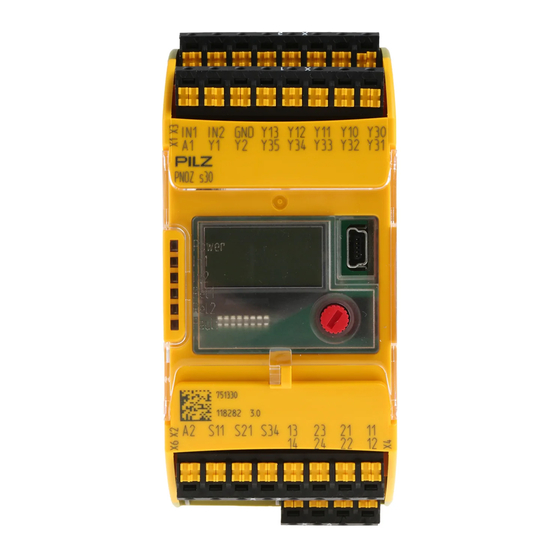
Chip card Chip card holder 2.1.2 Unit features Application of the product PNOZ s30: Speed monitor for safe monitoring of standstill, speed, speed range, position and direction. The product has the following features: Measured value recorded by – Incremental encoder –... -
Page 10: Front/Side View
Y10 ... Y13: Select inputs (SEL1, SEL2, SEL4, SEL8) 13-14 and 23-24: Relay outputs REL 1 and REL 2 (safety contacts) 11-12 and 21-22: Relay outputs REL 1 and REL 2 (auxiliary contacts) Operating Manual PNOZ s30 | 10 1001715-EN-19... - Page 11 1: Chip card 2: Display 3: USB connection 4: Rotary knob 5: Expansion interface for 2 more external relay outputs LEDs: – Power – In1 – In2 – Rel 1 – Rel 2 – Fault Operating Manual PNOZ s30 | 11 1001715-EN-19...
-
Page 12: Safety
EN ISO 13849 and EN 62061. However, this does not guarantee the functional safety of the overall plant/machine. To achieve the relevant safety level of the overall plant/ machine’s required safety functions, each safety function needs to be considered separ- ately. Operating Manual PNOZ s30 | 12 1001715-EN-19... -
Page 13: Use Of Qualified Personnel
The guarantee is rendered invalid if the housing is opened or unauthorised modifications are carried out. Adequate protection must be provided on all output contacts with capacitive and inductive loads. Operating Manual PNOZ s30 | 13 1001715-EN-19... -
Page 14: Security
The configuration computer that accesses the product has to be protected from attacks by a firewall or other suitable measures. We recommend that a virus scanner is used on this configuration computer and updated regularly. Operating Manual PNOZ s30 | 14 1001715-EN-19... -
Page 15: Function Description
Introduction Proximity switches or encoders record measured values, which are evaluated in the speed monitor PNOZ s30. Up to 9 monitoring functions can be configured (F1 ... F9) which are run at a time. Via the Select inputs, up to 16 different parameter sets (P0 ... P15) of the monitoring func- tion can be chosen, e.g. -
Page 16: Functions
– Relay output 21, 22 If possible, the connections for the various earth potentials (GND, S21, Y30 und A2) should not be connected on the PNOZ s30 but should be connec- ted directly to the GNDs on the connected units, otherwise noise susceptib- ility may be increased significantly (conductor loops are not permitted). -
Page 17: Speed
With range monitoring, the output switches off if the rotational speed (velocity, frequency) is outside the configured range. vmax (F3) Hys. F3 vmax (F3) - Hys. F3 vmax (F2) + Hys. F2 Hys. F2 vmax (F2) F2-F3 Fig.: Sequence of speed range monitoring process Operating Manual PNOZ s30 | 17 1001715-EN-19... -
Page 18: Position
Start of position monitoring by rising edge at the start input (S34) Position leaves the position window, assigned outputs will switch off Restart of position monitoring by rising edge at the start input (S34) Position leaves the position window, assigned outputs will switch off Operating Manual PNOZ s30 | 18 1001715-EN-19... - Page 19 Position monitoring cannot be used if proximity switches are employed. Managing the start type of the outputs is independent of the start type of the position monitoring. In the event of an open circuit, position monitoring is automatically deactivated Operating Manual PNOZ s30 | 19 1001715-EN-19...
-
Page 20: Direction
Direction monitoring is always active, irrespective of whether it is used in the selected parameter set. Direct.Right and Direct.Left are active when the PNOZ s30 is started up. Direction cannot be detected if proximity switches are used. Timing diagram for direction monitoring:... -
Page 21: Encoder Diagnostics / Broken Shearpin Monitoring
The hysteresis becomes effective when the output is switched on: Switch-on value = switching threshold – hysteresis For the lower range limit: Switch-on value = switching threshold + hysteresis Operating Manual PNOZ s30 | 21 1001715-EN-19... -
Page 22: Frequency Filtering
The reaction time after the limit value is exceeded, as specified in the tech- nical details, is increased by filtering. Effect of frequency filtering, as an example Time [s] Unfiltered Filter (average) Filter (fast) Filter (slow) Operating Manual PNOZ s30 | 22 1001715-EN-19... - Page 23 The diagram shows the reaction of the average filter to a speed change at the input. The fil- ter achieves 99% of the set end value after approx. 47 ms. Operating Manual PNOZ s30 | 23 1001715-EN-19...
-
Page 24: Start Types
S34. 5.3.10 Start-up delay A start-up delay time can be configured, which prevents the evaluation of the encoder sig- nals for the configured time period after the supply voltage is switched on. Operating Manual PNOZ s30 | 24 1001715-EN-19... -
Page 25: Synchronous Start
External outputs on the expansion interface The external outputs Ext.1 and Ext. 2 can be used for more safe relay outputs. To do this, connect an appropriate expansion module to the expansion interface. Operating Manual PNOZ s30 | 25 1001715-EN-19... -
Page 26: Switch Delay
A rising edge during the delay time has no effect. The output switches off when the time has elapsed. 5.3.14 Feedback loops Feedback loops are used to monitor external contactors or relays. The corresponding feed- back loop must be closed before starting. Operating Manual PNOZ s30 | 26 1001715-EN-19... -
Page 27: Analogue Output
The values to be configured can be entered in various units. Depending on the axis type (linear or rotational axis), various units can be selected for speed and distance (see chapter entitled "Menu overview"). Operating Manual PNOZ s30 | 27 1001715-EN-19... -
Page 28: Timing Diagram For Speed Monitoring
Start Too short Too short pulse duration Feedback loop Rel. 1 Configuration in the example: Switch function: F2 Assigned output: Rel. 1 Delay effect on outputs: On + Off Start type: Monitored / Operating Manual PNOZ s30 | 28 1001715-EN-19... -
Page 29: Speed Configuration
The parameter set P1, "Automatic mode", is selected for speed monitoring (selection via the Select inputs, see next chapter "Select inputs"). The following switching functions are configured for the parameter set P0: F1: Standstill 2 Hz F2: Overspeed: 50Hz F3: Warning threshold: 50Hz Operating Manual PNOZ s30 | 29 1001715-EN-19... - Page 30 (see under Create con- figuration overview [ 56]). From device version 2.2 you have the opportunity to create the settings with the software- tool from Pilz (see Create configuration in PNOZsigma Configurator [ 87]). Operating Manual PNOZ s30 | 30 1001715-EN-19...
-
Page 31: Select Inputs
Open circuit Drift in the inputs This may mean that a parameter set other than P1, P2, P4 or P8 is selected. An error mes- sage appears and all the outputs switch off. Operating Manual PNOZ s30 | 31 1001715-EN-19... - Page 32 A reaction time can be entered for the select inputs. That way it is possible to filter out in- valid signals (e.g. contact bounce or an intermediate state) that occur when switching. The new parameter set will be activated only when the delay time has elapsed. Operating Manual PNOZ s30 | 32 1001715-EN-19...
-
Page 33: Switch Functions
The static value "On" or "Off" can be configured as a switch function instead of a monitor- ing function. The assigned outputs are then switched on and/or off. The static value "On" and "Off" can be configured as a switch function as often as neces- sary. Operating Manual PNOZ s30 | 33 1001715-EN-19... - Page 34 Every assignment has a unique number. The assignment options are available: On the display Description Individual switch functions … F2 - F3 Speed range F4 - F5 F6 - F7 F8 - F9 Error output Operating Manual PNOZ s30 | 34 1001715-EN-19...
-
Page 35: Special Functions
For a parameter set with the special function "No 2 encoder diagnostics" the operating mode without Z Freq. Ini pnp must be used for the safety assessment. Please note that the "Select inputs mode" setting may reduce the safety level (see under Select Inputs [ 31]). Operating Manual PNOZ s30 | 35 1001715-EN-19... - Page 36 A complete list of recoverable errors can be found under Current error messages [ 92]. The error acknowledgement restarts the PNOZ s30. Restart The device is restarted when switching to the parameter set. After restart the device behaves in accordance with the switching functions configured in this parameter set.
-
Page 37: Basic Configuration
– Speed (F2): Relay output Rel. 2 and semiconductor output Out 2 Start mode – Rel. 1, Rel. 2 Out 1, Out 2: Automatic start Switch delay None Max. encoder frequency 3.5 kHz Basic configuration 2: Encoder Encoder type Encoder – Encoder type configurable Operating Manual PNOZ s30 | 37 1001715-EN-19... -
Page 38: Chip Card
The set parameters, the name of the configuration, the check sum and the passwords are stored on the chip card. The error list can also be saved to the chip card. (See chapter "Use chip card"). Operating Manual PNOZ s30 | 38 1001715-EN-19... -
Page 39: Input Device Types
Please note the values stated in the technical details The maximum frequency of the used encoders must be entered for a full configuration ("Encoder" menu → "Track AB" → "Track AB fmax" / "Track Z" → "Track Z fmax"). Operating Manual PNOZ s30 | 39 1001715-EN-19... -
Page 40: Rotary Encoders
– Tolerance time for tracks A and B ("Encoder" menu → "Track AB" → "Track AB Tol.") – Tolerance time for track Z ("Encoder" menu → "Track Z" → "Track Z Tol.") – Tolerance time for track S ("Encoder" menu → "Track S" → "Track S Tol.") Operating Manual PNOZ s30 | 40 1001715-EN-19... -
Page 41: Output Signals
This must be taken into account when the system is designed. Please note the values stated in the technical details 5.5.2.1 Output signals Output signals TTL, HTL Single ended Differential (/Z) Operating Manual PNOZ s30 | 41 1001715-EN-19... -
Page 42: Adapter For Incremental Encoders
The adapter records the data between the encoder and the drive and makes it available to the PNOZ s30 via the RJ45 socket. Pilz supplies complete adapters as well as ready-made cable with RJ45 connector, which can be used when making your own adapter. The range of products in this area is con- stantly being expanded. -
Page 43: Installation
Electrostatic discharge can damage components. Ensure against discharge before touching the product, e.g. by touching an earthed, conductive sur- face or by wearing an earthed armband. 6.1.1 Dimensions *with spring-loaded terminals 98 (3.86") * 100 (3,94") (1.77") Operating Manual PNOZ s30 | 43 1001715-EN-19... -
Page 44: Wiring
If possible, the connections for the various earth potentials (GND, S21, Y30, A2 ) should not be connected on the PNOZ s30 but should be connected directly to the GNDs on the connected units. otherwise noise susceptibility may be increased significantly (conductor loops are not permitted). -
Page 45: Connection Of Proximity Switches
Special features when connecting 2 proximity switches with reduced diagnostics: The cables for connecting the proximity switches must be laid separately. The supply voltage to the proximity switches must be monitored, via track S for example. RJ45 Operating Manual PNOZ s30 | 45 1001715-EN-19... -
Page 46: Connection Of A Rotary Encoder
Always connect GND on the encoder to GND on the RJ45 connector. INFORMATION The following diagrams are principle connection diagrams. For better clarity, the shielding and supply voltage are not shown. Operating Manual PNOZ s30 | 46 1001715-EN-19... -
Page 47: Connect Rotary Encoder To Speed Monitor
Connect rotary encoder with Z index to speed monitor Encoder types: TTL single ended Z Index HTL single ended Z Index Please note: Tracks /A, /B and /Z must remain free Encoder RJ45 PNOZ s30 Operating Manual PNOZ s30 | 47 1001715-EN-19... -
Page 48: Connect Rotary Encoder To The Speed Monitor Via An Adapter
7.5.3 Connect rotary encoder to the speed monitor via an adapter The adapter (see Accessories) is connected between the encoder and the drive. The output on the adapter is connected to the RJ45 socket on the PNOZ s30. Encoder RJ45... - Page 49 – sin/cos 1 Vss (A,/A,B,/B) + HTL single ended (A as Z) Configuration: Hiperface Z Freq. Ini pnp – Hiperface (A,/A,B,/B) + Ini pnp (Z) – Hiperface (A,/A,B,/B) + HTL differential (A as Z) – Hiperface (A,/A,B,/B) + HTL single ended (A as Z) Operating Manual PNOZ s30 | 49 1001715-EN-19...
-
Page 50: Reset Circuit
When using the feedback loop, the cable run at S34, Y1, Y2 and S11 may be max. 30 m. For greater cable runs, shielded cables with earthing at either end must be used. Operating Manual PNOZ s30 | 50 1001715-EN-19... -
Page 51: Select Inputs
To avoid EMC interference we recommend that the shield on the sensor cables or the housing of the shielded junction box is only connected to earth at a single point: A or B or C or D or E Operating Manual PNOZ s30 | 51 1001715-EN-19... - Page 52 A or B or C or D or E Conductor loops outside the shield must be avoided. If a shielded junction box is not used, the shield must run continuously from the sensor to the evaluation device. Operating Manual PNOZ s30 | 52 1001715-EN-19...
- Page 53 A or B or C or D or E Conductor loops outside the shield must be avoided. If a shielded junction box is not used, the shield must run continuously from the sensor to the evaluation device. Operating Manual PNOZ s30 | 53 1001715-EN-19...
- Page 54 A or B or C or D or E or F Conductor loops outside of the shield must be avoided. If a shielded connection box is not used, the shield must run uninterrupted from the sensor to the evaluation device. Operating Manual PNOZ s30 | 54 1001715-EN-19...
- Page 55 A or B or C or D or E or F or G Conductor loops outside of the shield must be avoided. If a shielded connection box is not used, the shield must run uninterrupted from the sensor to the evaluation device. Operating Manual PNOZ s30 | 55 1001715-EN-19...
-
Page 56: Display Menu - Configuration
Pilz (see Create configuration in PNOZsigma Configurator [ 87]). Create configuration overview For a better overview, before entering the configuration values we recommend that they are entered in the attached form PNOZ_s30_Config_Overview: Operating Manual PNOZ s30 | 56 1001715-EN-19... -
Page 57: Operate Rotary Knob
The speed with which you turn the knob affects the sequence of the menu and numeric val- ues: Slowly: Units Quickly: Tens Very quickly: – Setting the numeric value: Hundreds – When switching the menu level: Jump to ESCAPE Operating Manual PNOZ s30 | 57 1001715-EN-19... -
Page 58: Password Protection
If the settings are reset to the factory settings, the passwords and the language will also be reset to the factory settings. The passwords can be changed at any time in the menu. Enter a 4-figure password. Operating Manual PNOZ s30 | 58 1001715-EN-19... -
Page 59: Use Chip Card
Please Insert SIM Card!. If you change the parameters, the Please Insert SIM Card! message will re- appear. The message disappears after 30 s or by pressing the rotary knob. Operating Manual PNOZ s30 | 59 1001715-EN-19... -
Page 60: Insert Chip Card
Make sure that you do not bend the chip card as you insert it into the chip card slot. 8.5.2 Write data to chip card If you are inserting a chip card which has not yet been written by a PNOZ s30, you have the option to: Insert... -
Page 61: Read Data From Chip Card
Do not allow data to be written to the chip card 8.5.3 Read data from chip card If you are inserting a chip card which has not yet been written by a PNOZ s30, you have the option to: Insert chip card (data... -
Page 62: Transfer Device Parameters
To transfer the device parameters, proceed as follows: Make a note of the configuration's CRC in the PNOZ s30. It is shown on the display in the Information/ Configuration CRC menu. This will be needed later, to check whether the correct configuration is saved on the device. -
Page 63: Compatibility With Older Device Versions
Current Upgrade SIM: Upgrade SIM: Current menu menu New CRC: 12345 New CRC: (0…65535) 12345 (0… 65535) Yes? Allow the new configuration to be written to the chip card Operating Manual PNOZ s30 | 63 1001715-EN-19... -
Page 64: Special Cases And Problem Solving
Do not allow the new configuration to be written to the chip card If a chip card from a PNOZ s30 with an older device version was loaded and afterwards a new chip card was inserted, it may also be necessary to update the configuration. See plicate chip card [ 62]. -
Page 65: Save Configuration With Software Smartcardcommander
129]). Save PNOZ s30 configuration on the computer 1. Make a note of the configuration's CRC in the PNOZ s30. It is shown on the display in the Information/ Configuration CRC menu. This will be needed later to check whether the correct configuration is saved on the device. - Page 66 2. Start the SmartCardCommander software. 3. To write the chip card, select Write Data to Card and confirm with Yes. 4. Insert the chip card in the PNOZ s30 and proceed as described under Read data from chip card [ 61].
-
Page 67: Menu Overview
Enter the max. permitted speed 10 mHz ... 3.00kHz Rel.2 Out 2 Default: 500Hz Other, pre-defined settings: Encoder type 2 pnp type proximity switches Parameter set/select input P0, select inputs are ignored (Select inputs mode: "None") Operating Manual PNOZ s30 | 67 1001715-EN-19... -
Page 68: Basic Settings For The Rotary Encoder
-TTL differential (A, /A, B, /B) Default: -TTL single ended (A, B) TTL differential -HTL differential (A, /A, B, /B) -HTL single ended (A, B) -sin/cos 1 Vss (A, /A, B, /B) -Hiperface (A, /A, B, /B) Operating Manual PNOZ s30 | 68 1001715-EN-19... - Page 69 – Left direction: External output Ext. 1 and semiconductor output Out 3 – Right direction: External output Ext. 2 and semiconductor output Out 4 Start mode – All outputs: Automatic start ("Automatic") Switch delay None Max. encoder frequency 1 MHz Operating Manual PNOZ s30 | 69 1001715-EN-19...
-
Page 70: Settings
1 m = x Imp (x = 1 ... 10,000,000 pulses) 1 rot = x Imp (x = 1 ... 10,000,000 pulses) Encoder Settings Create encoder configuration for tracks A, /A, B, /B, Z, /Z, S Operating Manual PNOZ s30 | 70 1001715-EN-19... - Page 71 – sin/cos 1 Vss (A, /A, B, /B) Sin/Cos 1 Vss with Z index – sin/cos 1 Vss Z Index (A, /A, B, /B, Z, / Hiperface – Hiperface (A, /A, B, /B) Operating Manual PNOZ s30 | 71 1001715-EN-19...
- Page 72 Default: Important: 10mHz The frequency must be less than or equal to the max. en- coder frequency specified in the encoder's data sheet and less than the max. speed of the monitored drive. Operating Manual PNOZ s30 | 72 1001715-EN-19...
- Page 73 Enter result as fAB to fZ ratio Rotary encoder with Z index The value fAB/fZ Verh. cor- responds to the number of lines (resolution) on the en- coder you are using (lines/re- volution). Used to check the Z-index. Operating Manual PNOZ s30 | 73 1001715-EN-19...
- Page 74 50 ms … 2500 ms Delay Time Select start-up delay 0 ... 600 s Startup (The start-up phase of the PNOZ s30 is extended by this Default: time. The encoder signals are 0.00 s not evaluated until after the start-up phase.)
- Page 75 (F1 ... F9) "Standstill" is displayed and can be adopted (P0 ... P15) Info: vmax: The standstill frequency is se- Standstill lected globally in the menu "Standstill vmax: " (see above) Operating Manual PNOZ s30 | 75 1001715-EN-19...
- Page 76 With this setting, please also refer to the none The special functions are activ- guidelines stated under 2 encoder dia- ated via the select inputs. gnostics / broken shearpin monitoring [ ErrorAcknowledge Restart Assign Outputs Assign functions to outputs Operating Manual PNOZ s30 | 76 1001715-EN-19...
- Page 77 (Rel.1 ... Out 4) Monitored / Automatic: Automatic start Monitored \ Default: Monitored /: Monitored start with Monitored / rising edge at S34 Monitored \: Monitored start with falling edge at S34 Operating Manual PNOZ s30 | 77 1001715-EN-19...
-
Page 78: Advanced Settings
On both encoders, speed v = 0 (check is always carried out) from which the check is carried = 10 mHz … 1MHz out. Frequency filter Filtering of the measured speed Default: Fast Moderate Slow Operating Manual PNOZ s30 | 78 1001715-EN-19... - Page 79 (Out 1 ... Out 4) N/C contact 1 ... Select Out 4: Logic N/O contact (normally energised Default: mode) N/O contact N/C contact (normally de-ener- gised mode) Outputs Synchron- Setting for synchronous start ous start Operating Manual PNOZ s30 | 79 1001715-EN-19...
- Page 80 Select whether the parameters are Escape to be reset to the default settings Yes: All parameters are reset to the default values. The language is set to English and all passwords are set to 0000. Operating Manual PNOZ s30 | 80 1001715-EN-19...
-
Page 81: Information
Relay Ctrl (root relay, common 2nd shutdown route) Relay 1 (relay output 1: 11-12, 13-14) Relay 2 (relay output 2: 21-22, 23-24) CRC of Configura- Check sum of configuration para- 0 ... 65535 tion meters Operating Manual PNOZ s30 | 81 1001715-EN-19... -
Page 82: Restart
Entries: saved 100% Input Module SW For internal purposes only Version Va.b Main Unit SW Ver- For internal purposes only sion Va.b 8.7.7 Restart Level Menu designation Description Settings ErrorAcknowledge Restart PNOZ s30 Operating Manual PNOZ s30 | 82 1001715-EN-19... -
Page 83: Menu Messages
1st line: Seq. No. "Err.:", error number (user-recoverable) 2nd + 3rd line: Plain text to describe er- System error: Level 2 and 3 ror for the user (internal error, information for Pilz Level 3: Service). 1st line: Seq. No. "Repairable" The error messages can be hid- 2nd line: "System Time"... - Page 84 (see Duplicate Default: chip card [ 62]). Upgrade SIM? Appears when an old configuration has been loaded and changed New CRC: (see Compatibility with older Default: device versions [ 63]). Operating Manual PNOZ s30 | 84 1001715-EN-19...
- Page 85 -> Enter master password 0000 ... 9999 Default: Password: 0000 Password: -> Enter customer password 0000 ... 9999 Default: 0000 System Time Time that the device is switched xxx.xxx h xx min xx s Operating Manual PNOZ s30 | 85 1001715-EN-19...
-
Page 86: Example: Configure Basic Configuration 2
Display menu - Configuration Example: Configure basic configuration 2 Operating Manual PNOZ s30 | 86 1001715-EN-19... -
Page 87: Create Configuration In Pnozsigma Configurator
PNOZ s30 1. Open the PNOZsigma Configurator and create your configuration. 2. Remove the chip card from the PNOZ s30 and insert it into the holder for the chip card reader. 3. In the PNOZsigma Configurator, click on the project to be downloaded in the Project... -
Page 88: Transfer Project From Pnoz S30 To The Pnozsigma Configurator
Write data to chip card [ 60]). 2. Remove the chip card from the PNOZ s30 and insert it into the holder for the chip card reader. 3. In the PNOZsigma Configurator, click on the start page on the button to download the configuration to the chip card. - Page 89 Create configuration in PNOZsigma Configurator Transfer project via cable from PNOZ s30 to the PNOZsigma Configurator 1. Connect the PNOZ s30 with a free USB interface of your computer. To do this, use the cable PNOZ s30 USB-configuration-cable which is available at Pilz as an accessory [ 129].
-
Page 90: Function Test During Commissioning
Function test during commissioning CAUTION! It is essential to check that the safety devices operate correctly – After changing the configuration – After downloading a project from the PNOZsigma Configurator to the PNOZ s30 Operating Manual PNOZ s30 | 90 1001715-EN-19... -
Page 91: Operation And Diagnostics
Error on relay output 1 Relay output 2 is switched on Error on relay output 2 Fault that can be repaired by the user leading to safe condition. Internal error leading to a safe condition. Operating Manual PNOZ s30 | 91 1001715-EN-19... -
Page 92: Display
Remedyrecover error; if necessary contact Pilz – Internal errors (system errors, all errors that are not described in the list) Remedy: switch device on and off, contact Pilz System time Additional information for support –... - Page 93 Operation and diagnostics List of errors Error no. Error message Description Remedy PNOZ s30 cold started The unit is ready for op- For information only eration (Error stack entry) Brown Out occurred Supply voltage too low Check supply voltage Softwarerestart...
- Page 94 A high signal is always Ensure that the encoders are con- present at track A or /A. figured correctly Ensure that the encoder operates cor- rectly Ensure that there is no short circuit in the wiring Operating Manual PNOZ s30 | 94 1001715-EN-19...
- Page 95 Signal Offset Track /B The signal at track /B Ensure that the encoders are con- has a DC offset figured correctly Ensure that the encoder operates cor- rectly Ensure that the wiring is correct Operating Manual PNOZ s30 | 95 1001715-EN-19...
- Page 96 Ensure that the encoders are con- figured correctly Ensure that the proximity switches op- erate correctly Ensure that the supply voltage is present at the proximity switches Ensure that the proximity switches are wired correctly Operating Manual PNOZ s30 | 96 1001715-EN-19...
- Page 97 Ensure that the wiring is correct 10262 Ini Signal A invalid The signal at track A is Ensure that the encoders are con- outside the permitted figured correctly voltage range Ensure that the wiring is correct Operating Manual PNOZ s30 | 97 1001715-EN-19...
- Page 98 Check supply voltage. 31014 System error An error was detected Check whether device immediately re- while monitoring the in- cognises the error again after a restart ternally generated 24 V Device defective, exchange voltage. Operating Manual PNOZ s30 | 98 1001715-EN-19...
- Page 99 Deactivate analogue output, as it is This can happen when not compatible with a synchronous the configuration of a start PNOZ s30 device ver- ->see Analogue output [ sion <v3.0 was loaded Deactivate error output switch func- tion on outputs assigned to a syn- chronous start ->see...
-
Page 100: Open Circuit Message
Valid signals, greater than the global standstill frequency, are detected from both proxim- ity switches A falling edge is detected at start input S34 The outputs will not switch back on until all the start-up conditions are met. Operating Manual PNOZ s30 | 100 1001715-EN-19... -
Page 101: Function Test Of The Relay Outputs
Open the safety contacts (switch off output) and start the device again, so that the internal diagnostics can check that the safety contacts open correctly for SIL CL 3/PL e at least 1x per month for SIL CL 2/PL d at least 1x per year Operating Manual PNOZ s30 | 101 1001715-EN-19... -
Page 102: Technical Details
Configurable monitoring frequency Without hysteresis 10 mHz - 1.000 kHz 10 mHz - 1.000 kHz Inputs 750330 751330 Voltage at Start circuit DC 24 V 24 V Feedback loop DC 24 V 24 V Operating Manual PNOZ s30 | 102 1001715-EN-19... - Page 103 751330 Number of output contacts Safety contacts (N/O), instant- aneous Auxiliary contacts (N/C) Max. short circuit current IK 1 kA 1 kA Utilisation category In accordance with the standard EN 60947-4-1 EN 60947-4-1 Operating Manual PNOZ s30 | 103 1001715-EN-19...
- Page 104 Utilisation category in accordance with UL Voltage 240 V AC G.U. (same polarity) 240 V AC G.U. (same polarity) With current Voltage 24 V DC G. U. 24 V DC G. U. With current Operating Manual PNOZ s30 | 104 1001715-EN-19...
- Page 105 15 ms Recovery time at max. switching frequency 1/s After power failure After safety function is triggered 1 s Reaction time after limit value is exceeded 1/f_ist + 16 ms 1/f_ist + 16 ms Operating Manual PNOZ s30 | 105 1001715-EN-19...
- Page 106 IP30 IP30 Terminals IP20 IP20 Mounting area (e.g. control cab- inet) IP54 IP54 Mechanical data 750330 751330 Mounting position horizontally on mounting rail horizontally on mounting rail Mechanical life 10,000,000 cycles 10,000,000 cycles Operating Manual PNOZ s30 | 106 1001715-EN-19...
- Page 107 9 mm Dimensions Height 98 mm 100 mm Width 45 mm 45 mm Depth 120 mm 120 mm Weight 405 g 400 g Where standards are undated, the 2021-12 latest editions shall apply. Operating Manual PNOZ s30 | 107 1001715-EN-19...
-
Page 108: Safety Characteristic Data
If the service life graphs are not accessible, the stated PFH value can be used irrespective of the switch frequency and the load, as the PFH value already considers the relay's B10d value as well as the failure rates of the other components. Operating Manual PNOZ s30 | 108 1001715-EN-19... -
Page 109: Signal Level Of The Encoders
-0.5 - 3.0 V 11.0 - 30.0 V -0.5 - 3.0 V 11.0 - 30.0 V Encoder type DC offset Amplitude differential Reference voltage Sin/Cos 2.5 V 1.0 Vss 2.5 V 1.0 Vss 2.5 V Hiperface Operating Manual PNOZ s30 | 109 1001715-EN-19... -
Page 110: Supplementary Data
To increase the service life, sufficient spark suppression must be provided on all relay con- tacts. With capacitive loads, any power surges that occur must be noted. With DC contact- ors, use flywheel diodes for spark suppression. Operating Manual PNOZ s30 | 110 1001715-EN-19... -
Page 111: Permitted Operating Height
From an operating height of 2000 m the max. permitted ambient temperature is reduced by 0.5 °C/100 m Operating height Permitted ambient temperature 3000 m 50 °C 4000 m 45 °C 5000 m 40 °C Operating Manual PNOZ s30 | 111 1001715-EN-19... -
Page 112: Categories
CCF: Quantification of measures against common cause failure (necessary for Cat.2 to 4) INFORMATION The safety-related characteristic data of the PNOZ s30 and all other devices that are used must be taken into account when calculating the safety level. We recommend that you use the PAScal software tool to calculate the safety function's SIL/PL values. - Page 113 Forced dynamisation within 4 weeks → Correction factor 1.01 Forced dynamisation within 8 weeks → Correction factor 1.02 Explanation: SRP/CS = Safety-related part of a control system (EN 13849-1, Tab. 2) Operating Manual PNOZ s30 | 113 1001715-EN-19...
-
Page 114: Safety Functions
Direction Monitoring for broken shearpins The safety functions of the PNOZ s30 are monitoring functions, whereby a safe output sig- nal is used to show if defined limit values are exceeded. The reaction function that takes place (e.g. shutting down the drive, activating a mechanical... -
Page 115: Safety-Related Architecture
Supplementary data 13.3.3.2 Safety-related architecture To calculate the safety function you will need the following data for the "sensor" subsystem and "PNOZ s30" subsystem: Sensor PNOZ s30 subsystem Category MTTFd Operating mode PFH (1/h) Manufacturer- Monitoring 2,88E-08 specific 1 encoder *In accordance with EN ISO 13849-1, Category 1 is only met if the sensor is a "well-tried... -
Page 116: Safety-Related Architecture
Actuator Sensor PNOZ s30 Actuator non-safe encoder Logic Diagnostic To calculate the safety function you will need the following data for the "sensor" subsystem and "PNOZ s30" subsystem: Sensor PNOZ s30 subsystem Category MTTFd Operating mode PFH (1/h) Manufacturer- 90 % Monitoring... -
Page 117: Requirements Of The Drive Controller
PNOZ s30 Actuator non-safe encoder Logic Diagnostic Drive Control Diagnostic To calculate the safety function you will need the following data for the "sensor" subsystem and "PNOZ s30" subsystem: Sensor PNOZ s30 subsystem Category MTTFd Operating mode PFH (1/h) Manufacturer-... -
Page 118: Achievable Safety Level
Linear safe encoder Permitted output signals: Sin/Cos output signals 1Vss, reference voltage Sin/Cos output signals 1Vss, differential 13.3.6.2 Safety-related architecture SRP/CS SRP/CS SRP/CS Sensor Logic Actuator Sensor PNOZ s30 Actuator safe encoder Logic Diagnostic Operating Manual PNOZ s30 | 118 1001715-EN-19... -
Page 119: Achievable Safety Level
Supplementary data To calculate the safety function you will need the following data for the "sensor" subsystem and "PNOZ s30" subsystem: Sensor PNOZ s30 subsystem PFH (1/ Operating mode PFH (1/h) See manufacturer Monitoring 3,08E-09 safe encoder 13.3.6.3 Achievable safety level... -
Page 120: Safety-Related Architecture
PNOZ s30 Actuator safe encoder with Logic track Z Diagnostic To calculate the safety function you will need the following data for the "sensor" subsystem and "PNOZ s30" subsystem: Sensor PNOZ s30 subsystem PFH (1/ Operating mode PFH (1/h) See manufacturer... -
Page 121: Proximity Switch
PNOZ s30 Actuator non-safe encoder Logic Diagnostic Sensor proximity switch To calculate the safety function you will need the following data for the "sensor" subsystem and "PNOZ s30" subsystem: Sensor PNOZ s30 subsystem Category MTTFd Operating mode PFH (1/h) Manufacturer-... -
Page 122: Safety-Related Characteristic Data For Operation With 2 Proximity Switches
Inductive proximity switches Permitted output circuits: pnp - N/O contact npn - N/O contact 13.3.9.2 Safety-related architecture SRP/CS SRP/CS SRP/CS Sensor Logic Actuator Sensor PNOZ s30 Actuator proximity switch Logic Diagnostic Sensor proximity switch Operating Manual PNOZ s30 | 122 1001715-EN-19... -
Page 123: Achievable Safety Level
Supplementary data To calculate the safety function you will need the following data for the "sensor" subsystem and "PNOZ s30" subsystem: Sensor PNOZ s30 subsystem Category MTTFd Operating mode PFH (1/h) Manufac- 90 % Monitoring 1,74E-09 turer-specific PNP/PNP 2 encoder... -
Page 124: Safety-Related Architecture
The supply voltage of the proximity switches must be monitored as a measure against sys- temic failure. To calculate the safety function you will need the following data for the "sensor" subsystem and the subsystem "PNOZ s30": Sensor Subsystem PNOZ s30... -
Page 125: Examples
Feedback loop monitoring for Rel.1 via feedback loop input Y1, Feedback loop monitoring for Rel.2 via feedback loop input Y2 Automatic start Encoder The measured values are detected by two proximity switches (pnp). PNOZ s4 Safety gate monitoring 13.4.1.2 Configuration overview Operating Manual PNOZ s30 | 125 1001715-EN-19... - Page 126 Supplementary data Operating Manual PNOZ s30 | 126 1001715-EN-19...
-
Page 127: Incremental Encoder Connection
Standstill is detected for both operating modes at ≤ 2 Hz and the output Rel. 1 switches Feedback loop monitoring via feedback inputs Y1 and Y2 Encoder: The measured values are detected by an incremental encoder (sin/cos) 13.4.2.2 Configuration overview Operating Manual PNOZ s30 | 127 1001715-EN-19... - Page 128 Supplementary data Operating Manual PNOZ s30 | 128 1001715-EN-19...
-
Page 129: Order Reference
Configuration accessories Product type Features Order no. PNOZsigma Configurator Software tool for configuration of the PNOZ s30 on the PC PNOZ s30 USB configuration USB cable for downloading the 750040 cable configuration from PNOZ s30 to PNOZsigma Configurator and vice... - Page 130 Connection cable, 2.5 m 773847 PNOZ msi20p Connection cable, 2.5 m 773879 PNOZ msi21p Connection cable, 1.5 m 773886 PNOZ msi21p Connection cable, 2.5 m 773885 PNOZ msi b4 Box Connection box 773845 Operating Manual PNOZ s30 | 130 1001715-EN-19...
- Page 131 773872 PNOZ msi S25 25-pin adapter, connector set 773872 PNOZ s30 USB configuration cable USB cable for downloading the configuration 750040 from PNOZ s30 to PNOZsigma Configurator and vice versa PNOZsigma expansion modules Product type Features Order no. PNOZ s7...
-
Page 132: Ec Declaration Of Conformity
European Parliament and of the Council. The complete EC Declaration of Conformity is available on the Internet at www.pilz.com/downloads. Authorised representative: Norbert Fröhlich, Pilz GmbH & Co. KG, Felix-Wankel-Str. 2, 73760 Ostfildern, Germany Operating Manual PNOZ s30... -
Page 133: Ukca-Declaration Of Conformity
This product(s) complies with following UK legislation: Supply of Machinery (Safety) Regu- lation 2008. The complete UKCA Declaration of Conformity is available on the Internet at www.pilz.com/ downloads. Representative: Pilz Automation Technology, Pilz House, Little Colliers Field, Corby, Northamptonshire, NN18 8TJ United Kingdom, eMail: mail@pilz.co.uk Operating Manual PNOZ s30 | 133... - Page 134 We are represented internationally. Please refer to our homepage www.pilz.com for further details or contact our headquarters. Headquarters: Pilz GmbH & Co. KG, Felix-Wankel-Straße 2, 73760 Ostfildern, Germany Telephone: +49 711 3409-0, Telefax: +49 711 3409-133, E-Mail: info@pilz.com, Internet: www.pilz.com...
Need help?
Do you have a question about the PNOZ s30 and is the answer not in the manual?
Questions and answers