Table of Contents
Advertisement
Quick Links
Advertisement
Table of Contents

Related Manuals for Magnaflux Universal SW Series


Summary of Contents for Magnaflux Universal SW Series
- Page 1 Operating Manual Universal SW...
- Page 2 YOUR MACHINE Machine type Universal SW crack detection system MAGNAFLUX GmbH, Bahnhofstr 94-98, 73457 Essingen, Deutschland Manufacturer Telephone: +49 (0) 7365 81-0 Fax: +49 (0) 7365 81-449 Email: sales.de@magnaflux.com Web: eu.magnaflux.com/de Serial number Year of manufacture Model Universal 120 SW (clamping length: 1200 mm)
-
Page 3: Table Of Contents
CONTENTS Section Page Installation Using this manual Set up the machine Description of the machine Connect the power supply Intended use Connect the test liquid pump Technical data Commissioning Overview of main components Safety information Safety devices Preparation Working position Switch on the machine Signs on the machine Test the machine functions... -
Page 4: Using This Manual
Such uses additional tools required, as well as all warnings and invalidate any warranty claim against Magnaflux safety instructions. Follow the sequence of steps as GmbH (the manufacturer), who assumes no liability for described. -
Page 5: Technical Data
Duty ratio (standard) Pneumatics relative: 30% ED Air pressure 6 bar absolute: coil in-motion time, max. 30 s Air quality dry, clean air Crack detection is severely compromised or impossi- Pneumatic Hose coupling 7.2 mm diameter ble under the following conditions: connection •... -
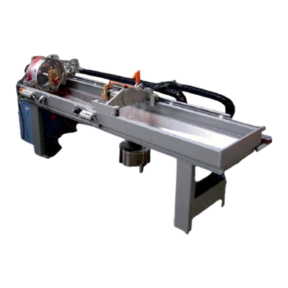
Page 6: Overview Of Main Components
1.3 OVERVIEW OF MAIN COMPONENTS 1.5 WORKING POSITION The Universal SW must be operated by one person. The main working position for normal operation is in the front of the machine, within the blackout booth. 1. Main operating console (control cabinet) 2. -
Page 7: Functions And Procedures
• Spraying of test liquid and magnetisation (spraying devices. time) • Magnetisation after spraying Contact the sales department at MAGNAFLUX GmbH for more information. Magnetisation is complete when the after-spray mag- netisation time has lapsed. Magnetic particles will have Workpiece clamping units collected in any cracks, making them clearly visible. - Page 8 NOTE: For this type of magnetisation, you need an additional magnetising mandrel. Please contact the The magnetising current is displayed on gauge on the sales department of Magnaflux GmbH. control cabinet in kAW, as the product of the current and the number of turns of the coil.
-
Page 9: Current Flow Control
For more information, • internal - magnetisation current is regulated against please contact MAGNAFLUX GmbH. zero along an exponential function to base e. Demagnetisation is performed immediately after DIN EN ISO 9934-1 (formerly DIN 54130) deals with magnetisation in the crack detection machine. -
Page 10: Spraying The Workpiece
Electronic demagnetising works according to the following principle: • The workpiece is magnetised with the set magnet- ising current during the magnetising cycle. • After rinsing and demagnetisation, the magnetising current is gradually reduced along an e-function until it is zero. OPTION: The hand-held shower spray system has an integrated push-button to activate the magnetising current and the test liquid spraying at the same time. -
Page 11: Test Liquid System
Spraying with large surface shower WARNING - FIRE HAZARD - Oil-based test liquids are highly flammable. Use As an option, a large surface shower can be installed only flame-retardant test liquids with a It will enable you to spray the workpiece [2] com- flash point >... -
Page 12: Pneumatic Maintenance Unit
2.10 PNEUMATIC MAINTENANCE UNIT 2.12 VISUAL INSPECTION Visually inspection is the most commonly used form of evaluating a workpiece. The operator visually inspects the workpiece, either while it is in the machine, or at a specially designed inspection station. By using fluorescent test liquids and UV lights you can easily spot test liquid accumulations which indicate cracks or other flaws in the workpiece. -
Page 13: Overview Of Controls
3. OVERVIEW OF CONTROLS 3.3 MAIN OPERATING CONSOLE NOTE: as an alternative to the controls described be- low, the Universal SW can be equipped with a T-Code Touch Panel. See separate instructions for how to use the T-Code system. 1. Main operating console (control cabinet) 2. -
Page 14: Emergency Stop Button
Operating elements of the magnetising circuits Selector switch for demagnetising Function: switches on/off the demagnetising in auto- matic mode Position 0: demagnetising off Position 1: demagnetising on Switch/speed controller for extraction fan (option) Function: switches on/off the extractor fan in the black- out booth, and adjusts its speed Position 0: extractor fan off Position 1: extractor fan on... -
Page 15: Right Operating Panel
4. GENERAL SAFETY INFORMATION Push-button: Magnetising Function: turns on the magnetisation as long as the 4.1 HAZARDS WHEN USING THE MACHINE button remains pressed. Prerequisite: workpiece clamped WARNING: This manual must be kept with the machine and must be Push-button: Demagnetising freely accessible for operating and maintenance personnel at all times. -
Page 16: Magnetic Fields In The Workplace
The basis for safe handling and trouble-free operation The operator of the machine is required to identify, of this machine is the knowledge of the safety and user document and mark areas of increased exposure. information in this manual. S/he must ensure that: •... -
Page 17: Training
• The machine must only be installed on a firm, not permitted without the written agreement of the level surface. manufacturer, Magnaflux GmbH. If you want to make • Comply with relevant local regulations for work any changes, please contact Magnaflux GmbH first. -
Page 18: Transport In Original Packaging
5.3 TRANSPORT IN ORIGINAL PACKAGING Transport with a forklift Procedure: The machine will be delivered on a pallet, a transport 1. Determine the transport route and remove any base or in a crate, and should be transported in this potential obstacles. condition as close as possible to the installation site 2. -
Page 19: Installation
6. INSTALLATION Transporting the control cabinet Only necessary if the control cabinet is not fixed to the machine. 6.1 SET UP THE MACHINE Procedure: CAUTION: Insufficient ventilation of controls, motors and transformers can 1. Check eyelets are securely fixed in place. lead to overheating. -
Page 20: Connect The Test Liquid Pump
7. COMMISSIONING Compressed air supply For the supply of compressed air, the Universal SW Before starting up the machine, complete the following requires a pneumatic connection with 6 bar and hose tasks: coupling NW 7.2. • Check power supply. The compressed air connection is located on the •... -
Page 21: Preparing For Operation
8. PREPARING FOR OPERATION Procedure: 1. Move the machine to its home position. 8.1 FILL WITH TEST LIQUID 2. Remove all workpieces from the machine. 3. Turn off the machine and secure it against being Before starting the machine, fill the test liquid tank with inadvertently switched on. -
Page 22: Adjust Workpiece Support On The Sleeve
8.5 ADJUST WORKPIECE SUPPORT ON THE 8.6 REFIT THE THREADING CONDUCTOR SLEEVE OR ROLLER BLOCK (OPTION) CAUTION: Heavy magnetisation Depending on the size and shape of the workpiece mandrel can cause injury to hands and ends, different supports may be required. fingers. -
Page 23: Change The Magnetising Coil
Depending on the dimensions and characteristics of the workpiece, different magnetisation coils may be required. Threading conductor with test liquid nozzle (option) 1. Clamping levers at the current bars (optional hexagonal screws) 1. Left or right magnetisation sleeve 2. Connecting nut to test liquid pipe 2. -
Page 24: Set Magnetising Parameters
9. OPERATION 8.8 SET MAGNETISATION PARAMETERS Set the magnetisation parameters with the controls on 9.1 SAFETY INFORMATION the control cabinet. Ensure that the field strength in the workpiece is sufficient for the inspection task. Check CAUTION: The Universal SW must the settings and crack detection function using a only be operated by trained personnel. -
Page 25: Initial Position Of The Machine
Turning the machine on after an emergency 9.4 MANUAL MODE WARNING: Before switching the 1. Select manual mode by setting the mode selector machine on again after an emergency switch to position 0. stop, determine and eliminate the 2. Insert a workpiece. cause of the stop. - Page 26 Inspection process without magnetising coil (circular magnetisation) The operation of the clamping device depends on the configuration of the machine and on the length of the clamping stroke: • Clamping stroke < 7 mm: Footswitch (left process in diagram below) or push-button Clamp (right process below) •...
- Page 27 Inspection process without magnetising coil WARNING: Heavy workpieces can fall (circular magnetisation) - continued from their position and cause serious personal injury and property damage. Prerequisites • Workpiece is inserted • Place the workpiece gently into position to avoid • The machine is in the initial position. damage.
- Page 28 Inspection process with manually movable magnetising coil (longitudinal magnetisation) The operation of the clamping device depends on the configuration of the machine and on the length of the clamping stroke: • Clamping stroke < 7 mm: Footswitch (left process in diagram below) or push-button Clamp (right process below) •...
- Page 29 Inspection process with manually movable Before releasing the sleeves in manual or automatic mode without a loader, the workpiece must be secured magnetising coil (longitudinal magnetisation) to a suspension device (crane, forklift). continued Prerequisites WARNING: Heavy workpieces can fall • Workpiece is inserted from their position and cause serious personal injury and property damage.
- Page 30 Inspection process with a motor-driven magnetising coil (longitudinal magnetisation) The operation of the clamping device depends on the configuration of the machine and on the length of the clamping stroke: • Clamping stroke < 7 mm: Footswitch (left process in diagram below) or push-button Clamp (right process below) •...
-
Page 31: Cleaning The Machine
Inspection process with a motor-driven WARNING: Heavy workpieces can fall magnetising coil (longitudinal magnetisation) from their position and cause serious continued personal injury and property damage. Prerequisites • Place the workpiece gently into position to avoid • Workpiece is inserted damage. -
Page 32: Dealing With Faults
• Check current regulation by repeating the chain. magnetisation process with an already-tested) workpiece. Interval: 400 hours • Call Magnaflux GmbH customer service. Disconnect the high current conducting cables. Clean the contact points until they are shiny and apply a thin layer of contact grease. -
Page 33: Inspection Procedures
10.3 INSPECTION PROCEDURES Measuring magnetising field strength The intensity and characteristics of the magnetic field are important parameters for magnetic particle inspec- tion. Always check the magnetisation when setting up the machine for new workpieces. The FSM-2 is used to measure tangential magnetic field strength. - Page 34 Checking UV light intensity The detection of cracks in workpieces can be consid- erably increased by using a fluorescent test liquid and UV light. The intensity of illumination plays a significant role in the process. The light intensity should be approximately 1000 µW/ cm², although deviations from this value are possible.
-
Page 35: Procedures For Routine Maintenance
10.4 PROCEDURES FOR ROUTINE MAINTENANCE Filling the proportional oiler with oil Cleaning the test liquid tank CAUTION Spilled oil can lead to injury due to When spraying a workpiece with test liquid, dirt particles slipping. get washed off and accumulate in the test liquid tank. - Page 36 Loosen the two screws on the left and right side turer, Magnaflux GmbH. The manufacturer accepts of the contact plate, and remove the copper pad no liability for damages caused by the use of non- and clamping parts.
- Page 37 Cleaning the high current connection contacts 9. Apply a thin coat of contact grease to the rest of the shaft Regularly clean all contact points (current transfer 10. If present: grease the coil's drive chain using a points) between the high current transformer, the brush.
-
Page 38: Procedures For Repair
10.5 PROCEDURES FOR REPAIR Checking the flange wheels, clamping levers and ball bearings Safety clutch 4. Pressure disc with 12 markings 5. Adjustment nut 6. Locking screw Flange wheels and ball bearings at the sleeve carriage 1. Flange wheels 2. Clamping lever Procedure 1. - Page 39 Prerequisites Replacing the coil guides Auxiliary spare parts: see spare part list CAUTION: • Flange wheels, wheel bolts, ball bearings Motor-driven magnetisation coil can • Upper and lower clamping lever crush hands. Procedure 1. Unclamp the quills and remove the workpiece from the machine.
-
Page 40: Decommissioning And Disposal
• Rechargeable batteries, dry batteries, button cells • Paints, lacquers, adhesives • Chemicals (e.g. solvents, cleaning agents etc.) • Fluorescent tubes, UV lamps, • Waste oil and oil filters Please direct any other questions to Magnaflux GmbH. - Page 41 Bahnhofstr 94-98, 73457 Essingen, Deutschland Telephone: +49 (0) 7365 81-0 Fax: +49 (0) 7365 81-449 Email: sales.de@magnaflux.com Web: eu.magnaflux.com/de Faraday Road, South Dorcan Industrial Estate, Swindon, SN3 5HE, UK Telephone: + 44 (0)1793 524566 Fax: +44 (0)1793 490459 Email: sales.eu@magnaflux.com...
Need help?
Do you have a question about the Universal SW Series and is the answer not in the manual?
Questions and answers