Advertisement
Quick Links
Advertisement

Subscribe to Our Youtube Channel
Related Manuals for BH FITNESS BS1299


Summary of Contents for BH FITNESS BS1299
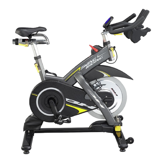
- Page 1 BS999 BS1299 USER MANUAL...
- Page 4 $V V HP EO \' U DZL QJ STEP 1 Attach the front foot tube (14) to the frame using the spring washers (7) and bolts (45) from the bottom of the tube to up to tighten front foot tube on frame, then attach the rear foot tube (11) to the frame using the nuts (6), spring washers (7) and fixing bolts (8) to tighten rear foot tube on frame. ...
- Page 5 STEP 2 Attach the handlebar post (21) inserting into the head tube on the frame. Using release lever (2) to adjusts and tightens the height in proper position. Then attached handlebar slider (20) on the handlebar post (21), use release lever (17) to adjust and tighten the handlebar in proper position. Secure fixed the monitor (62) to the console’s bracket with the screw from the back of the console. Connect curve cable (64) into monitor rear part. STEP 3 Insert the seat post (39) into the frame’s seat tube. Attach the saddle (1) into seat slider (38). ...
- Page 6 STEP 5 Adjust the exercise resistance on the spinning bike using the resistance knob (22) to loosen (‐) or tighten (+). The flywheel should rotate freely without resistance when you loosen (‐) the brake system fully. More experienced riders may wish to increase the overall resistance by tightening (+) the brake system.
- Page 7 ※ To switch fixed mode and swing riding mode, method as below – The operating by parts #80 switch system. fixed mode swing riding mode Pull the switch system (80) toward Move forward the switch system to the rider. (80) to pass the stopper position When you hear the "click" sound, (no sound). it will switch to swing riding mode. It’s the fixed mode.
- Page 8 Instruction : Handlebar and seat adjustment. It is important that the handlebar and seat are set at the correct height for your body. Ask your instructor for assistance. Adjusting the handlebar height-Undo the release lever that is located where the handlebar post fits into the frame.
- Page 9 ([SO RGHG ' U DZL QJ...
- Page 10 3DUW O L V W Name Unit No. Name Unit Saddle PC 43 End cap for seat slider Release lever PC 44 Rubber sleeve Outer chain guard PC 45 Foot tube bolt Crank arm set SET 47 Fixed bolt for release lever Crank bolt PC 48 Flywheel (complete)
- Page 11 Name Unit No. Name Unit Belt PC 87 Washer ø 6 Bottle Screw PC 101 Washer ø 14 PC 102 Flywheel adjuster bolt Nuts w/washers, fixed plate, bolts Front fixed plate for fender PC 103 Bolt M5 PC 104 C clip ø 14 Screw for sensor cover PC 105 Pin w/bushings...
- Page 12 0 DL QW HQDQFH&KDUW Annuall DESCRIPTION Daily Weekly Monthly Quarterly Keep machine clean: Wipe machine down with clean & dry fabric to clear dirt & sweat. Wipe Anti-rusty cream or similar on the seat post set, handlebar set Visual check Check security of handle bar post &...
- Page 13 4) Make sure flywheel keeps parallel with frame. And two sides distance between flywheel and magnet must be the same. 5) After finished the above steps, screw the nut by both sides. Make sure the nut is tighten and fixedly. ※...
- Page 14 &RQV RO H Console (with Battery) RPM / Avg. RPM Window Heart Rate / Avg. Heart Rate KCAL / WATT Window Avg. WATT Window LOAD Window DIST / TIME Window Window Display RPM, HEART RATE, KCAL,WATT, DIST, TIME , LOAD AVG.
- Page 16 BH Asia Ltd. No. 80, Zhongshan Rd., Daya Dist., Taichung City 42841, Taiwan Tel: +886 4 2560 9200 Fax: +886 4 2560 9280 Email: info@bhasia.com.tw...
Need help?
Do you have a question about the BS1299 and is the answer not in the manual?
Questions and answers