Table of Contents
Advertisement
Quick Links
ГК Атлант Инжиниринг – официальный представитель в РФ и СНГ
+7(495)109-02-08 sales@bbrc.ru www.bbrc.ru
tM Series DIO
Warranty
All products manufactured by ICP DAS are under
warranty regarding defective materials for a period of one
year from the date of delivery to the original purchaser.
Warning
ICP DAS assumes no liability for damages resulting
from the use of this product. ICP DAS reserves the right to
change this manual at any time without notification. The
information furnished by ICP DAS is believed to be accurate
and reliable. However, no responsibility is assumed by ICP
DAS for its use, or for any infringements of patents or other
rights of third parties resulting from its use.
Copyright
Copyright 2012 ICP DAS. All rights reserved.
Trademark
The names used for identification only may be registered
trademarks of their respective companies.
tM Series DIO User Manual, Rev: A1.3 7PH-013-A13
User Manual
Date: 2012/05/14
1
Advertisement
Table of Contents

Related Manuals for ICP DAS USA tM Series


Summary of Contents for ICP DAS USA tM Series
- Page 1 Copyright Copyright 2012 ICP DAS. All rights reserved. Trademark The names used for identification only may be registered trademarks of their respective companies. Date: 2012/05/14 tM Series DIO User Manual, Rev: A1.3 7PH-013-A13...
-
Page 2: Table Of Contents
1.9 Configuration Tables............. 29 1.10 DIO Active States ............... 32 1.11 Mounting ................33 1.11.1 Din-Rail Mounting ............. 33 1.12 Technical Support ............... 35 2. DCON Protocol................36 2.1 %AANNTTCCFF ..............39 2.2 #**..................42 tM Series DIO User Manual, Rev: A1.3 7PH-013-A13... - Page 3 3.2 02 (0x02) Read Discrete Inputs........... 107 3.3 03 (0x03) Read Multiple Registers ........108 3.4 04 (0x04) Read Multiple Input Registers ......109 3.5 05 (0x05) Write Single Coils ..........110 tM Series DIO User Manual, Rev: A1.3 7PH-013-A13...
- Page 4 A.5 Safe Value and Power-on Value of Digital Output .... 138 A.6 Latched Digital Input............139 A.7 DN Module................. 140 A.7.1 DN-SSR4..............141 A.7.2 DN-PR4..............142 A.7.3 RM-104, RM-108, and RM-116........ 143 A.7.4 RM-204, RM-208, RM-216 ........144 tM Series DIO User Manual, Rev: A1.3 7PH-013-A13...
-
Page 5: Introduction
ГК Атлант Инжиниринг – официальный представитель в РФ и СНГ +7(495)109-02-08 sales@bbrc.ru www.bbrc.ru 1. Introduction The tM series is a family of network data acquisition and control modules, providing digital input/output and counter functions. The modules can be remotely controlled using a set of commands, which we call the DCON protocol, or the standard Modbus protocol. -
Page 6: More Information
The module with digital inputs provides the latched digital inputs, please refer to Section A.6 Latched Digital Input for details. For details of the I/O extension modules, please refer to Section A.7 DN Module. tM Series DIO User Manual, Rev: A1.3 7PH-013-A13... -
Page 7: Terminal Assignment
ГК Атлант Инжиниринг – официальный представитель в РФ и СНГ +7(495)109-02-08 sales@bbrc.ru www.bbrc.ru 1.2 Terminal Assignment tM Series DIO User Manual, Rev: A1.3 7PH-013-A13... - Page 8 ГК Атлант Инжиниринг – официальный представитель в РФ и СНГ +7(495)109-02-08 sales@bbrc.ru www.bbrc.ru tM Series DIO User Manual, Rev: A1.3 7PH-013-A13...
- Page 9 ГК Атлант Инжиниринг – официальный представитель в РФ и СНГ +7(495)109-02-08 sales@bbrc.ru www.bbrc.ru tM Series DIO User Manual, Rev: A1.3 7PH-013-A13...
- Page 10 ГК Атлант Инжиниринг – официальный представитель в РФ и СНГ +7(495)109-02-08 sales@bbrc.ru www.bbrc.ru tM Series DIO User Manual, Rev: A1.3 7PH-013-A13...
- Page 11 ГК Атлант Инжиниринг – официальный представитель в РФ и СНГ +7(495)109-02-08 sales@bbrc.ru www.bbrc.ru tM Series DIO User Manual, Rev: A1.3 7PH-013-A13...
- Page 12 ГК Атлант Инжиниринг – официальный представитель в РФ и СНГ +7(495)109-02-08 sales@bbrc.ru www.bbrc.ru tM-P3POR3 tM Series DIO User Manual, Rev: A1.3 7PH-013-A13...
- Page 13 ГК Атлант Инжиниринг – официальный представитель в РФ и СНГ +7(495)109-02-08 sales@bbrc.ru www.bbrc.ru tM-R5 tM Series DIO User Manual, Rev: A1.3 7PH-013-A13...
-
Page 14: Specifications
Yes, Programmable Yes, Programmable Yes, Programmable Power Requirements Reverse Polarity Protection Powered from Terminal Yes, 10 ~ 30 VDC Block Consumption 0.5 W max 0.5 W max 0.8 W max 0.4 W max tM Series DIO User Manual, Rev: A1.3 7PH-013-A13... - Page 15 Max. Input Frequency 100 Hz Counters Min. Pulse Width 5 ms 70 VDC Over-voltage Protection Power Requirements Reverse Polarity Protection Powered from Terminal Block Yes, 10 ~ 30 VDC Consumption 0.4 W max tM Series DIO User Manual, Rev: A1.3 7PH-013-A13...
- Page 16 100 Hz Counters Min. Pulse Width 5 ms 70 VDC Over-voltage Protection Power Requirements Reverse Polarity Protection Powered from Terminal Block Yes, 10 ~ 30 VDC Consumption 0.6 W max 1.0 W max tM Series DIO User Manual, Rev: A1.3 7PH-013-A13...
-
Page 17: System Specifications
Dimensions (W x L x H) 52 mm x 27 mm x 98 mm Installation DIN-Rail Mounting Environment Operating Temperature -25 ~ +75 °C Storage Temperature -30 ~ +75 °C Humidity 10 ~ 95% RH, non-condensing tM Series DIO User Manual, Rev: A1.3 7PH-013-A13... -
Page 18: Block Diagrams
ГК Атлант Инжиниринг – официальный представитель в РФ и СНГ +7(495)109-02-08 sales@bbrc.ru www.bbrc.ru 1.4 Block Diagrams 1.4.1 Block Diagram for the tM-C8 1.4.2 Block Diagram for the tM-P8 tM Series DIO User Manual, Rev: A1.3 7PH-013-A13... -
Page 19: Block Diagram For The Tm-P4A4
ГК Атлант Инжиниринг – официальный представитель в РФ и СНГ +7(495)109-02-08 sales@bbrc.ru www.bbrc.ru 1.4.3 Block Diagram for the tM-P4A4 1.4.4 Block Diagram for the tM-P4C4 tM Series DIO User Manual, Rev: A1.3 7PH-013-A13... -
Page 20: Block Diagram For The Tm-P3Por3
ГК Атлант Инжиниринг – официальный представитель в РФ и СНГ +7(495)109-02-08 sales@bbrc.ru www.bbrc.ru 1.4.5 Block Diagram for the tM-P3POR3 1.4.6 Block Diagram for the tM-P3R3 tM Series DIO User Manual, Rev: A1.3 7PH-013-A13... -
Page 21: Block Diagram For The Tm-R5
ГК Атлант Инжиниринг – официальный представитель в РФ и СНГ +7(495)109-02-08 sales@bbrc.ru www.bbrc.ru 1.4.7 Block Diagram for the tM-R5 tM Series DIO User Manual, Rev: A1.3 7PH-013-A13... -
Page 22: Dimensions
ГК Атлант Инжиниринг – официальный представитель в РФ и СНГ +7(495)109-02-08 sales@bbrc.ru www.bbrc.ru 1.5 Dimensions tM Series DIO User Manual, Rev: A1.3 7PH-013-A13... -
Page 23: Wiring
ГК Атлант Инжиниринг – официальный представитель в РФ и СНГ +7(495)109-02-08 sales@bbrc.ru www.bbrc.ru 1.6 Wiring 1.6.1 tM-C8 wiring 1.6.2 tM-P8 wiring 1.6.3 tM-P4A4 wiring tM Series DIO User Manual, Rev: A1.3 7PH-013-A13... -
Page 24: Tm-P4C4 Wiring
ГК Атлант Инжиниринг – официальный представитель в РФ и СНГ +7(495)109-02-08 sales@bbrc.ru www.bbrc.ru 1.6.4 tM-P4C4 wiring 1.6.5 tM-P3POR3 wiring tM Series DIO User Manual, Rev: A1.3 7PH-013-A13... -
Page 25: Tm-P3R3 Wiring
ГК Атлант Инжиниринг – официальный представитель в РФ и СНГ +7(495)109-02-08 sales@bbrc.ru www.bbrc.ru 1.6.6 tM-P3R3 wiring 1.6.7 tM-R5 wiring tM Series DIO User Manual, Rev: A1.3 7PH-013-A13... -
Page 26: Wiring Recommendations
Strip the wire to a length of 7±0.5mm. Use a crimp terminal for wiring. Avoid high-voltage cables and power equipment as much as possible. For RS-485 communication, use insulated and twisted pair 24 AWG wire, e.g. Belden 9841. tM Series DIO User Manual, Rev: A1.3 7PH-013-A13... -
Page 27: Quick Start
ГК Атлант Инжиниринг – официальный представитель в РФ и СНГ +7(495)109-02-08 sales@bbrc.ru www.bbrc.ru 1.7 Quick Start Please refer to the Quick Start Guide for tM series DIO. tM Series DIO User Manual, Rev: A1.3 7PH-013-A13... -
Page 28: Default Settings
+7(495)109-02-08 sales@bbrc.ru www.bbrc.ru 1.8 Default Settings Default settings for the tM DIO modules are as follows: 。 Protocol: Modbus RTU 。 Module Address: 01 。 DIO Type: Type 40 。 Baud Rate: 9600 bps tM Series DIO User Manual, Rev: A1.3 7PH-013-A13... -
Page 29: Configuration Tables
2: eight data bits, even parity, and one stop bit 3: eight data bits, odd parity, and one stop bit Type Setting (TT) For tM modules, the type code is fixed to 40. tM Series DIO User Manual, Rev: A1.3 7PH-013-A13... - Page 30 0: The counter is updated when there is a falling edge in the input signal. 1: The counter is updated when there is a rising edge in the input signal. Note: The reserved bits should be zero. tM Series DIO User Manual, Rev: A1.3 7PH-013-A13...
- Page 31 DI1 ~ DI3 00 ~ 07 tM-P3R3 DO1 ~ DO3 00 ~ 07 DI1 ~ DI3 00 ~ 07 tM-C8 DO1 ~ DO8 00 ~ FF tM-R5 DO1 ~ DO5 00 ~ 1F tM Series DIO User Manual, Rev: A1.3 7PH-013-A13...
-
Page 32: Dio Active States
The DIO read value of the tM modules are as follows: Inactive Active tM-P8 tM-P4C4 tM-P4A4 tM-P3POR3 tM-P3R3 tM-C8 tM-R5 ON means the DIO read value is 1. OFF means the DIO read value is 0. tM Series DIO User Manual, Rev: A1.3 7PH-013-A13... -
Page 33: Mounting
The three new DIN rail models are as follows. Part number Max. number of modules Dimensions DRS-360 360mm x 35mm tM Series DIO User Manual, Rev: A1.3 7PH-013-A13... - Page 34 Part number Max. number of modules Dimensions DRS-125 125mm x 35mm Note: It is recommended that a 16 – 14 AWG wire is used to connect the DIN rail to the earth ground. tM Series DIO User Manual, Rev: A1.3 7PH-013-A13...
-
Page 35: Technical Support
7. Any comments and suggestions related to the problem are welcome. ICP DAS will reply to your request by email within three business days. tM Series DIO User Manual, Rev: A1.3 7PH-013-A13... -
Page 36: Dcon Protocol
Character Address A 2-character checksum which is present when CHKSUM the checksum setting is enabled. See Sections 1.9 (Data Format Setting) and 2.1 for details. End of command character, carriage return (0x0D) tM Series DIO User Manual, Rev: A1.3 7PH-013-A13... - Page 37 “!”+”0”+”1”+”2”+”0”+”0”+”6”+”0”+”0” = 21h+30h+31h+32h+30h+30h+36h+30h+30h = 1AAh 2. Therefore the checksum is AAh, and so CHKSUM = “AA” 3. The response string with the checksum = !01200600AA(CR) Note: All characters should be in upper case. tM Series DIO User Manual, Rev: A1.3 7PH-013-A13...
- Page 38 Reads the Status 2.26 ~AA1 Resets the Status 2.27 ~AA2 !AAVV Reads the Timeout Settings 2.28 ~AA3EVV Sets the Timeout Settings 2.29 ~AA4V !AA(Data) Reads the PowerOn/Safe Value 2.30 ~AA5V Sets the PowerOn/Safe Value tM Series DIO User Manual, Rev: A1.3 7PH-013-A13...
-
Page 39: Aannttccff
For the module with frame ground, this is achieved by moving the rear slide switch to the INIT position. See Section A.1 for details. tM Series DIO User Manual, Rev: A1.3 7PH-013-A13... - Page 40 INIT* mode. Command: %0101200A00 Response: !01 Changes the Baud Rate of module 01 to 115200bps and the module is in INIT* mode. The module returns a valid response. tM Series DIO User Manual, Rev: A1.3 7PH-013-A13...
- Page 41 Changes to the address and counter update direction settings take effect immediately after a valid command is received. Changes to the Baud Rate and checksum settings take effect on the next power-on reset. tM Series DIO User Manual, Rev: A1.3 7PH-013-A13...
- Page 42 0, which means that it is NOT the first time the synchronized data has been read after the previous #** command. Related Commands: Section 2.11 $AA4 tM Series DIO User Manual, Rev: A1.3 7PH-013-A13...
-
Page 43: Aa00(Data)
There will be no response if the command syntax is incorrect, there is a communication error, or there is no module with the specified address. tM Series DIO User Manual, Rev: A1.3 7PH-013-A13... - Page 44 #AABcDD, Section 2.13 $AA6, Section 2.21 @AA Related Topics: Section 1.10 DIO Active States Notes: 1. This command is only applicable to the modules with digital output channels. 2. This command is the same as the #AA0A(Data) command. tM Series DIO User Manual, Rev: A1.3 7PH-013-A13...
-
Page 45: Aa0A(Data)
There will be no response if the command syntax is incorrect, there is a communication error, or there is no module with the specified address. tM Series DIO User Manual, Rev: A1.3 7PH-013-A13... - Page 46 #AABcDD, Section 2.13 $AA6, Section 2.21 @AA Related Topics: Section 1.10 DIO Active States Notes: 1. This command is only applicable to the modules with digital output channels. 2. This command is the same as the #AA00(Data) command. tM Series DIO User Manual, Rev: A1.3 7PH-013-A13...
-
Page 47: Aa0B(Data)
There will be no response if the command syntax is incorrect, there is a communication error, or there is no module with the specified address. tM Series DIO User Manual, Rev: A1.3 7PH-013-A13... - Page 48 #AABcDD, Section 2.13 $AA6, Section 2.21 @AA Related Topics: Section 1.10 DIO Active States Notes: This command is only applicable to the modules with the number of digital output channels larger than eight. tM Series DIO User Manual, Rev: A1.3 7PH-013-A13...
-
Page 49: Aa1Cdd
There will be no response if the command syntax is incorrect, there is a communication error, or there is no module with the specified address. tM Series DIO User Manual, Rev: A1.3 7PH-013-A13... - Page 50 #AABcDD, Section 2.13 $AA6, Section 2.21 @AA Related Topics: Section 1.10 DIO Active States Notes: 1. This command is only applicable to the modules with digital output channels. 2. This command is the same as the #AAAcDD command. tM Series DIO User Manual, Rev: A1.3 7PH-013-A13...
-
Page 51: Aaacdd
There will be no response if the command syntax is incorrect, there is a communication error, or there is no module with the specified address. tM Series DIO User Manual, Rev: A1.3 7PH-013-A13... - Page 52 #AABcDD, Section 2.13 $AA6, Section 2.21 @AA Related Topics: Section 1.10 DIO Active States Notes: 1. This command is only applicable to the modules with digital output channels. 2. This command is the same as the #AA1cDD command. tM Series DIO User Manual, Rev: A1.3 7PH-013-A13...
-
Page 53: Aabcdd
Delimiter character for an invalid command Delimiter character for an ignored command. A host watchdog timeout has occurred, the digital output ports are set to safe value, and the digital output value that was sent is ignored. tM Series DIO User Manual, Rev: A1.3 7PH-013-A13... - Page 54 #AAAcDD, Section 2.13 $AA6, Section 2.21 @AA Related Topics: Section 1.10 DIO Active States Notes: This command is only applicable to the modules with the number of digital output channels larger than eight. tM Series DIO User Manual, Rev: A1.3 7PH-013-A13...
-
Page 55: Aan
Address of the responding module (00 to FF) There will be no response if the command syntax is incorrect, there is a communication error, or there is no module with the specified address. tM Series DIO User Manual, Rev: A1.3 7PH-013-A13... - Page 56 Reads data from channel 9 of module 02. An error is returned because channel 9 is invalid. Related Commands: Section 2.15 $AACN Notes: This command is only applicable to the module with digital inputs. tM Series DIO User Manual, Rev: A1.3 7PH-013-A13...
-
Page 57: Aa2
Section 1.9 for details. There will be no response if the command syntax is incorrect, there is a communication error, or there is no module with the specified address. tM Series DIO User Manual, Rev: A1.3 7PH-013-A13... - Page 58 ГК Атлант Инжиниринг – официальный представитель в РФ и СНГ +7(495)109-02-08 sales@bbrc.ru www.bbrc.ru Examples: Command: $012 Response: !01400600 Reads the configuration of module 01. Related Commands: Section 2.1 %AANNTTCCFF Related Topics: Section 1.9 Configuration Tables tM Series DIO User Manual, Rev: A1.3 7PH-013-A13...
-
Page 59: Aa4
Synchronized data. See Section 1.9 for the data format. There will be no response if the command syntax is incorrect, there is a communication error, or there is no module with the specified address. tM Series DIO User Manual, Rev: A1.3 7PH-013-A13... - Page 60 Reads the synchronized data for module 01. The module returns the synchronized data and sets the status byte to 0 to indicate that the synchronized data has been read. Related Commands: Section 2.2 #** tM Series DIO User Manual, Rev: A1.3 7PH-013-A13...
-
Page 61: Aa5
$AA5 command was sent. There will be no response if the command syntax is incorrect, there is a communication error, or there is no module with the specified address. tM Series DIO User Manual, Rev: A1.3 7PH-013-A13... - Page 62 Response: !010 Reads the reset status of module 01. The response shows that there has been no module reset since the last $AA5 command was sent. Related Topics: Section A.4 Reset Status tM Series DIO User Manual, Rev: A1.3 7PH-013-A13...
-
Page 63: Aa6
00. See Section 1.9 for details. There will be no response if the command syntax is incorrect, there is a communication error, or there is no module with the specified address. tM Series DIO User Manual, Rev: A1.3 7PH-013-A13... - Page 64 01 and returns 0F0000h, which denotes that RL1, RL2, RL3 and RL4 are on and IN1, IN2, IN3 and IN4 are off. Related Commands: Section 2.21 @AA Related Topics: Section 1.9 Configuration Tables tM Series DIO User Manual, Rev: A1.3 7PH-013-A13...
-
Page 65: Aac
Address of the responding module (00 to FF) There will be no response if the command syntax is incorrect, there is a communication error, or there is no module with the specified address. tM Series DIO User Manual, Rev: A1.3 7PH-013-A13... - Page 66 Section 2.17 $AALS Notes: 1. This command is only applicable to the modules with digital input channels. 2. Both the status of the low and high latched digital input channels are cleared. tM Series DIO User Manual, Rev: A1.3 7PH-013-A13...
-
Page 67: Aacn
Address of the responding module (00 to FF) There will be no response if the command syntax is incorrect, there is a communication error, or there is no module with the specified address. tM Series DIO User Manual, Rev: A1.3 7PH-013-A13... - Page 68 Reads counter data from channel 2 of module 03 and the returned counter value is 3. Related Commands: Section 2.9 #AAN Notes: This command is only applicable to the module with digital inputs. tM Series DIO User Manual, Rev: A1.3 7PH-013-A13...
-
Page 69: Aaf
Reads the firmware version of module 01, and shows that it is version A2.0. Command: $02F Response: !02B1.1 Reads the firmware version of module 02, and shows that it is version B1.1. tM Series DIO User Manual, Rev: A1.3 7PH-013-A13... -
Page 70: Aals
00. See Section 1.9 for details. There will be no response if the command syntax is incorrect, there is a communication error, or there is no module with the specified address. tM Series DIO User Manual, Rev: A1.3 7PH-013-A13... - Page 71 01 and returns 0000. Related Commands: Section 2.14 $AAC Related Topics: Section 1.9 Configuration Tables Notes: This command is only applicable to the modules with digital input channels. tM Series DIO User Manual, Rev: A1.3 7PH-013-A13...
-
Page 72: Aam
Examples: Command: $01M Response: !01tP4C4 Reads the module name of module 01 and returns the name “tP4C4”. Related Commands: Section 2.23 ~AAO(Name) tM Series DIO User Manual, Rev: A1.3 7PH-013-A13... -
Page 73: Aap
3: the protocol set in the EEPROM is Modbus ASCII There will be no response if the command syntax is incorrect, there is a communication error, or there is no module with the specified address. tM Series DIO User Manual, Rev: A1.3 7PH-013-A13... - Page 74 10 meaning that it supports both the DCON and Modbus RTU protocols and the protocol that will be used at the next power-on reset is DCON. Related Commands: Section 2.20 $AAPN tM Series DIO User Manual, Rev: A1.3 7PH-013-A13...
-
Page 75: Aapn
Address of the responding module (00 to FF) There will be no response if the command syntax is incorrect, there is a communication error, or there is no module with the specified address. tM Series DIO User Manual, Rev: A1.3 7PH-013-A13... - Page 76 RTU and returns an invalid response because the module is not in INIT mode. Command: $01P1 Response: !01 Sets the communication protocol of module 01 to Modbus RTU and returns a valid response. Related Commands: Section 2.19 $AAP tM Series DIO User Manual, Rev: A1.3 7PH-013-A13...
- Page 77 See Section 1.9 for details. There will be no response if the command syntax is incorrect, there is a communication error, or there is no module with the specified address. tM Series DIO User Manual, Rev: A1.3 7PH-013-A13...
- Page 78 0F00h, which denotes that RL1, RL2, RL3 and RL4 are on and IN1, IN2, IN3 and IN4 are off. Related Commands: Section 2.13 $AA6 Related Topics: Section 1.9 Configuration Tables tM Series DIO User Manual, Rev: A1.3 7PH-013-A13...
-
Page 79: Aa(Data)
Delimiter character for an invalid command Delimiter character for an ignored command. A host watchdog timeout has occurred, the digital output ports are set to safe value, and the digital output value that was sent is ignored. tM Series DIO User Manual, Rev: A1.3 7PH-013-A13... - Page 80 Related Commands: Section 2.21 @AA Related Topics: Section 1.10 DIO Active States Notes: This command is only applicable to the modules with digital output channels. tM Series DIO User Manual, Rev: A1.3 7PH-013-A13...
-
Page 81: Aao(Name)
Address of the responding module (00 to FF) There will be no response if the command syntax is incorrect, there is a communication error, or there is no module with the specified address. tM Series DIO User Manual, Rev: A1.3 7PH-013-A13... - Page 82 Sets the name of module 01 to be “7050N” and returns a valid response. Command: $01M Response: !017050N Reads the name of module 01 and returns the name “7050N”. Related Commands: Section 2.18 $AAM tM Series DIO User Manual, Rev: A1.3 7PH-013-A13...
- Page 83 Sends a “Host OK” command to all modules. Related Commands: Section 2.25 ~AA0, Section 2.26 ~AA1, Section 2.27 ~AA2, Section 2.28 ~AA3EVV, Section 2.29 ~AA4V, Section 2.30 ~AA5V Related Topics: Section A.2 Dual Watchdog Operation tM Series DIO User Manual, Rev: A1.3 7PH-013-A13...
-
Page 84: Aa0
Bit 2: 1 indicates that a host watchdog timeout has occurred, and 0 indicates that no host watchdog timeout has occurred. The host watchdog status is stored in EEPROM and can only be reset by using the ~AA1 command. tM Series DIO User Manual, Rev: A1.3 7PH-013-A13... - Page 85 04, meaning that a host watchdog timeout has occurred. Related Commands: Section 2.24 ~**, Section 2.26 ~AA1, Section 2.27 ~AA2, Section 2.28 ~AA3EVV, Section 2.29 ~AA4V, Section 2.30 ~AA5V Related Topics: Section A.2 Dual Watchdog Operation tM Series DIO User Manual, Rev: A1.3 7PH-013-A13...
-
Page 86: Aa1
Address of the responding module (00 to FF) There will be no response if the command syntax is incorrect, there is a communication error, or there is no module with the specified address. tM Series DIO User Manual, Rev: A1.3 7PH-013-A13... - Page 87 Related Commands: Section 2.24 ~**, Section 2.25 ~AA0, Section 2.27 ~AA2, Section 2.28 ~AA3EVV, Section 2.29 ~AA4V, Section 2.30 ~AA5V Related Topics: Section A.2 Dual Watchdog Operation tM Series DIO User Manual, Rev: A1.3 7PH-013-A13...
-
Page 88: Aa2
0.1 seconds and FF denotes 25.5 seconds. There will be no response if the command syntax is incorrect, there is a communication error, or there is no module with the specified address. tM Series DIO User Manual, Rev: A1.3 7PH-013-A13... - Page 89 25.5 seconds. Related Commands: Section 2.24 ~**, Section 2.25 ~AA0, Section 2.26 ~AA1, Section 2.28 ~AA3EVV, Section 2.29 ~AA4V, Section 2.30 ~AA5V Related Topics: Section A.2 Dual Watchdog Operation tM Series DIO User Manual, Rev: A1.3 7PH-013-A13...
-
Page 90: Aa3Evv
Address of the responding module (00 to FF) There will be no response if the command syntax is incorrect, there is a communication error, or there is no module with the specified address. tM Series DIO User Manual, Rev: A1.3 7PH-013-A13... - Page 91 ~AA5V Related Topics: Section A.2 Dual Watchdog Operation Notes: When a host watchdog timeout occurs, the host watchdog is disabled. The ~AA3EVV command should be sent again to reenable the host watchdog. tM Series DIO User Manual, Rev: A1.3 7PH-013-A13...
-
Page 92: Aa4V
They are two hexadecimal digits followed by 00. There will be no response if the command syntax is incorrect, there is a communication error, or there is no module with the specified address. tM Series DIO User Manual, Rev: A1.3 7PH-013-A13... - Page 93 FF00. Related Commands: Section 2.30 ~AA5V Related Topics: Section 1.10 DIO Active States, Section A.2 Dual Watchdog Operation Notes: This command is only applicable to the modules with digital output channels. tM Series DIO User Manual, Rev: A1.3 7PH-013-A13...
-
Page 94: Aa5V
Address of the responding module (00 to FF) There will be no response if the command syntax is incorrect, there is a communication error, or there is no module with the specified address. tM Series DIO User Manual, Rev: A1.3 7PH-013-A13... - Page 95 5500, which denotes that the safe DO value is Related Commands: Section 2.29 ~AA4V Related Topics: Section A.2 Dual Watchdog Operation Notes: This command is only applicable to the modules with the digital output channels. tM Series DIO User Manual, Rev: A1.3 7PH-013-A13...
-
Page 96: Aad
0: input value 1 for non-signal or the low voltage; input value 0 for high voltage 1: input value 0 for non-signal or the low voltage; input value 1 for high voltage tM Series DIO User Manual, Rev: A1.3 7PH-013-A13... - Page 97 Examples: Command: ~01D Response: !0101 Reads the miscellaneous settings of module 01 and returns 01. Related Commands: Section 2.32 ~AADVV tM Series DIO User Manual, Rev: A1.3 7PH-013-A13...
-
Page 98: Aadvv
0: input value 1 for non-signal or the low voltage; input value 0 for high voltage 1: input value 0 for non-signal or the low voltage; input value 1 for high voltage tM Series DIO User Manual, Rev: A1.3 7PH-013-A13... - Page 99 Examples: Command: ~01D01 Response: !01 Sets the miscellaneous settings of module 01 to 01, and returns a valid response. Related Commands: Section 2.31 ~AAD tM Series DIO User Manual, Rev: A1.3 7PH-013-A13...
-
Page 100: Aard
1ms and 1E denotes 30ms. The max allowable value is 30 (1Eh). There will be no response if the command syntax is incorrect, there is a communication error, or there is no module with the specified address. tM Series DIO User Manual, Rev: A1.3 7PH-013-A13... - Page 101 Examples: Command: ~01RD Response: !0102 Reads the response delay time value of module 01 and returns 02, which denotes that the response delay time value is 2ms. Related Commands: Section 2.34 ~AARDVV tM Series DIO User Manual, Rev: A1.3 7PH-013-A13...
-
Page 102: Aardvv
Address of the responding module (00 to FF) There will be no response if the command syntax is incorrect, there is a communication error, or there is no module with the specified address. tM Series DIO User Manual, Rev: A1.3 7PH-013-A13... - Page 103 Command: ~01RD Response: !0106 Reads the response delay time value of module 01. The module returns 06, which denotes that the response delay time value is 6ms. Related Commands: Section 2.33 ~AARD tM Series DIO User Manual, Rev: A1.3 7PH-013-A13...
-
Page 104: Modbus Rtu Protocol
Modicon controllers. Detailed information can be found at http://www.modicon.com/techpubs/toc7.html. You can also visit http://www.modbus.org to find more valuable information. tM series modules support the Modbus RTU protocol. The communication Baud Rates range from 1200bps to 115200bps. The following Modbus functions are supported. Description Function code... -
Page 105: 0X01) Read Coils
Error Response Address 1 Byte 1 ~ 247 Function code 1 Byte 0x81 Exception code 1 Byte Refer to the Modbus standard for more details. tM Series DIO User Manual, Rev: A1.3 7PH-013-A13... - Page 106 0x0040~0x0047 for DO Latch high value channel 0x0060~0x0067 for DO Latch low value tM-P8: 0x0020~0x0027 for DI value Valid starting 0x0040~0x0047 for DI Latch high value channel 0x0060~0x0067 for DI Latch low value tM Series DIO User Manual, Rev: A1.3 7PH-013-A13...
-
Page 107: 0X02) Read Discrete Inputs
1 Byte 0x82 Exception code 1 Byte Refer to the Modbus standard for more details. Supported Modules tM-P4C4: Valid starting 0x0020~0x0023 for DI value channel tM-P8: Valid starting 0x0020~0x0027 for DI value channel tM Series DIO User Manual, Rev: A1.3 7PH-013-A13... -
Page 108: 0X03) Read Multiple Registers
Exception code 1 Byte Refer to the Modbus standard for more details. Supported Modules tM-P4C4: Valid starting 0x0000~0x0003 for DI counter value channel tM-P8: Valid starting 0x0000~0x0007 for DI counter value channel tM Series DIO User Manual, Rev: A1.3 7PH-013-A13... -
Page 109: 0X04) Read Multiple Input Registers
Exception code 1 Byte Refer to the Modbus standard for more details. Supported Modules tM-P4C4: Valid starting 0x0000~0x0003 for DI counter value channel tM-P8: Valid starting 0x0000~0x0007 for DI counter value channel tM Series DIO User Manual, Rev: A1.3 7PH-013-A13... -
Page 110: 0X05) Write Single Coils
2 Bytes The value is the same as byte 04 and 05 of the Request Error Response Address 1 Byte 1 ~ 247 Function code 1 Byte 0x85 Exception code 1 Byte Refer to the Modbus standard for more details. tM Series DIO User Manual, Rev: A1.3 7PH-013-A13... - Page 111 0x0200~0x0207 to clear the DI counter value tM-P8: 0x0107 to clear the DI latch value. If setting this channel to Valid output ON, the latch value will become 0. channel 0x0200~0x0207 to clear the DI counter value tM Series DIO User Manual, Rev: A1.3 7PH-013-A13...
-
Page 112: 0X0F) Write Multiple Coils
2 Bytes The value is the same as byte 04 and number 05 of the Request Error Response Address 1 Byte 1 ~ 247 Function code 1 Byte 0x8F Exception code 1 Byte Refer to the Modbus standard for more details. tM Series DIO User Manual, Rev: A1.3 7PH-013-A13... - Page 113 Valid starting 0x0000~0x0003 for DO output channel 0x0200~0x0203 to clear the DI counter value tM-C8: Valid starting 0x0000~0x0007 for DO output channel tM-P8: Valid starting 0x0200~0x0207 to clear the DI counter value channel tM Series DIO User Manual, Rev: A1.3 7PH-013-A13...
-
Page 114: 0X46) Read/Write Module Settings
If the module does not support the sub-function code specified in the message, then it responds as follows: Error Response Address 1 Byte 1 ~ 247 Function code 1 Byte 0xC6 Exception code 1 Byte Refer to the Modbus standard for more details. tM Series DIO User Manual, Rev: A1.3 7PH-013-A13... -
Page 115: Sub-Function 00 (0X00) Read Module Name
0x07 0x80 0x00 0x00 for tM-P8 Error Response Address 1 Byte 1 ~ 247 Function code 1 Byte 0xC6 Exception code 1 Byte Refer to the Modbus standard for more details. tM Series DIO User Manual, Rev: A1.3 7PH-013-A13... -
Page 116: Sub-Function 04 (0X04) Set Module Address
04~ 06 Reserved 3 Bytes 0x00 0x00 0x00 Error Response Address 1 Byte 1 ~ 247 Function code 1 Byte 0xC6 Refer to the Modbus standard for Exception code 1 Byte more details. tM Series DIO User Manual, Rev: A1.3 7PH-013-A13... -
Page 117: 495)109-02-08 Sales@Bbrc.ru Www.bbrc.ru
It is not the currently used settings. Error Response Address 1 Byte 1 ~ 247 Function code 1 Byte 0xC6 Exception code 1 Byte Refer to the Modbus standard for more details. tM Series DIO User Manual, Rev: A1.3 7PH-013-A13... -
Page 118: Sub-Function 06 (0X06) Set Communication Settings
0x02: even parity, 1 stop bit 0x03: odd parity, 1 stop bit Reserved 1 Byte 0x00 Mode 1 Byte 0x00: DCON protocol 0x01: Modbus RTU protocol 0x03: Modbus ASCII protocol 09~10 Reserved 2 Bytes 0x00 0x00 tM Series DIO User Manual, Rev: A1.3 7PH-013-A13... - Page 119 Note: The new baud rate and protocol will be effective after the next power-on reset. Error Response Address 1 Byte 1 ~ 247 Function code 1 Byte 0xC6 Exception code 1 Byte Refer to the Modbus standard for more details. tM Series DIO User Manual, Rev: A1.3 7PH-013-A13...
-
Page 120: Sub-Function 32 (0X20) Read Firmware Version
1 Byte 0x00~0xFF Build version 1 Byte 0x00~0xFF Error Response Address 1 Byte 1 ~ 247 Function code 1 Byte 0xC6 Exception code 1 Byte Refer to the Modbus standard for more details. tM Series DIO User Manual, Rev: A1.3 7PH-013-A13... -
Page 121: Sub-Function 33 (0X21) Set Digital Input Counter Trigger Edge
Edge setting value 1 Byte 0x00: OK others: error Error Response Address 1 Byte 1 ~ 247 Function code 1 Byte 0xC6 Exception code 1 Byte Refer to the Modbus standard for more details. tM Series DIO User Manual, Rev: A1.3 7PH-013-A13... -
Page 122: Sub-Function 34 (0X22) Read Digital Input Counter Trigger Edge Value
2~3 are set as falling edge. Error Response Address 1 Byte 1 ~ 247 Function code 1 Byte 0xC6 Exception code 1 Byte Refer to the Modbus standard for more details. tM Series DIO User Manual, Rev: A1.3 7PH-013-A13... -
Page 123: Sub-Function 39 (0X27) Set The Power-On Value
Power-on value 1 Byte 0x00: OK, others: error Error Response Address 1 Byte 1 ~ 247 Function code 1 Byte 0xC6 Exception code 1 Byte Refer to the Modbus standard for more details. tM Series DIO User Manual, Rev: A1.3 7PH-013-A13... -
Page 124: Sub-Function 40 (0X28) Read The Power-On Value
*0x00~0xFF *0x00~0x0F for tM-P4C4 0x00~0xFF for tM-C8 Error Response Address 1 Byte 1 ~ 247 Function code 1 Byte 0xC6 Refer to the Modbus standard for Exception code 1 Byte more details. tM Series DIO User Manual, Rev: A1.3 7PH-013-A13... -
Page 125: Sub-Function 41 (0X29) Set Di/O Active States
1: input value 0 for non-signal or the low voltage; input value 1 for high voltage Response Address 1 Byte 1 ~ 247 Function code 1 Byte 0x46 Sub-function code 1 Byte 0x29 0x00: OK Power-on value 1 Byte others: error tM Series DIO User Manual, Rev: A1.3 7PH-013-A13... - Page 126 1 Byte Refer to the Modbus standard for more details. Note: After using the command, the DIO active states will immediately change and will simultaneously clear the DI counter and latch values. tM Series DIO User Manual, Rev: A1.3 7PH-013-A13...
-
Page 127: Sub-Function 42 (0X2A) Read Di/O Active States
0x00 and 0x02 for tM-C8 0x00 and 0x01 for tM-P8 Error Response Address 1 Byte 1 ~ 247 Function code 1 Byte 0xC6 Exception code 1 Byte Refer to the Modbus standard for more details. tM Series DIO User Manual, Rev: A1.3 7PH-013-A13... -
Page 128: Modbus Address Mappings
Host watchdog timeout count, write 0 to clear 10033 ~ Digital input value of channel 0 ~ 7 10040 10065 ~ High latched values of DI 10072 10073 ~ High latched values of DO 10080 tM Series DIO User Manual, Rev: A1.3 7PH-013-A13... - Page 129 1: can use AO and DO command to clear host watchdog timeout status 00261 1: enable, 0: disable host watchdog 00264 Write 1 to clear latched DIO 00265 DI active state, 0: normal, 1: inverse tM Series DIO User Manual, Rev: A1.3 7PH-013-A13...
- Page 130 00270 Host watch dog timeout status, write 1 to clear host watch dog timeout status 00273 Reset status, 1: first read after powered on, 0: not the first read after powered on tM Series DIO User Manual, Rev: A1.3 7PH-013-A13...
-
Page 131: Troubleshooting
If you are having difficulty using the tM module, here are some suggestions that may help. If you cannot find the answers you need in these guides, contact ICP DAS Product Support. Contact information is located in Section 1.12. tM Series DIO User Manual, Rev: A1.3 7PH-013-A13... -
Page 132: Communicating With The Module
I-7000 Series Modules” manual. Set the module to “INIT mode” and communicate with the module using the following settings: address 00, Baud Rate 9600bps and no checksum. See Section A.1 for details. tM Series DIO User Manual, Rev: A1.3 7PH-013-A13... -
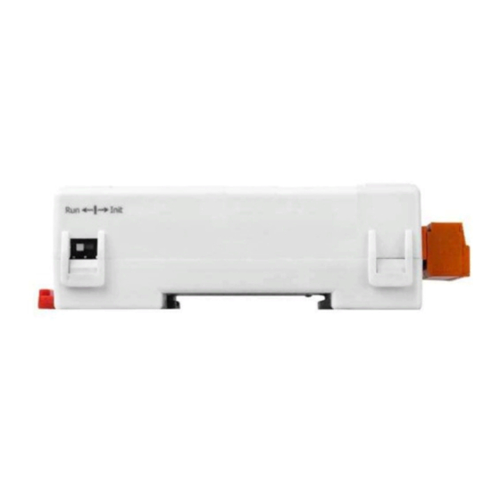
Page 133: Appendix
It is difficult to communicate with the module when the configuration of the module is unknown. To help avoid this problem, the tM series has a special mode called “INIT mode”. When the module is powered on in “INIT mode” the configuration of the module is reset as follows, allowing it to be operated as normal. - Page 134 The tM modules have the INIT switch located on the right side of the module to allow easier access to the INIT mode. For these modules, INIT mode is accessed by sliding the INIT switch to the Init position as shown below. tM Series DIO User Manual, Rev: A1.3 7PH-013-A13...
-
Page 135: Dual Watchdog Operation
The tM series modules include an internal Dual Watchdog, making the control system more reliable and stable. For more information regarding the Dual Watchdog, please refer to Chapter 5 of the “Getting Started For I-7000 Series... -
Page 136: Frame Ground
Connect the frame ground terminal to a wire/DIN rail and connect the wire/DIN rail to the earth ground will provide a better protection for the module. tM Series DIO User Manual, Rev: A1.3 7PH-013-A13... -
Page 137: Reset Status
$AA5 command is sent, it means the module has been reset and the digital output value had been changed to the power-on value. tM Series DIO User Manual, Rev: A1.3 7PH-013-A13... -
Page 138: Safe Value And Power-On Value Of Digital Output
Both the safe value and power-on value are set by the ~AA5V command. Refer to Section 2.30 for details. tM Series DIO User Manual, Rev: A1.3 7PH-013-A13... -
Page 139: Latched Digital Input
B period. For details of the read latched digital input command, please refer to Sections 2.17 and 3.1. tM Series DIO User Manual, Rev: A1.3 7PH-013-A13... -
Page 140: Dn Module
The DN modules are the I/O extension of the tM modules. They can drive more power and heavy load. User may use tM modules to control the DN modules to drive the loads. tM Series DIO User Manual, Rev: A1.3 7PH-013-A13... -
Page 141: Dn-Ssr4
Rated Load Current Surge Current 50 A Max. Off-State 5.0 mA Leakage Current Operate Time 1/2 cycle of voltage sine wave + Input Impedance 1.5K Ohms Power Input +24 VDC DIN-Rail Mounted tM Series DIO User Manual, Rev: A1.3 7PH-013-A13... -
Page 142: Dn-Pr4
Electric Life 100 x 10 operations min. Operate/Release Time Max. 10 ms / 5 ms Dielectric Strength 2000 VAC 1 minute Nominal Coil Power 360 mW Power Input +24 VDC DIN-Rail Mounted tM Series DIO User Manual, Rev: A1.3 7PH-013-A13... -
Page 143: Rm-104, Rm-108, And Rm-116
Contact Material AgCdO Min. Life 100,000 operations Dimensions RM-104 78 mm x 77 mm RM-108 135 mm x 77 mm RM-116 270 mm x 77 mm Power Input +24 VDC DIN-Rail Mounted tM Series DIO User Manual, Rev: A1.3 7PH-013-A13... -
Page 144: A.7.4 Rm-204, Rm-208, Rm-216
Contact Material AgNi Min. Life 100,000 operations Dimensions RM-204 78 mm x 77 mm RM-208 135 mm x 77 mm RM-216 270 mm x 77 mm Power Input +24 VDC DIN-Rail Mounted tM Series DIO User Manual, Rev: A1.3 7PH-013-A13...
Need help?
Do you have a question about the tM Series and is the answer not in the manual?
Questions and answers