Table of Contents
Advertisement
Quick Links
ND2000A - 02x - xx0
RADIOBEACON TRANSMITTER
Nautel Maine Inc.
201 Target Industrial Circle,
Bangor, Maine USA 04401
Phone: (207) 947-8200
Fax: (207) 947-3693
ISO 9002 REGISTERED
TECHNICAL INSTRUCTIONS
500 WATTS
(190 kHz to 535 kHz)
NAPE72 Keyer PWB
Original Issue ....................15 October 2004
Change 1...........................15 January 2005
e-mail: support@nautel.com
web: www.nautel.com
© Copyright 2005 NAUTEL. All rights reserved
Nautel Limited
10089 Peggy's Cove Road
Hackett's Cove, NS Canada B3Z 3J4
Phone: (902) 823-3900
Fax: (902) 823-3183
ISO 9001 REGISTERED
Advertisement
Table of Contents

Related Manuals for Nautel ND2000A-02x-xx0 Series


Summary of Contents for Nautel ND2000A-02x-xx0 Series
- Page 1 201 Target Industrial Circle, 10089 Peggy’s Cove Road Bangor, Maine USA 04401 Hackett’s Cove, NS Canada B3Z 3J4 Phone: (207) 947-8200 Phone: (902) 823-3900 Fax: (207) 947-3693 Fax: (902) 823-3183 ISO 9002 REGISTERED ISO 9001 REGISTERED © Copyright 2005 NAUTEL. All rights reserved...
- Page 2 500 WATT RADIOBEACON TRANSMITTER ND2000A-02x-xx0 LIST OF EFFECTIVE PAGES The list of effective pages lists the status of all pages in this manual. Pages of the original issue are identified by a zero in the Change No. column. Pages subsequently changed are identified by the date of the change number. On a changed page, the text affected by the latest change is indicated by a vertical bar in the margin opposite the changed material.
- Page 3 500 WATT RADIOBEACON TRANSMITTER ND2000A-02x-xx0 LIST OF EFFECTIVE PAGES (Continued) CHANGE CHANGE PAGE DATE PAGE DATE 15 October 2004 15 October 2004 15 October 2004 15 October 2004 15 October 2004 15 October 2004 15 October 2004 15 October 2004 15 October 2004 15 October 2004 4-10...
- Page 4 500 WATT RADIOBEACON TRANSMITTER ND2000A-02x-xx0 LIST OF EFFECTIVE PAGES (Continued) CHANGE CHANGE PAGE DATE PAGE DATE 7-37 15 October 2004 SD-13 15 October 2004 7-38 15 October 2004 SD-14 15 October 2004 7-39 15 October 2004 10-1 15 October 2004 7-40 15 October 2004 10-2...
- Page 5 500 WATT RADIOBEACON TRANSMITTER ND2000A-02x-xx0 ARTIFICIAL RESPIRATION (MOUTH-TO-MOUTH) START MOUTH-TO-MOUTH BREATHING IMMEDIATELY. SECONDS COUNT. Do not wait to loosen clothing, warm the casualty, or apply stimulants. ASSESS RESPONSIVENESS OF CASUALTY. Do not jar Figure 1) casualty or cause further physical injury ( IF POSSIBLE, SEND A BYSTANDER TO GET MEDICAL Figure 2) HELP.
- Page 6 500 WATT RADIOBEACON TRANSMITTER ND2000A-02x-xx0 GENERAL RULES FOR TREATMENT FOR BURNS, BLEEDING, AND SHOCK After casualty has revived, treat for injuries and shock. Reassure casualty. Try to make him comfortable. Keep him reasonably warm but do not apply heat. If thirsty, liquids may be given but no alcohol (no liquids should be given in cases of severe burns). Treat burns or wounds.
- Page 7 500 WATT RADIOBEACON TRANSMITTER ND2000A-02x-xx0 ELECTRIC SHOCK - RESCUE METHODS Electricity can damage the body in a number of ways. It may interfere with the proper functioning of the nervous system and the heart action, it can subject the body to extreme heat and can cause severe muscular contractions. The path that the current of electricity takes through the body is important.
- Page 8 500 WATT RADIOBEACON TRANSMITTER ND2000A-02x-xx0 TOXIC HAZARD WARNING There are devices used in this equipment containing BERYLLIUM OXIDE ceramic, which is non-hazardous during normal device operation and under normal device failure conditions. These devices are specifically identified in the equipment manual’s parts list(s). DO NOT cut, crush or grind devices because the resulting dust may be HAZARDOUS IF INHALED.
- Page 9 Nautel for repair. The repairs will be made without charge to the Customer. Where warranty replacements or repair are provided under items 2 or 3, Nautel will pay that part of the shipping costs incurred in returning the part/assembly to the Customer.
- Page 10 MODULE EXCHANGE SERVICE In order to provide Nautel customers with a fast and efficient service in the event of a problem, Nautel operates a factory rebuilt, module exchange service which takes full advantage of the high degree of module redundancy in Nautel equipment.
-
Page 11: Table Of Contents
500 WATT RADIOBEACON TRANSMITTER ND2000A-02x-xx0 TABLE OF CONTENTS Section Page GENERAL INFORMATION INTRODUCTION........................1-1 PURPOSE AND SCOPE OF MANUAL ................1-1 PURPOSE OF EQUIPMENT....................1-1 FACTORY REPAIR SERVICE..................... 1-1 MECHANICAL DESCRIPTION.................... 1-1 1.5.1 TRANSMITTER CHASSIS....................1-1 DUPLICATED MODULES/ASSEMBLIES ................1-2 TECHNICAL SUMMARY ..................... - Page 12 500 WATT RADIOBEACON TRANSMITTER ND2000A-02x-xx0 TABLE OF CONTENTS (Continued) Section Page THEORY OF OPERATION (Continued) 2.5.9.4 Line Volts Compensation/Power Trim Control .............. 2-7 2.5.9.5 PWM Square-Wave Generator ..................2-7 2.5.9.6 Ramp Integrator......................2-7 2.5.9.7 Linear Attenuator ......................2-8 2.5.9.8 Variable Pulse-Width Generator ..................2-8 2.5.9.10 Balanced Drive .......................
- Page 13 500 WATT RADIOBEACON TRANSMITTER ND2000A-02x-xx0 TABLE OF CONTENTS (Continued) Section Page INSTALLATION AND PREPARATION FOR USE GENERAL ..........................3-1 3.1.1 VISUAL INSPECTION ......................3-1 TEST EQUIPMENT....................... 3-1 SITE REQUIREMENTS ......................3-1 3.3.1 LIGHTNING/SAFETY GROUND ..................3-1 3.3.2 ANTENNA SYSTEM ......................3-1 3.3.3 ELECTRICAL POWER ......................
- Page 14 500 WATT RADIOBEACON TRANSMITTER ND2000A-02x-xx0 TABLE OF CONTENTS (Continued) Section Page INSTALLATION AND PREPARATION FOR USE (Continued) 3.7.5 MEAN LEVEL OF AC POWER SOURCE................3-5 PARTS REQUIRED BUT NOT SUPPLIED................. 3-6 3.8.1 OSCILLATOR CRYSTALS ....................3-6 PRE-INSTALLATION PROCEDURES................3-6 3.9.1 DISASSEMBLY REQUIRED ....................
- Page 15 500 WATT RADIOBEACON TRANSMITTER ND2000A-02x-xx0 TABLE OF CONTENTS (Continued) Section Page OPERATING INSTRUCTIONS (Continued) 4.7.2 SWR-ALARM INDICATION ....................4-3 4.7.3 REMEDIAL ACTION IN BEACON MODE................4-3 4.7.4 REMEDIAL ACTION IN VOICE AND BEACON MODE ............4-3 MODULATION PERCENTAGE INDICATION ..............4-4 TESTING AND ADJUSTMENT GENERAL ..........................
- Page 16 500 WATT RADIOBEACON TRANSMITTER ND2000A-02x-xx0 TABLE OF CONTENTS (Continued) Section Page TESTING AND ADJUSTMENT (Continued) 5.4.2.2 Reflected Power Reading .................... 5-21 5.4.3 LOW AC VOLTAGE THRESHOLD ADJUSTMENT............5-21 5.4.4 LOW BATTERY VOLTAGE THRESHOLD ADJUSTMENT (DC OPTION INSTALLED). 5-22 5.4.4.1 Low Battery Voltage Threshold Adjustment Pre-requisites......... 5-22 5.4.4.2 Determination of Low Voltage Battery Threshold............
- Page 17 FAMILY TREE ........................7-1 MANUFACTURER'S INDEX....................7-1 HOW TO LOCATE INFORMATION FOR A SPECIFIC PART ......... 7-1 7.4.1 WHEN NAUTEL CONFIGURATION CONTROL NUMBER IS KNOWN......7-1 7.4.2 WHEN REF DES IS KNOWN ....................7-1 REFERENCE DESIGNATION INDEXES ................7-1 COLUMN CONTENT EXPLANATION ................7-1 7.6.1...
- Page 18 LIST OF ILLUSTRATIONS Number Title Page ND2000A Radiobeacon Transmitter ......................1-3 Nautel's Identification ..........................1-6 Positioning of Selector Plates E1 and E2....................3-10 External Input/Output Interface......................... 3-16 Carrier Oscillator Frequency - CW ......................6-10 Balanced Drive Output - CW ........................6-10 Carrier Oscillator - CW ..........................
- Page 19 500 WATT RADIOBEACON TRANSMITTER ND2000A-02x-xx0 LIST OF ILLUSTRATIONS (Continued) Number Title Page MD-15 Assembly Detail - NAE45G Exciter Module (Right Side View).............MD-15 MD-16 Assembly Detail - NAE45G Exciter Module (Rear View)..............MD-16 MD-17 Assembly Detail - NAPE72 Keyer PWB....................MD-17 MD-18 Assembly Detail - NAPE29C/02 Modulator Driver PWB ..............MD-18 MD-19 Assembly Detail - NAPE64A RF Oscillator PWB (Optional DGPS Input)..........MD-19 MD-20...
- Page 20 500 WATT RADIOBEACON TRANSMITTER ND2000A-02x-xx0 LIST OF TABLES (Continued) Number Title Page Functional Test/Adjustment Check List ....................5-27 Morse Code Characters..........................5-31 Manufacturers' Code to Address Index ..................... 7-3 Ref Des Index - ND2000A-02x-xx0 (500 Watt) Radiobeacon Transmitter ..........7-7 Ref Des Index –...
-
Page 21: General Information
Nautel provides a factory module repair The control/monitor panel (A1) is mounted on a service for users of Nautel's transmitters. Users who hinged door at the top, front section of the transmitter. do not have repair facilities or who are not able to... -
Page 22: Glossary Of Terms
500 WATT RADIOBEACON TRANSMITTER ND2000A-02x-xx0 Table 1-1 Duplicated Modules/Assemblies NAUTEL REFERENCE NOMENCLATURE DESCRIPTION DESIGNATION NAP13B/02 Modulator/Power Amplifier A2 and A3 NAE45G/02 or 04 Exciter A4 and A5 NAS25B/03 or NAS25B/04 Power Supply A7 and A8 1.5.1.2 Modulator/power amplifier modules (A2/ TECHNICAL SUMMARY A3) are located below control monitor panel (A1). -
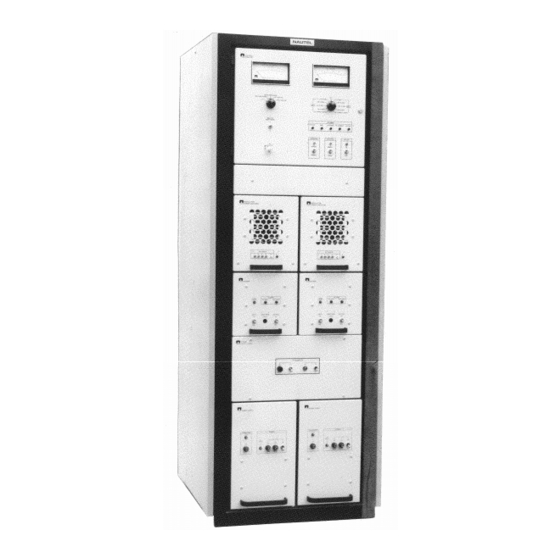
Page 23: Nd2000A Radiobeacon Transmitter
500 WATT RADIOBEACON TRANSMITTER ND2000A-02x-xx0 Figure 1-1 ND2000A Radiobeacon Transmitter Page 1-3 15 January 2005... -
Page 24: Technical Summary
500 WATT RADIOBEACON TRANSMITTER ND2000A-02x-xx0 Table 1-2 Technical Summary Equipment Name......................LF/MF Radiobeacon Transmitter Equipment Type Number .............................ND2000A Frequency Range............................190 to 535 kHz Frequency Control Standard............................RF Synthesizer Optional ........................Crystal Controlled Oscillator Frequency Tolerance ............± 0.0003% (RF synthesizer) Over Full Environmental Range ±... - Page 25 500 WATT RADIOBEACON TRANSMITTER ND2000A-02x-xx0 Table 1-2 Technical Summary (Continued) Weight (unpacked) ..................Approximately 257 kilograms (565 pounds) Dimensions Height........................165 centimetres (65 inches) Width ........................... 61 centimetres (24 inches) Depth........................... 61 centimetres (24 inches) Airflow ........................Approximately 90 cubic feet/minute Heat Flushing (Maximum).........................1000 BTUs/hour REMOTE MAINTENANCE MONITORING INPUTS/OUTPUTS (1) ..............................Forward Power...
-
Page 26: Nautel's Identification
500 WATT RADIOBEACON TRANSMITTER ND2000A-02x-xx0 Nautel's ND family of radiobeacon transmitters are identified by a multi-part identifier. This identifier is stamped on the transmitter's nameplate and identifies a specific configuration of radiobeacon in accordance with the following: Figure 1-2 Nautel's Identification... - Page 27 500 WATT RADIOBEACON TRANSMITTER ND2000A-02x-xx0 Table 1-3 Test Equipment and Special Tools NOMENCLATURE PART, MODEL, OR TYPE NUMBER APPLICATION (EQUIVALENTS MAY BE USED) Dummy Load Resistive 50-ohm dummy load rated at Provides precise 50-ohm load 1000 watts (twice the power rating of the during calibration and trouble transmitter) shooting.
-
Page 28: Glossary Of Terms
500 WATT RADIOBEACON TRANSMITTER ND2000A-02x-xx0 Table 1-4 Glossary of Terms TERM DESCRIPTION Basic timing increment derived from master clock in keying unit. Nominally 125 milliseconds long Character Letter or number in the beacon identification signal Element Smallest divisible part of a character. May be either a dot or a dash Frame Selected, fixed interval of time which is sufficiently long to... -
Page 29: Theory Of Operation
500 WATT RADIOBEACON TRANSMITTER ND2000A-02x-xx0 SECTION 2 THEORY OF OPERATION GENERAL indicates the transmitter's B- operating voltage is The theory of operation for the subject being produced by an external dc power source transmitter is presented in this section. (battery etc). information is presented in detail using the electrical schematics as a reference. -
Page 30: Alarm Lamps
500 WATT RADIOBEACON TRANSMITTER ND2000A-02x-xx0 2.3.4 ALARM LAMPS: following 2.3.5 SELECT MAIN TX SWITCHING: The paragraphs explain each alarm lamp function: switch selects which side of the SELECT MAIN TX subject transmitter will be the main operating side 2.3.4.1 Battery-Alarm Lamp: The . -
Page 31: Modulator (A2A1)
500 WATT RADIOBEACON TRANSMITTER ND2000A-02x-xx0 A modulator/power amplifier can provide up to 2000 MOSFET A1Q1 does not exceed 13.0 V. Transistors watts of peak envelope power or 500 watts of A1A1Q2/Q3 act as switches between a logic 1 and a continuous carrier power, over a frequency range of logic 0 to charge and discharge the capacitive load 190 kHz to 535 kHz. -
Page 32: Exciter Module
500 WATT RADIOBEACON TRANSMITTER ND2000A-02x-xx0 positive, the gate of MOSFET A2Q4 will be positive, amplifier (A4) which increases the RF drive to the the gates of MOSFETS A2Q2/Q3 will be negative. power level required by the modulator/power MOSFETS A2Q1/Q4 will be turned on, MOSFETS amplifier stage and regulated +15 V and -15 V power A2Q2/Q3 will be turned off. -
Page 33: Keyer Pwb (A4A1)
500 WATT RADIOBEACON TRANSMITTER ND2000A-02x-xx0 2.5.5 KEYER PWB (A4A1): (See figure SD-6) 2.2.3.2 Each EEPROM (U9 and U10) has three The keyer is a self-contained logic block that inputs ( ) and an output ( ). The three automatically generates keyed audio tone signals inputs are tied to the corresponding pin on the that are used to modulate the transmitter. -
Page 34: Rf Oscillator Pwb (A4A3)
500 WATT RADIOBEACON TRANSMITTER ND2000A-02x-xx0 2.5.6 RF OSCILLATOR PWB (A4A3) (see 12-bit digital to analog converter is low-pass filtered figure SD-9): The RF oscillator PWB is a dual to provide a sinusoidal continuous output. The sine purpose low level RF drive source for the exciter. It wave is digitized and divided by a factor of four to contains a crystal controlled oscillator circuit that can obtain the carrier frequency. -
Page 35: Line Volts Compensation/Power Trim Control
500 WATT RADIOBEACON TRANSMITTER ND2000A-02x-xx0 level and audio information. Logic circuits monitor when keyed tone and voice are selected. VOICE MOD RF drive level and modulation pulse width output. potentiometer R21 is adjusted for the voice They turn on the appropriate and/or modulation level. -
Page 36: Linear Attenuator
500 WATT RADIOBEACON TRANSMITTER ND2000A-02x-xx0 Figure 2-1 Simplified Schematic of Pulse-Width Differential Amplifier 2.5.9.7 Linear Attenuator: The linear attenuator 2.5.9.9 For explanation purposes, assume the circuit contains operational amplifier U7A, unity gain audio signal is a DC reference voltage that does not amplifier U7B, transistors Q2/Q4 and their associated contain an audio component. -
Page 37: Pulse-Width Fault Detector
500 WATT RADIOBEACON TRANSMITTER ND2000A-02x-xx0 ensures the leading and trailing edges of the RF drive alarm lamp will turn on. After rectangular waveform are sharp. The mod drive approximately five seconds the voltage being applied output at J2-6 is a low impedance pulse-width to the base of transistor Q3 will decay through modulated signal switching between +15 volts dc and resistors R60/R61, transistor Q3 will be reversed... - Page 38 500 WATT RADIOBEACON TRANSMITTER ND2000A-02x-xx0 gate voltage and therefore their on time for each half is adjusted for a DC voltage that will maintain cycle of the ac voltage source. A1U2C's output (DC reference voltage) at a level that will result in a B- VDC output of 50.0 V dc by 2.7.1.1 Diodes A1CR1/CR2 full-wave rectify the controlling the on-time of thyristors Q1/Q2.
-
Page 39: B- Vdc To +24 Volt Dc Converter Pwb (A7A2)
500 WATT RADIOBEACON TRANSMITTER ND2000A-02x-xx0 2.7.2 VOLT biased (turned on). Transistor A3Q2 will be reverse CONVERTER PWB (A7A2): The B- voltage is biased (turned off). +15 V dc will be passed to ac applied through fuse A7F1 and inductor A2L1 to the sense connectors J1-8 and J1-12. -
Page 40: Fwd/Refl Power Probe (A9A2)
500 WATT RADIOBEACON TRANSMITTER ND2000A-02x-xx0 2.8.2 FWD/REFL POWER PROBE (A9A2): 2.8.2.5 Under circumstances should Voltage transformer A2T1, current transformer A2T2 modulation level, as measured by the current or and their associated components provide voltage and voltage probe, be adjusted beyond 95 % in an effort to current arms of a forward/reflected power bridge, offset the sideband attenuation which occurs in the which samples the RF output signal. -
Page 41: A/B Main Select
500 WATT RADIOBEACON TRANSMITTER ND2000A-02x-xx0 control signal is applied to 'remote off' input J4-1, 2.9.4 MONITOR -15 VOLTS DC CIRCUIT: relay K1 will energize, the B- operating voltage will The B- voltage is applied across resistor R74 and be inhibited. A 'reset enable' (ground) control signal zener diode CR16. -
Page 42: Carrier Threshold Circuit
500 WATT RADIOBEACON TRANSMITTER ND2000A-02x-xx0 2.9.5.2 The output from operational amplifier U4A 2.9.7 CHANGEOVER DELAY CIRCUIT: is applied across a differentiating circuit consisting of The changeover delay circuit can be adjusted for a resistor R38 and capacitor C12. The differentiating changeover time delay of between 20 and 80 seconds. -
Page 43: Forward Power Cal
500 WATT RADIOBEACON TRANSMITTER ND2000A-02x-xx0 base of transistor Q12. Transistor Q12 will be reverse turn protects the transmitter from excessive peak biased and turn off. A shutdown control signal will current which would occur on the peaks of the be applied to relay K2 and to a shutdown-alarm lamp modulation envelope. -
Page 44: Power Trim Interface Control Circuit
500 WATT RADIOBEACON TRANSMITTER ND2000A-02x-xx0 go high. This output will be passed to four separate applied through buffer U1D and passed to refl pwr circuits. (remote) connector J8-1 for external use. One portion of U10B's output will be applied to the 2.9.16 MOD% CONTROL... -
Page 45: Monitor Bypass Circuit
500 WATT RADIOBEACON TRANSMITTER ND2000A-02x-xx0 2.9.18 AC POWER MONITOR CIRCUIT (Dc BATTERY CONTROL PANEL (A11) Option Not Installed): When the dc power source ASSEMBLY (see figure SD-14) option is not installed, the output of the ac power 2.10 Battery control panel assembly contains monitor circuit is paralleled with the output of the sensing circuits which automatically switch the SWR cutback circuit. -
Page 46: Low Battery Voltage Monitor
500 WATT RADIOBEACON TRANSMITTER ND2000A-02x-xx0 2.10.1.1 Low Battery Voltage Monitor: When 2.10.1.1.2 switch S1 must be BATTERY RESET operating from an external dc power source (battery), momentarily closed (ground) for a nominal three to the AC sense inputs on P1-7 and P1-5 are removed. five seconds. - Page 47 500 WATT RADIOBEACON TRANSMITTER ND2000A-02X-xx0 SECTION 3 INSTALLATION AND PREPARATION FOR USE GENERAL 3.3.1 LIGHTNING/SAFETY GROUND: The This section contains the information transmitter site must contain a lightning/safety ground required to prepare the equipment site to receive the system to protect the transmitter from lightning subject transmitter and the information required to induced voltage...
- Page 48 500 WATT RADIOBEACON TRANSMITTER ND2000A-02X-xx0 3.3.4 ELECTRICAL POWER CABLING: 3.4.1 EXTERNAL AUDIO SOURCE: The ac power cable must be provided by the user. A external audio source must be provided. dc power cable, (if applicable) must also be provided impedance of the audio source must be a balanced for the user.
- Page 49 500 WATT RADIOBEACON TRANSMITTER ND2000A-02X-xx0 3.4.2.6 Press-To-Talk Control: The press-to-talk 3.4.3.4 Audio Monitor: A transformer coupled switching circuit should be the equivalent of a 600 ohm audio output is provided between TB3-22 normally open, single pole, single throw switch. and TB3-23 for external monitoring. When set to its closed position (press-to-talk), it shall apply a ground to TB4-19.
- Page 50 500 WATT RADIOBEACON TRANSMITTER ND2000A-02X-xx0 13 as the SWR alarm output. When the reflected 3.5.1 TRANSMITTER CABINET CRATE: power is excessive and causing the carrier level to be The transmitter is packed partially disassembled in a cutback (reduced), the transistor will be forward wooden crate that is approximately 178 cm (70 biased and a current sink-to-ground will be applied to inches) x 74 cm (29 inches) x 76 cm (30 inches).
-
Page 51: Mean Level Of Ac Power Source
500 WATT RADIOBEACON TRANSMITTER ND2000A-02X-xx0 3.5.3 EXCITER MODULATOR/ 3.7.1 CARRIER FREQUENCY: Determine POWER AMPLIFIER MODULE CRATE: The the transmitter's assigned carrier frequency and record exciter and modulator/power amplifier modules are frequency in the Established Reference section of packed fully assembled in a wooden crate that is table 5-2. -
Page 52: Parts Required But Not Supplied
500 WATT RADIOBEACON TRANSMITTER ND2000A-02X-xx0 Table 3-1 Crystal Operating Frequencies FREQUENCY (kHz) MULTIPLY BY CRYSTAL FREQUENCY (kHz) 190 - 250 3040 to 4000 251 - 500 2000 to 4000 501 - 535 2000 to 2140 PARTS REQUIRED BUT NOT SUPPLIED PRE-INSTALLATION PROCEDURES Some parts required to complete the Assembly of the transmitter must be... -
Page 53: Keyer Pwb Pre-Installation
500 WATT RADIOBEACON TRANSMITTER ND2000A-02X-xx0 A link must be connected between printed Select the keyer type, as indicated by the wiring pad and pad (enables crystal alphanumeric displays, noting the options are controlled oscillator). . If is selected, proceed to ICAO TRAN TRAN... -
Page 54: Keyed Tone Frequency
500 WATT RADIOBEACON TRANSMITTER ND2000A-02X-xx0 Table 3-2 Selecting Primary Winding Taps for Power Transformers A7T1/A8T1 AC SUPPLY TRANSFORMER TAPS VOLTAGE (RMS) (WIRE #5) (WIRE #6) Set up the specific characters to be keyed 3.9.4 POWER TRANSFORMERS A7T1 and (between 1 and 4 for ;... - Page 55 500 WATT RADIOBEACON TRANSMITTER ND2000A-02X-xx0 Table 3-3 Selecting Frequency Band Links on Harmonic Filter A12 FREQUENCY PARALLEL SERIES PARALLEL BAND (kHz) SERIES INDUCTORS CAPACITORS CAPACITORS INDUCTORS (C1/C2/C3/C4) (C5/C6/C7/C8) FROM L3-1 L4-1 (QUANTITY) (QUANTITY) 190.0 198.4 L1-6 to L2-6 L4-6 L3-6 198.4 216.2 L1-5...
-
Page 56: Positioning Of Selector Plates E1 And E2
500 WATT RADIOBEACON TRANSMITTER ND2000A-02X-xx0 From the Series Inductor column of table 3-3, Position series capacitor selector plate E1 over determine the taps of inductors A9L1 and A9L2 capacitors C1, C2, C3 and C4 so it places, in- that are to be interconnected. circuit, the number of capacitors identified in step (c). -
Page 57: Installation Procedures
500 WATT RADIOBEACON TRANSMITTER ND2000A-02X-xx0 INSTALLATION PROCEDURES Locate modulator/power amplifier module tray 3.10 following procedures must openings on the front of the transmitter cabinet. performed while installing the transmitter: Install the two modulator/power amplifier 3.10.1 TRANSMITTER MODULE modules into their respective trays. INSTALLATION: Install the modulator/power Firmly secure attaching hardware to retaining... -
Page 58: External Input/Output Interface Connections
500 WATT RADIOBEACON TRANSMITTER ND2000A-02X-xx0 Mate connector P7, which terminates a Connect the input/output conductors to the cableform flying lead, with connector J2 of appropriate terminals of barrier strips TB3 and exciter module A5. TB4 using figure 3-2 as a guide. Mate connector P8, which terminates a 3.10.3 RF OUTPUT CABLE CONNECTION:... -
Page 59: First Stage (Initial Start-Up)
500 WATT RADIOBEACON TRANSMITTER ND2000A-02X-xx0 North American Type Supply SECOND STAGE (INITIAL START-UP) 230 VAC (line-to-line) 3.12 The second stage of initial start-up is to connect the transmitter's output to its antenna system, TB1-1 Line A (115 V ac) interfaced by a suitable antenna tuning arrangement TB1-2 Line B (115 V ac) and to adjust the antenna tuning unit in accordance... -
Page 60: Third Stage (Initial Start-Up)
500 WATT RADIOBEACON TRANSMITTER ND2000A-02X-xx0 Adjust or verify antenna tuning unit is adjusted If the intended carrier level is less than 500 watts, it (by personnel at antenna tuning unit site) in will be necessary to adjust the carrier level fault accordance with instructions in the ATU threshold level, while operating into the antenna instruction manual. - Page 61 500 WATT RADIOBEACON TRANSMITTER ND2000A-02X-xx0 NOTE switch to TEST-Power/Mod MOD-SET If the intended modulation depth is less than 95%, it will be necessary to adjust the modulation depth fault Adjust the potentiometer for SET 100 % MOD threshold level, while operating into the antenna 100% indication on the lower scale of the TEST- system, as detailed in paragraph 5.3.15.3 and the...
-
Page 62: External Input/Output Interface
500 WATT RADIOBEACON TRANSMITTER ND2000A-02X-xx0 Figure 3-2 External Input/Output Interface Page 3-16 15 January 2005... -
Page 63: Operating Instructions
500 WATT RADIOBEACON TRANSMITTER ND2000A-02x-xx0 SECTION 4 OPERATING INSTRUCTIONS GENERAL 4.3.3 EXCITER MODULE CONTROLS This section provides the information AND INDICATORS: Figures MD-13 to MD-21 required to place the subject transmitter in operation. depict the controls and indicators on exciter modules Normally, the transmitter will not be attended during A4/A5 and their associated printed wiring boards/ use. -
Page 64: Miscellaneous (Cabinet/Interface Panel) Controls And Indicators
500 WATT RADIOBEACON TRANSMITTER ND2000A-02x-xx0 4.3.9 MISCELLANEOUS (CABINET/ TURNING ON TRANSMITTER INTERFACE PANEL) CONTROLS Turn on transmitter as described in INDICATORS: Figure MD-1 depicts the controls on paragraph 5.3.2 for initial startup and after repairs that the transmitter cabinet and figure MD-29 depicts the may have affected the adjustment accuracy, at other controls on the interface panel assembly. -
Page 65: Swr-Alarm Indication
500 WATT RADIOBEACON TRANSMITTER ND2000A-02x-xx0 4.7.1 CURRENT ALARM 4.7.3 REMEDIAL ACTION IN BEACON INDICATION: A current probe in the input to MODE: When operating in beacon (no voice) mode, harmonic filter A9 provides an RF current sample the modulation depth should be reduced by adjusting that is representative of the RF current in the active potentiometer (R19) counter clockwise TONE LEVEL... -
Page 66: Modulation Percentage Indication
500 WATT RADIOBEACON TRANSMITTER ND2000A-02x-xx0 Table 4-1 Preliminary Switch Settings NOMENCLATURE INITIAL TEST OPERATING USED IN TEXT SETTING SETTING SETTING SPEAKER A10S3 MONITOR A1S4 BYPASS BYPASS NORMAL TEST-Volts/Current A1S5 SELECT MAIN TX A1S3 A or B A1S1 TEST-Power/Mod A1S6 CONTROL A1S2 LOCAL LOCAL... -
Page 67: Control/Monitor Panel Controls And Indicators
500 WATT RADIOBEACON TRANSMITTER ND2000A-02x-xx0 Table 4-2 Control/Monitor Panel Controls and Indicators PANEL MARKING/ NOMENCLATURE FUNCTION USED IN TEXT A1A1DS1 MD-2 STANDBY-ALARM When turned on, indicates the transmitter has switched from the selected main-side to standby-side. A1A1DS2 MD-2 SWR-ALARM When turned on, indicates a reflected power in excess of 60 watts has been sensed at the output of the harmonic filter. - Page 68 500 WATT RADIOBEACON TRANSMITTER ND2000A-02x-xx0 Table 4-2 Control/Monitor Panel Controls and Indicators (Continued) PANEL MARKING/ NOMENCLATURE FUNCTION USED IN TEXT A1S1 MD-2 Turns the transmitter Resets the transmitter to its original state when set to then returned to . (If operating in the standby mode, transmitter will reset to main).
-
Page 69: Modulator/Power Amplifier Module Controls And Indicators
500 WATT RADIOBEACON TRANSMITTER ND2000A-02x-xx0 Table 4-3 Modulator/Power Amplifier Module Controls and Indicators PANEL MARKING/ NOMENCLATURE FUNCTION USED IN TEXT *A9DS1 MD-4 Indicates the B- voltage is being applied when on. *A9DS2 MD-4 PA VOLTS - 4 Indicates modulator *A7 is functioning and is applying a modulated B- voltage to power amplifier *A8 when *A9DS3 MD-4... -
Page 70: Exciter Module Controls And Indicators
500 WATT RADIOBEACON TRANSMITTER ND2000A-02x-xx0 Table 4-4 Exciter Module Controls and Indicators PANEL MARKING/ NOMENCLATURE FUNCTION USED IN TEXT A1DS1 MD-17 KEYER FAULT Indicates a problem has occurred with one or both EEPROMs on the keyer PWB. Action taken on the transmitter is dependent on the setting of the jumper (E4). - Page 71 500 WATT RADIOBEACON TRANSMITTER ND2000A-02x-xx0 Table 4-4 Exciter Module Controls and Indicators (Continued) PANEL MARKING/ NOMENCLATURE FUNCTION USED IN TEXT A2C22 MD-18 PWM Freq Adjusted to set the frequency of the PWM squarewave (ramp) generator to the optimum frequency (nominally 70kHz) for the assigned carrier frequency.
- Page 72 500 WATT RADIOBEACON TRANSMITTER ND2000A-02x-xx0 Table 4-4 Exciter Module Controls and Indicators (Continued) PANEL MARKING/ NOMENCLATURE FUNCTION USED IN TEXT #A3R41 MD-♦ IPM BAL Not used in NDB transmitters #A3S1 MD-♦ X 1000 Rotary 10-position BCD switch that selects the carrier frequency’s thousands digit (either ‘0’...
- Page 73 500 WATT RADIOBEACON TRANSMITTER ND2000A-02x-xx0 Table 4-4 Exciter Module Controls and Indicators (Continued) PANEL MARKING/ NOMENCLATURE FUNCTION USED IN TEXT MD-13 RF DRIVE ALARM Indicates the RF drive level has fallen below the minimum RF drive threshold when on. MD-13 MOD DRIVE ALARM Indicates the on/off radio of the mod drive signal's variable pulse width is incorrect and the mod drive...
-
Page 74: Power On/Off Panel Controls And Indicators
500 WATT RADIOBEACON TRANSMITTER ND2000A-02x-xx0 Table 4-5 Power On/Off Panel Controls and Indicators PANEL MARKING/ NOMENCLATURE FUNCTION USED IN TEXT A6DS1 MD-22 Power - Ac Line Indicates ac voltage present at power supply modules A7 and A8. A6F1 MD-22 BATTERY Fuses the transmitter's external dc power source (battery) at 30 amperes. -
Page 75: Power Supply Module Controls And Indicators
500 WATT RADIOBEACON TRANSMITTER ND2000A-02x-xx0 Table 4-6 Power Supply Module Controls and Indicators PANEL MARKING/ NOMENCLATURE FUNCTION USED IN TEXT *DS1 MD-23 CONVERTER-+24V Indicates B- V dc to +24 V dc converter is providing 24 V dc when on. *DS2 MD-23 POWER-DC SUPPLY Indicates the B- voltage is present when on. -
Page 76: Harmonic Filter Assembly Controls And Indicators
500 WATT RADIOBEACON TRANSMITTER ND2000A-02x-xx0 Table 4-7 Harmonic Filter Assembly Controls and Indicators PANEL MARKING/ NOMENCLATURE FUNCTION USED IN TEXT A9A2S1 MD-29 RF MON Determines the source of the RF output waveform for meter M1's modulation readings and for the TEST monitoring sample provided at the output... - Page 77 500 WATT RADIOBEACON TRANSMITTER ND2000A-02x-xx0 Table 4-8 Monitor PWB Controls and Indicators PANEL MARKING/ NOMENCLATURE FUNCTION USED IN TEXT A10DS1 MD-34 SET THRSH Flashes between tone periods during keyed MCW operation. Continuously on when RF carrier level falls below preset carrier fault threshold (normally -3.0 dB) or when modulation level falls below preset modulation fault threshold (normally -4.0 dB) or keying fails.
- Page 78 500 WATT RADIOBEACON TRANSMITTER ND2000A-02x-xx0 Table 4-8 Monitor PWB Controls and Indicators (Continued) PANEL MARKING/ NOMENCLATURE FUNCTION USED IN TEXT A10R107 MD-34 REFL PWR CAL Adjusted to precisely set the reflected power indication on the meter, when the switch is set to TEST TEST , during test/adjustment.
-
Page 79: Battery Panel Controls And Indicators
500 WATT RADIOBEACON TRANSMITTER ND2000A-02x-xx0 Table 4-9 Battery Panel Controls and Indicators PANEL MARKING/ NOMENCLATURE FUNCTION USED IN TEXT A11S1 MD-36 BATTERY RESET Resets transmitter's low battery voltage shutdown circuit, utilizing a slow charge circuit, when discharged batteries are replaced by charged batteries. Used only when ac power is not being applied. -
Page 80: Miscellaneous (Cabinet/Interface Panel) Controls And Indicators
500 WATT RADIOBEACON TRANSMITTER ND2000A-02x-xx0 Table 4-10 Miscellaneous (Cabinet/Interface Panel) Controls and Indicators PANEL MARKING/ NOMENCLATURE FUNCTION USED IN TEXT MD-29 0.25A Fuses B- V dc (A) applied to TB4-8, for external monitoring, at 0.25 amperes. MD-29 0.25A Fuses B- V dc (B) applied to TB4-9, for external monitoring, at 0.25 amperes. -
Page 81: Testing And Adjustment
500 WATT RADIOBEACON TRANSMITTER ND2000A-02x-xx0 SECTION 5 TESTING AND ADJUSTMENTS GENERAL The depth of the modulation envelope is referred to as This section contains adjustment the intended modulation depth in the following. The procedures that are performed in conjunction with modulation depth is normally dictated by the 'Q' of the functional tests. -
Page 82: Test/Adjustment Prerequisites
500 WATT RADIOBEACON TRANSMITTER ND2000A-02x-xx0 5.3.1 TEST/ADJUSTMENT TEST Verify harmonic filter A9's inductor taps and in- EQUIPMENT: The following test equipment is circuit capacitors have been selected and required to perform the functional test/adjustment connected, for the assigned carrier frequency, as procedures. -
Page 83: Dc Voltage Checks
500 WATT RADIOBEACON TRANSMITTER ND2000A-02x-xx0 Verify the requirements of paragraph 5.3.2 have switch to TEST-Volts/Current B-V - SIDE A been completed and are being met. meter indication shall be TEST-Volts/Current Verify AC power source voltage is within five between -50.0 and -52.0 V dc. percent of voltage used to select the primary NOTE winding taps of power transformers A7T1 and... -
Page 84: Carrier Frequency Check
500 WATT RADIOBEACON TRANSMITTER ND2000A-02x-xx0 switch to 5.3.5 CARRIER FREQUENCY CHECK: TEST-Volts/Current +15V - SIDE A Check the carrier (RF drive) frequency as follows: (m) Verify multimeter is connected between meter 5.3.5.1 RF Synthesizer Check: If the RF drive is M2 (+) and ground. -
Page 85: Rf Drive Output Level Check
500 WATT RADIOBEACON TRANSMITTER ND2000A-02x-xx0 Verify the appropriate link is installed on RF Connect a multimeter between connector oscillator A4A3 (A5A3) (PWB pad 'E' A4A4J3 (A5A4J3) and ground. connected to PWB pad ÷4, 8 or 16; PWB pad 'A' connected to PWB pad 'B') for the assigned Multimeter indication shall be between 12.0 and carrier frequency. -
Page 86: Rf Carrier Check
500 WATT RADIOBEACON TRANSMITTER ND2000A-02x-xx0 Oscilloscope waveform indication shall be necessary, adjust similar to the waveform depicted in figure 6-9, potentiometer A10R79 until TEST-Power/Mod with the negative going peaks at or slightly meter's forward power indication is precisely below the zero volt reference line. 500 watts. -
Page 87: B- Voltage (Mcw) Check
500 WATT RADIOBEACON TRANSMITTER ND2000A-02x-xx0 NOTE 5.3.10 B- VOLTAGE (MCW) CHECK: Check When reading modulation percentage on the B- voltage with the transmitter's RF output set to TEST- meter, always set switch the intended carrier level and the intended modulation Power/Mod TEST-Power/Mod and adjust... -
Page 88: Modulation Depth (A3E Mode) Check
500 WATT RADIOBEACON TRANSMITTER ND2000A-02x-xx0 Connect a shorting jumper between TB4-19 5.3.12 MODULATION DEPTH (A3E MODE) (press-to-talk) and ground. CHECK: Check the modulation depth when voice and tone (A3E mode) are simultaneously transmitted Connect an audio signal generator between as follows: TB4-22 and TB4-23 with shield if applicable to NOTE TB4-24 (see figure 3-3). -
Page 89: Identification Code Check
500 WATT RADIOBEACON TRANSMITTER ND2000A-02x-xx0 Oscilloscope waveform's modulation envelope Adjust potentiometer for a SPEAKER VOLUME (external voice audio) shall be 60% of intended clear audible keyed beacon identification tone. modulation depth. deciphered coded portion (m) If necessary, adjust potentiometer VOICE MOD % identification message shall be the station A4A2R21 (A5A2R21) -
Page 90: Fault Thresholds/Changeover Check
500 WATT RADIOBEACON TRANSMITTER ND2000A-02x-xx0 Standby 2 code variation, which is a 0.125 Oscilloscope waveform's modulation envelope second blip that occurs 0.875 seconds before the shall be the intended modulation depth. first ident character, shall be detected in the ident code. If necessary, adjust potentiometer TONE LEVEL... -
Page 91: Modulation Depth Fault Threshold Check
500 WATT RADIOBEACON TRANSMITTER ND2000A-02x-xx0 meter's forward power Determine the minimum modulation depth TEST-Power/Mod indication should be -3.0 dB from the intended (normally -4.0 dB when the carrier level fault carrier level. threshold is -3.0 dB) that is acceptable before transmitter changeover occurs. -
Page 92: Changeover/Shutdown Check
500 WATT RADIOBEACON TRANSMITTER ND2000A-02x-xx0 If requirement of step (m) is met, go to step (v); NOTE if not, complete steps (o) through (u). The changeover delay period, once set, is applicable to both sides of the transmitter. If either side 'A' or 'B' Adjust potentiometer A4A2R19 of the transmitter shuts down, the pre-selected delay... -
Page 93: Db To Power/Voltage Conversion
500 WATT RADIOBEACON TRANSMITTER ND2000A-02x-xx0 Table 5-1 dB to Power/Voltage Conversion VOLTAGE POWER VOLTAGE POWER VOLTAGE POWER 1.0000 1.0000 0.6310 0.3981 0.3981 0.1585 0.9886 0.9772 0.6237 0.3890 0.3936 0.1549 0.9772 0.9550 0.6166 0.3802 0.3890 0.1514 0.9661 0.9333 0.6095 0.3715 0.3846 0.1479 0.9550 0.9120... - Page 94 500 WATT RADIOBEACON TRANSMITTER ND2000A-02x-xx0 If the changeover delay time in step (k) is After the delay determined in step (c), the satisfactory, go to step (p); if not, complete steps selected side (main) transmitter will turn off and (m) through (o). lamp shall turn on [(see note STANDBY-ALARM after step (k)].
- Page 95 500 WATT RADIOBEACON TRANSMITTER ND2000A-02x-xx0 (al) lamp A1A1DS8 shall turn MONITOR-BYPASS off and selected side A or B shall remain on. Discontinue adjusting potentiometer O/P POWER (am) After the delay determined in step (c), the A4A2R48 (A5A2R48) when dummy load's forward selected side (main) transmitter will turn off and power indication exceeds 60 watts.
-
Page 96: Alarm Systems Check
500 WATT RADIOBEACON TRANSMITTER ND2000A-02x-xx0 Simultaneously monitor Adjust potentiometer A4A2R48 TEST-Power/Mod O/P POWER meter's reflected power indication and continue (A5A2R48) for precisely 500 watts, as indicated to adjust potentiometer A4A2R48 by dummy load's forward power indication. O/P POWER (A5A2R48) clockwise. switch to TEST-Power/Mod MOD-SET... -
Page 97: Rf Current-Alarm Check
500 WATT RADIOBEACON TRANSMITTER ND2000A-02x-xx0 5.3.18.1 Current-Alarm Check: lamp shall turn MONITOR-BYPASS lamp was checked in paragraph lamp and CURRENT-ALARM STANDBY-ALARM SHUTDOWN-ALARM 5.3.17. lamp shall turn off. 5.3.18.2 SWR-Alarm Check: lamp The selected side (main transmitter) shall turn SWR-ALARM was checked in paragraph 5.3.16. on and resume normal operation. -
Page 98: Rf Drive-Alarm Check
500 WATT RADIOBEACON TRANSMITTER ND2000A-02x-xx0 Measure and record oscilloscope mod drive Disconnect dc power supply from A4P4 waveform's on/off duty cycle, noting off period (A5P4). is zero volts and on period is ±15 volts. Install A4P4 (A5P4) on A4A4J3 (A5A4J3). The on time recorded in step (i) shall be between 59 and 65%. -
Page 99: Test/Adjustment Of Side B
500 WATT RADIOBEACON TRANSMITTER ND2000A-02x-xx0 Verify transmitter is operating at the intended NOTE carrier level (500 watts maximum) and the switch must be set to when SELECT MAIN TX intended modulation depth. instructed to set switches as tabulated for Test Settings in table 4-1. - Page 100 500 WATT RADIOBEACON TRANSMITTER ND2000A-02x-xx0 switch A6S1 to Adjust potentiometer A4A2R19 POWER-AC LINE TONE LEVEL (A5A2R19) for the intended modulation depth Verify lamp A7DS2 (A8DS2) and as indicated on meter. DC SUPPLY TEST-Power/Mod B- lamp A2A9DS1 (A3A9DS1) are on. Record meter's current TEST-Volts/Current...
-
Page 101: Reflected Power Reading
500 WATT RADIOBEACON TRANSMITTER ND2000A-02x-xx0 switch to Remove shorting clip from resistor A4A2R44 TEST-Power/Mod FWD PWR (A5A2R44). meter's forward power TEST-Power/Mod Install connector P13 on A9A2J1. indication shall be the intended carrier level. 5.4.3 LOW AC VOLTAGE THRESHOLD ADJUSTMENT: Adjust the low ac voltage threshold necessary, adjust circuit as follows:... - Page 102 500 WATT RADIOBEACON TRANSMITTER ND2000A-02x-xx0 switch A4S2 (A5S2) to 5.4.4 BATTERY VOLTAGE THRESHOLD ADJUSTMENT (DC OPTION switch to INSTALLED): Verify the low battery voltage Test-Power/Mod MOD-SET threshold is set to the level that will initiate a (m) Adjust potentiometer for a transmitter shutdown when the battery bank has SET 100 % MOD 100% modulation depth indication on...
-
Page 103: Determination Of Low Voltage Battery Threshold
500 WATT RADIOBEACON TRANSMITTER ND2000A-02x-xx0 5.4.4.2 Determination of Low Voltage Battery Calculate the current drain from the battery Threshold: If the low battery voltage threshold is not bank (I ), when its output voltage is at the known, calculate its level as follows: battery cut-off voltage level (V ), by dividing battery power consumption recorded as P... -
Page 104: Operational Adjustment Procedures
500 WATT RADIOBEACON TRANSMITTER ND2000A-02x-xx0 NOTE Repeat steps (g) through (k) until the If the low battery voltage threshold level has not been requirement of step (j) is met without further calculated, refer to paragraph 5.4.4.2 for the adjustment Battery Threshold procedure to perform this calculation. -
Page 105: Operational Adjustment Pre-Requisites
500 WATT RADIOBEACON TRANSMITTER ND2000A-02x-xx0 An audio signal generator, with appropriate lamp A7DS2, B- lamp A2A9DS1, DC SUPPLY clip-on test leads. lamp A8DS2, B- lamp A3A9DS1 DC SUPPLY shall turn on. 5.5.2 OPERATIONAL ADJUSTMENT PRE- switch to REQUISITES: The following pre-requisites must be completed before attempting operational adjustments: lamp, lamp,... - Page 106 500 WATT RADIOBEACON TRANSMITTER ND2000A-02x-xx0 Verify the requirements of paragraphs 5.5.2 Adjust potentiometer A4A2R19 TONE LEVEL through 5.5.4 have been completed and the (A5A2R19) for the 'intended modulation depth' transmitter's unmodulated RF output is the as indicated on meter's lower TEST-Power/Mod intended carrier level.
-
Page 107: Functional Test/Adjustment Check List
500 WATT RADIOBEACON TRANSMITTER ND2000A-02x-xx0 Table 5-2 Functional Test/Adjustment Check List ESTABLISHED REFERENCES VOLT READING B- VOLTS______VDC +24 VOLTS______VDC +15 VOLTS______VDC CORRECTION FACTORS: -15 VOLTS______VDC Carrier Frequency ......__________kHz Station Identification Code ....____________ Intended Carrier Level ...._________Watts Intended Modulation Depth (MCW) ...__________ % Modulation Depths (A2A/A3E) ........ - Page 108 500 WATT RADIOBEACON TRANSMITTER ND2000A-02x-xx0 Table 5-2 Functional Test Check List (Continued) PARA FUNCTION OBSERVED TEST RESULTS TOLERANCES Within ±0.0005% of ƒc 5.3.5.1 Carrier Freq (Freq Syn) A______kHz B______kHz RF Drive Level A______Volts B______Volts 12.1 and 14.9 V (peak-peak) Within ±0.004% of ƒc 5.3.5.2 Carrier Freq (RF Osc) A______kHz...
- Page 109 500 WATT RADIOBEACON TRANSMITTER ND2000A-02x-xx0 Table 5-2 Functional Test Check List (Continued) PARA FUNCTION OBSERVED TEST RESULTS TOLERANCES 5.3.12 Modulation Depth A______% B______% 60% of intended modulation (A3E Mode) depth Modulation Depth A______% B______% 35% of intended modulation (Tone-A3E Mode) depth 5.3.13 Identification Code...
- Page 110 500 WATT RADIOBEACON TRANSMITTER ND2000A-02x-xx0 Table 5-2 Functional Test Check List (Continued) PARA FUNCTION OBSERVED TEST RESULTS TOLERANCES 5.3.18.1 RF Current Alarm Accept Reject See para 5.3.17 (j) 5.3.18.2 SWR-Alarm Accept Reject See para 5.3.16 (h) 5.3.18.3 Standby-Alarm Accept Reject Specified lamp on Shutdown-Alarm Accept...
-
Page 111: Morse Code Characters
500 WATT RADIOBEACON TRANSMITTER ND2000A-02x-xx0 Table 5-3 Morse Code Characters • − − − − • − − − • • • − • − − • • − • − • − − − − − − − − −... -
Page 112: Maintenance
500 WATT RADIOBEACON TRANSMITTER ND2000A-02x-xx0 SECTION 6 MAINTENANCE GENERAL prefixed with the reference designation assigned to all higher assemblies. This section contains scheduled and corrective maintenance information for the subject transmitter. Fault symptoms should be analyzed to WIRING INFORMATION determine the corrective action required. Normally a recalibration will resolve the apparent problem. -
Page 113: Mechanical Drawings
500 WATT RADIOBEACON TRANSMITTER ND2000A-02x-xx0 6.3.10 BATTERY CONTROL PANEL ISOLATION DEFECTIVE POWER ASSEMBLY WIRING: Table 8-11 provides a MOSFETs tabular wiring list for battery control panel assembly Isolate defective power MOSFET devices A11. using a digital multimeter that can measure a diode's forward/reverse resistance, as follows: 6.3.11 INTERFACE... -
Page 114: Check Of Power Mosfet In Modulator Assembly
500 WATT RADIOBEACON TRANSMITTER ND2000A-02x-xx0 Disconnect three screws/washers securing Measure drain/ground resistance of power assembly to associated terminal board. MOSFETs Q1 and Q3 in both (forward and reverse) directions. Disconnect four screws/washers securing assembly to the mounting rails. (m) Resistance measurement in step (l) shall be high impedance (open circuit) in one direction and a Carefully lift away power amplifier assembly. - Page 115 500 WATT RADIOBEACON TRANSMITTER ND2000A-02x-xx0 Disconnect four screws/washers securing If requirements of steps (f), (j) and (m) are met, assembly to the mounting rails. power MOSFET Q1 and it's associated insulating washer may be assumed to be Carefully lift away modulator assembly. serviceable.
-
Page 116: Check Of Power Mosfet In Dc-Dc Converter Assembly
500 WATT RADIOBEACON TRANSMITTER ND2000A-02x-xx0 Remove wire #16 connected to terminal 1 of the Measure drain/ground resistance of power RF drive amplifier. MOSFET Q1 in both (forward and reverse) directions. Disconnect four screws/washers securing (m) Resistance measurement in step (l) shall be high assembly to the RF power module. - Page 117 500 WATT RADIOBEACON TRANSMITTER ND2000A-02x-xx0 Resistance measurements in step (c) shall be an On completion of testing/repair: open circuit in the reverse bias direction and a diode pedestal in the forward bias direction. If Solder jumper wire removed at terminal 2 on requirements of this step are met, proceed to PWB.
-
Page 118: Power Mosfet Replacement
500 WATT RADIOBEACON TRANSMITTER ND2000A-02x-xx0 Loosen hardware securing pillar connected to the source terminal. Ensure hole in metal chassis and the chassis surface Unsolder gate, source and drain terminals from under an insulating washer are free from burrs or printed wiring board, using a solder removal any sharp projection that could damage the system, and then remove power MOSFET. -
Page 119: Power Mosfet Replacement On Rf Drive Amplifier Assemblies
500 WATT RADIOBEACON TRANSMITTER ND2000A-02x-xx0 6.8.3 POWER MOSFET REPLACEMENT For power MOSFET Q1, position the original ON RF DRIVE AMPLIFIER ASSEMBLIES: (or an identical) insulating washer on chassis Replace defective power MOSFET(s) on a RF drive where power MOSFET will be installed; amplifier assembly as follows: (Refer to figure MD- ensuring hole in insulating washer is aligned 21 for assembly detail). - Page 120 500 WATT RADIOBEACON TRANSMITTER ND2000A-02x-xx0 Unsolder gate, source and drain leads from the Position the original (or an identical) insulating adapter PWB, using a solder removal system washer on chassis where power MOSFET will and then remove power MOSFET. Ensure be installed;...
-
Page 121: Carrier Oscillator Frequency - Cw
500 WATT RADIOBEACON TRANSMITTER ND2000A-02x-xx0 Fig 6-3 Carrier Oscillator - CW Fig 6-1 Carrier Oscillator Frequency - CW ƒosc = 2.141 MHz, Connector P2 Disconnected ƒosc=2.64 MHz, Connector P2 Disconnected RF Synthesizer PWB – Test Point A9R28 (RHS) RF Oscillator PWB - A4A3TP1 (dc coupled) (dc coupled) Fig 6-4 Balanced Drive Output - CW Fig 6-2 Balanced Drive Output - CW... -
Page 122: Tone Oscillator - Cw
500 WATT RADIOBEACON TRANSMITTER ND2000A-02x-xx0 Fig 6-5 RF Drive Output (B- = 50 V dc) ƒc = 330 kHz, Connector P4 Connected Fig 6-7 Tone Oscillator - CW RF Drive Amplifier - A4A4J2 (dc coupled) ƒtone = 1020 Hz, Connector P5 Connected Keyer PWB - A4A1TP1 (ac coupled) Fig 6-6 Not Used Fig 6-8 Audio/Keyed Tone - MCW... -
Page 123: Pwm Ramp Integrator Output - Cw
500 WATT RADIOBEACON TRANSMITTER ND2000A-02x-xx0 Fig 6-9 PWM Ramp Integrator Output - CW ƒpwm = 70 kHz, Zero Watt RF Output Fig 6-11 Mod Drive Alarm Condition Modulator Driver PWB-A4A2TP5 (dc coupled) ƒpwm = 70 kHz, Connector P6 Disconnected Modulator Driver PWB-A4A2TP6 (dc coupled) Fig 6-10 Mod Drive (PWM Output) - CW ƒpwm = 70 kHz, 500 Watts RF Output Fig 6-12 FWD Power Sample - MCW... - Page 124 500 WATT RADIOBEACON TRANSMITTER ND2000A-02x-xx0 Fig 6-13 RF Current Status ( lamp on) RF Current ƒ = 1020 Hz, 100% Modulation Fig 6-15 RF Monitor ƒc = 330 kHz, 500 Watts - CW Monitor PWB - A10TP4 (dc coupled) Control/Monitor Panel - A1J1 (dc coupled) Fig 6-14 RF Monitor ƒc = 330 kHz, 500 Watts, 95% Modulation Control/Monitor Panel - A1J1 (dc coupled)
- Page 125 Follow the family tree branches to the block that FAMILY TREE represents the lowest level assembly assigned a Nautel Figure 7-1 depicts the family tree for the configuration control number. Delete the reference designation and then go to the table specified in the subject equipment.
- Page 126 This code is This column contains the Nautel part number assigned assigned arbitrarily and has no other significance. to each part. This number is Nautel's drawing number The manufacturers identified for parts that have JAN for Nautel manufactured parts, Nautel's configuration...
-
Page 127: Manufacturers' Code To Address Index
500 WATT RADIOBEACON TRANSMITTER ND2000A-02x-xx0 Table 7-1 Manufacturers' Code to Address Index 00779 AMP Incorporated, 09482 AMP of Canada Limited, 2800 Fulling Mill, 20 Esna Park Drive, P O Box 3608, Markham, Ontario, Canada Harrisburg, Pennsylvania 17105 L3R 1E1 00809 Croven, 09675 Raytheon Canada Limited,... - Page 128 87 Marshall Street, 35005 Dale Electronics Canada Limited, North Adams, Massachusetts 01247 18 Howden Road, Scarsborough, Ontario, Canada 57655 Nautel Maine Incorporated, M1R 3E6 201 Target Industrial Circle USA customers use - 91637 Bangor, Maine 04401 35403 Electrovert Limited, 59124...
- Page 129 500 WATT RADIOBEACON TRANSMITTER ND2000A-02x-xx0 Table 7-1 Manufacturers' Code to Address Index (Continued) 72982 Erie Technological Products Inc, 644 West 12th Street, 82877 Rotron Incorporated, Erie, Pennsylvania 16512 Custom Division, 7 Hasbrouck Lane, 73631 Curtis Instruments Inc., Woodstock, New York 12498 Helipot Division.
-
Page 130: Family Tree - Nd2000A 500 Watt Radiobeacon Transmitter
500 WATT RADIOBEACON TRANSMITTER ND2000A-02x-xx0 ND2000A-02x-xx0 RADIOBEACON TRANSMITTER (500 WATTS) NARB05/01 (SEE TABLE 7-2) CONTROL/MONITOR PANEL MODULATOR/POWER AMPLIFIER MODULE MODULATOR/POWER AMPLIFIER MODULE NAP13/02 NAP13/02 NAC111/02 (SAME AS A3) (SEE TABLE 7-3) (SEE TABLE 7-5) (SEE TABLE 7-5) A1A1 A3A1 A3A2 DISPLAY PWB EXCITER MODULE MODULATOR ASSY... - Page 131 500 WATT RADIOBEACON TRANSMITTER ND2000A-02x-xx0 Table 7-2 Ref Des Index for ND2000A-02x-xx0 (500 Watt) Radiobeacon Transmitter NAME OF PART NAUTEL'S JAN/MIL/OEM CODE AND DESCRIPTION PART NO. PART NO. CODE ♦ ♣ Transmitter, Radiobeacon, 500W, DSB ND2000A-020-200 37338 • ♦ Transmitter, Radiobeacon, 500W, DSB...
- Page 132 500 WATT RADIOBEACON TRANSMITTER ND2000A-02x-xx0 Table 7-2 Ref Des Index for ND2000A-02x-xx0 (500 Watt) Radiobeacon Transmitter (Continued) NAME OF PART NAUTEL'S JAN/MIL/OEM CODE AND DESCRIPTION PART NO. PART NO. CODE Connector, Size 17-16, 16 Socket-Contacts 182-5013 182-5013 37338 Connector, Size 11-4, 4 Pin-Contacts...
-
Page 133: Ref Des Index - Nac111/02 Control/Monitor Panel
500 WATT RADIOBEACON TRANSMITTER ND2000A-02x-xx0 Table 7-3 Ref Des Index – NAC111/02 Control/Monitor Panel NAME OF PART NAUTEL'S JAN/MIL/OEM CODE AND DESCRIPTION PART NO. PART NO. CODE Control/Monitor Panel (500W, B-VDC = 50) NAC111/02 192-2000-03 37338 Display PWB NAPD09/02 See Table 7-4 37338 Connector, Coaxial, BNC, 50Ω, Bulkhead... -
Page 134: Ref Des Index - Napd09/02 Display Pwb
500 WATT RADIOBEACON TRANSMITTER ND2000A-02x-xx0 Table 7-4 Ref Des Index - NAPD09/02 Display PWB NAME OF PART NAUTEL'S JAN/MIL/OEM CODE AND DESCRIPTION PART NO. PART NO. GRID CODE Display PWB (-50 VDC) NAPD09/02 192-2020-02 37338 Diode, Light Emitting, Red QK13... -
Page 135: Ref Des Index - Nap13B/02 Modulator/Power Amplifier Module
500 WATT RADIOBEACON TRANSMITTER ND2000A-02x-xx0 Table 7-5 Ref Des Index - NAP13B/02 Modulator/Power Amplifier Module NAME OF PART NAUTEL'S JAN/MIL/OEM CODE AND DESCRIPTION PART NO. PART NO. CODE Modulator/Power Amplifier Module NAP13B/02 170-1000-05 37338 Modulator/Power Amplifier Module NASM06/01 See Table 7-6... - Page 136 500 WATT RADIOBEACON TRANSMITTER ND2000A-02x-xx0 Table 7-5 Ref Des Index - NAP13B/02 Modulator/Power Amplifier Module (Continued) NAME OF PART NAUTEL'S JAN/MIL/OEM CODE AND DESCRIPTION PART NO. PART NO. CODE Connector, Coaxial, BNC, 50Ω Clamp JDP25 69475 02660 Connector, Coaxial, BNC, 50Ω Clamp...
-
Page 137: Ref Des Index - Nasm06/01 Modulator Assembly
500 WATT RADIOBEACON TRANSMITTER ND2000A-02x-xx0 Table 7-6 Ref Des Index - NASM06/01 Modulator Assembly NAME OF PART NAUTEL'S JAN/MIL/OEM CODE AND DESCRIPTION PART NO. PART NO. CODE Modulator Assembly NASM06/01 166-1030-03 37338 FET-Driver PWB 170-1025 170-1025 37338 A1C1 Capacitor, Tantalum, 6.8uF 10%, 35V... -
Page 138: Ref Des Index - Naa02/02 Power Amplifier
500 WATT RADIOBEACON TRANSMITTER ND2000A-02x-xx0 Table 7-7 Ref Des Index - NAA02/02 Power Amplifier NAME OF PART NAUTEL'S JAN/MIL/OEM CODE AND DESCRIPTION PART NO. PART NO. CODE Power Amplifier NAA02/02 166-1020-02 37338 Capacitor, Plastic, 0.47uF 10%, 250V CNP15 52003474K 37903 Capacitor, Plastic, 0.47uF 10%, 250V... -
Page 139: Ref Des Index - Nae45G/02 And /04 Exciter Module
500 WATT RADIOBEACON TRANSMITTER ND2000A-02x-xx0 Table 7-8 Ref Des Index - NAE45G/02 and /04 Exciter Module NAME OF PART NAUTEL'S JAN/MIL/OEM CODE AND DESCRIPTION PART NO. PART NO. CODE • Exciter Module NAE45G/02 156-3000-26 37338 Exciter Module NAE45G/04 156-3000-28 37338... -
Page 140: Ref Des Index - Nape72 Keyer Pwb
500 WATT RADIOBEACON TRANSMITTER ND2000A-02x-xx0 Table 7-9 Ref Des Index – NAPE72 Keyer PWB NAME OF PART NAUTEL'S JAN/MIL/OEM CODE AND DESCRIPTION PART NO. PART NO. CODE Keyer PWB NAPE72 158-3000 37338 Capacitor, Ceramic, 0.1uF 10%100V CCG07 CKR06BX104KRV 56289 Capacitor, Tantalum, Dipped, 10uF, 35V... - Page 141 500 WATT RADIOBEACON TRANSMITTER ND2000A-02x-xx0 Table 7-9 Ref Des Index – NAPE72 Keyer PWB (Continued) NAME OF PART NAUTEL'S JAN/MIL/OEM CODE AND DESCRIPTION PART NO. PART NO. CODE Transistor, PNP, Switch/Amplifier QA44 2N4403 04713 Transistor, NPN, Switch/Amplifier QA45 2N4401 04713...
- Page 142 500 WATT RADIOBEACON TRANSMITTER ND2000A-02x-xx0 Table 7-9 Ref Des Index – NAPE72 Keyer PWB (Continued) NAME OF PART NAUTEL'S JAN/MIL/OEM CODE AND DESCRIPTION PART NO. PART NO. CODE Resistor, Metal Film, 10.0K Ohms, 1%1/4W RAB37 MF1/4DL1002F 59124 Resistor, Metal Film, 100K Ohms, 1% 1/4W...
-
Page 143: Ref Des Index - Nape29C/02 Modulator Driver Pwb
500 WATT RADIOBEACON TRANSMITTER ND2000A-02x-xx0 Table 7-10 Ref Des Index - NAPE29C/02 Modulator Driver PWB NAME OF PART NAUTEL'S JAN/MIL/OEM CODE AND DESCRIPTION PART NO. PART NO. CODE Modulator Driver PWB NAPE29C/02 156-3015-11 37338 Capacitor, Tantalum, 6.8uF 10%, 35V CCP19... - Page 144 500 WATT RADIOBEACON TRANSMITTER ND2000A-02x-xx0 Table 7-10 Ref Des Index - NAPE29C/02 Modulator Driver PWB (Continued) NAME OF PART NAUTEL'S JAN/MIL/OEM CODE AND DESCRIPTION PART NO. PART NO. CODE Header, MTA, 12 Square Posts, 0.156 Centre JU21 1-640383-2 09482 Header, MTA, 8 Square Posts, 0.156 Centre...
- Page 145 500 WATT RADIOBEACON TRANSMITTER ND2000A-02x-xx0 Table 7-10 Ref Des Index - NAPE29C/02 Modulator Driver PWB (Continued) NAME OF PART NAUTEL'S JAN/MIL/OEM CODE AND DESCRIPTION PART NO. PART NO. CODE Resistor, Metal Film, 270K Ohms, 2% 1/2W RD24 RL20S274G 35005 Resistor, Metal Film, 220K Ohms, 2% 1/2W...
- Page 146 500 WATT RADIOBEACON TRANSMITTER ND2000A-02x-xx0 Table 7-10 Ref Des Index - NAPE29C/02 Modulator Driver PWB (Continued) NAME OF PART NAUTEL'S JAN/MIL/OEM CODE AND DESCRIPTION PART NO. PART NO. CODE IC, Operational Amplifier, Dual UA39 TL082MJG 04713 IC, CMOS, Programmable Timer...
- Page 147 500 WATT RADIOBEACON TRANSMITTER ND2000A-02x-xx0 Table 7-11 Ref Des Index - NAPE64A RF Oscillator (Optional DGPS Input) PWB NAME OF PART NAUTEL'S JAN/MIL/OEM CODE AND DESCRIPTION PART NO. PART NO. GRID CODE RF Oscillator (Optional DGPS Input) PWB NAPE64A 156-3050-01 37338 Capacitor, Ceramic, 0.001uF 10% 200V...
- Page 148 500 WATT RADIOBEACON TRANSMITTER ND2000A-02x-xx0 Table 7-11 Ref Des Index - NAPE64A RF Oscillator (Optional DGPS Input) PWB (Continued) NAME OF PART NAUTEL'S JAN/MIL/OEM CODE AND DESCRIPTION PART NO. PART NO. GRID CODE Transistor, NPN, 300V, 0.5A, c/w Mtg Kit...
- Page 149 500 WATT RADIOBEACON TRANSMITTER ND2000A-02x-xx0 Table 7-11 Ref Des Index - NAPE64 RF Oscillator (Optional DGPS Input) PWB (Continued) NAME OF PART NAUTEL'S JAN/MIL/OEM CODE AND DESCRIPTION PART NO. PART NO. GRID CODE Socket, Integrated Circuit, 14-Pin UD41 1814AG111D 91506...
-
Page 150: Ref Des Index - Naa21A/02 Rf Drive Amplifier
500 WATT RADIOBEACON TRANSMITTER ND2000A-02x-xx0 Table 7-12 Ref Des Index - NAA21A/02 RF Drive Amplifier NAME OF PART NAUTEL'S JAN/MIL/OEM CODE AND DESCRIPTION PART NO. PART NO. CODE RF Drive Amplifier NAA21A/02 156-3026-08 37338 Capacitor, Plastic, 0.47uF 10%, 250V CNP15... -
Page 151: Ref Des Index - Nas25B/03 And Nas25B/04 Power Supply Module
500 WATT RADIOBEACON TRANSMITTER ND2000A-02x-xx0 Table 7-13 Ref Des Index - NAS25B/03 and NAS25B/04 Power Supply Module NAME OF PART NAUTEL'S JAN/MIL/OEM CODE AND DESCRIPTION PART NO. PART NO. CODE ♦ Power Supply Module, 230 VAC, 60Hz NAS25B/03 156-7157-13 37338 ♠... -
Page 152: Ref Des Index - Napc26C/02 Power Supply Control Pwb
500 WATT RADIOBEACON TRANSMITTER ND2000A-02x-xx0 Table 7-14 Ref Des Index - NAPC26C/02 Power Supply Control PWB NAME OF PART NAUTEL'S JAN/MIL/OEM CODE AND DESCRIPTION PART NO. PART NO. CODE Power Supply Control PWB NAPC26C/02 156-7026-18 37338 Capacitor, Plastic, 0.22uF 10%, 250V... - Page 153 500 WATT RADIOBEACON TRANSMITTER ND2000A-02x-xx0 Table 7-14 Ref Des Index - NAPC26C/02 Power Supply Control PWB (Continued) NAME OF PART NAUTEL'S JAN/MIL/OEM CODE AND DESCRIPTION PART NO. PART NO. CODE IC, Operational Amplifiers, Quad UC15 MC3403L 04713 Not Used Socket, Integrated Circuit, 14-Pin...
-
Page 154: Ref Des Index - Nasc01/04 B- Vdc To +24 Vdc Converter
500 WATT RADIOBEACON TRANSMITTER ND2000A-02x-xx0 Table 7-15 Ref Des Index - NASC01/04 B- VDC to +24 VDC Converter NAME OF PART NAUTEL'S JAN/MIL/OEM CODE AND DESCRIPTION PART NO. PART NO. CODE B- VDC to +24 VDC Converter NASC01/04 192-7075-04 37338... -
Page 155: Ref Des Index - Napc32A/01 And Napc32A/02 Ac Supply Monitor Pwb
500 WATT RADIOBEACON TRANSMITTER ND2000A-02x-xx0 Table 7-16 Ref Des Index - NAPC32A/01 and NAPC32A/02 Ac Supply Monitor PWB NAME OF PART NAUTEL'S JAN/MIL/OEM CODE AND DESCRIPTION PART NO. PART NO. CODE Ac Supply/Battery Monitor PWB NAPC32A/01 156-7155-04 37338 ♣ Ac Supply Monitor PWB... -
Page 156: Ref Des Index - Naf46C/02 Harmonic Filter
500 WATT RADIOBEACON TRANSMITTER ND2000A-02x-xx0 Table 7-17 Ref Des Index - NAF46C/02 Harmonic Filter NAME OF PART NAUTEL'S JAN/MIL/OEM CODE AND DESCRIPTION PART NO. PART NO. CODE Harmonic Filter NAF46C/02 156-6000-11 37338 RF Current Probe NAFP23/02 See Table 7-18 37338... -
Page 157: Ref Des Index - Nafp23/02 Rf Current Probe
500 WATT RADIOBEACON TRANSMITTER ND2000A-02x-xx0 Table 7-18 Ref Des Index - NAFP23/02 RF Current Probe NAME OF PART NAUTEL'S JAN/MIL/OEM CODE AND DESCRIPTION PART NO. PART NO. CODE RF Current Probe NAFP23/02 156-6021-02 37338 Connector, Coaxial, BNC, 50Ω, Panel JDP21... -
Page 158: Ref Des Index - Nafp24A/02 Forward/Reflected Power Probe
500 WATT RADIOBEACON TRANSMITTER ND2000A-02x-xx0 Table 7-19 Ref Des Index - NAFP24A/02 Forward/Reflected Power Probe NAME OF PART NAUTEL'S JAN/MIL/OEM CODE AND DESCRIPTION PART NO. PART NO. CODE Forward/Reflected Power Probe NAFP24A/02 156-6016-02 37338 Capacitor, Mica, Dipped, 680pF 2%, 500V... -
Page 159: Ref Des Index - Napc120/02 And Napc120/04 Monitor Pwb
500 WATT RADIOBEACON TRANSMITTER ND2000A-02x-xx0 Table 7-20 Ref Des Index - NAPC120/02 and NAPC120/04 Monitor PWB NAME OF PART NAUTEL'S JAN/MIL/OEM CODE AND DESCRIPTION PART NO. PART NO. GRID CODE Monitor PWB (Battery) NAPC120/02 192-2030-02 37338 ♣ Monitor PWB (AC Only) - Page 160 500 WATT RADIOBEACON TRANSMITTER ND2000A-02x-xx0 Table 7-20 Ref Des Index - NAPC120/02 and NAPC120/04 Monitor PWB (Continued) NAME OF PART NAUTEL'S JAN/MIL/OEM CODE AND DESCRIPTION PART NO. PART NO. GRID CODE Capacitor, Ceramic, 0.1uF 10% 100V CCG07 CKR06BX104KRV 56289 Capacitor, Ceramic, 0.1uF 10% 100V...
- Page 161 500 WATT RADIOBEACON TRANSMITTER ND2000A-02x-xx0 Table 7-20 Ref Des Index - NAPC120/02 and NAPC120/04 Monitor PWB (Continued) NAME OF PART NAUTEL'S JAN/MIL/OEM CODE AND DESCRIPTION PART NO. PART NO. GRID CODE Header, MTA, 12 Square Posts, 0.156 Centre JU21 1-640383-2...
- Page 162 500 WATT RADIOBEACON TRANSMITTER ND2000A-02x-xx0 Table 7-20 Ref Des Index - NAPC120/02 and NAPC120/04 Monitor PWB (Continued) NAME OF PART NAUTEL'S JAN/MIL/OEM CODE AND DESCRIPTION PART NO. PART NO. GRID CODE Resistor, Variable, Film, 10K Ohms, 1/2W RW09 3339P-1-103 80294...
- Page 163 500 WATT RADIOBEACON TRANSMITTER ND2000A-02x-xx0 Table 7-20 Ref Des Index - NAPC120/02 and NAPC120/04 Monitor PWB (Continued) NAME OF PART NAUTEL'S JAN/MIL/OEM CODE AND DESCRIPTION PART NO. PART NO. GRID CODE Resistor, Metal Film, 1210 Ohms, 1% 1/4W RAB26 MF55D1211F...
- Page 164 500 WATT RADIOBEACON TRANSMITTER ND2000A-02x-xx0 Table 7-20 Ref Des Index - NAPC120/02 and NAPC120/04 Monitor PWB (Continued) NAME OF PART NAUTEL'S JAN/MIL/OEM CODE AND DESCRIPTION PART NO. PART NO. GRID CODE R101 Resistor, Metal Film, 82.5K Ohms, 1% 1/4W RAB48...
- Page 165 500 WATT RADIOBEACON TRANSMITTER ND2000A-02x-xx0 Table 7-20 Ref Des Index - NAPC120/02 and NAPC120/04 Monitor PWB (Continued) NAME OF PART NAUTEL'S JAN/MIL/OEM CODE AND DESCRIPTION PART NO. PART NO. GRID CODE Socket, Integrated Circuit, 8-Pin UD42 1808AG111D 91506 Socket, Integrated Circuit, 14-Pin...
-
Page 166: Ref Des Index - Nax50B/02 Battery Control Panel
500 WATT RADIOBEACON TRANSMITTER ND2000A-02x-xx0 Table 7-21 Ref Des Index - NAX50B/02 Battery Control Panel NAME OF PART NAUTEL'S JAN/MIL/OEM CODE AND DESCRIPTION PART NO. PART NO. CODE Battery Control Panel NAX50B/02 156-7108-09 37338 Battery Control PWB 156-7164-01 156-7164-01 37338... -
Page 167: Wiring Lists Provided
500 WATT RADIOBEACON TRANSMITTER ND2000A-02x-xx0 SECTION 8 WIRING INFORMATION INTRODUCTION: PRINTED WIRING PATTERNS This section contains wiring information for The need for printed wiring pattern hard-wired assemblies of the subject unit. Refer to information is beyond the scope of this manual; table 8-1 for an itemized listing of assemblies that therefore, detailed printed wiring patterns for printed have wiring lists. -
Page 168: Wiring List - Nd2000A Transmitter Cabinet
500 WATT RADIOBEACON TRANSMITTER ND2000A-02x-xx0 Table 8-2 Wiring List - ND2000A Transmitter Cabinet SOURCE DESTINATION CODE SIZE REMARKS TB1-1 TB1-3 Capacitor C2 Leads Sleeved TB1-2 TB1-4 Capacitor C3 Leads Sleeved TB1-1 P1-1 Grey TB1-2 P1-2 Grey TB2-2 P1-3 White TB2-3 P1-4 White TB2-4... - Page 169 500 WATT RADIOBEACON TRANSMITTER ND2000A-02x-xx0 Table 8-2 Wiring List - ND2000A Transmitter Cabinet (Continued) SOURCE DESTINATION CODE SIZE REMARKS P5-5 P4-8 White P5-6 P4-7 White P7-7 P23-5 Conductor 1-Conductor P7-8 P23-6 Shield Shielded P7-14 P4-4 White P7-5 P17-6 White P7-6 P17-7 White P6-1...
-
Page 170: Not Used
500 WATT RADIOBEACON TRANSMITTER ND2000A-02x-xx0 Table 8-2 Wiring List - ND2000A Transmitter Cabinet (Continued) SOURCE DESTINATION CODE SIZE REMARKS TB4-17 P5-4 Shield Shielded TB4-18 P7-3 Conductor 1-Conductor TB4-17 P7-4 Shield Shielded TB4-19 P5-13 White TB4-19 P7-13 White P21-12 XF5-Centre White P22-9 XF4-Centre White... - Page 171 500 WATT RADIOBEACON TRANSMITTER ND2000A-02x-xx0 Table 8-2 Wiring List - ND2000A Transmitter Cabinet (Continued) SOURCE DESTINATION CODE SIZE REMARKS Rear Door Ground Black Cabinet Ground Black Power On/Off Pnl Ground Black Safety Ground Ground Black Safety Ground Ground Black Safety Ground Ground Black R2-Yellow...
-
Page 172: Wiring List - Nac111/02 Control/Monitor Panel
500 WATT RADIOBEACON TRANSMITTER ND2000A-02x-xx0 Table 8-3 Wiring List – NAC111/02 Control/Monitor Panel SOURCE DESTINATION CODE SIZE REMARKS P1-1 P3-5 White P1-2 P4-9 White P1-3 P4-12 White P1-4 P5-12 White P1-5 P4-1 White P1-6 Ground Black P1-7 S5A-9 White P1-7 S5B-10 White P1-10... - Page 173 500 WATT RADIOBEACON TRANSMITTER ND2000A-02x-xx0 Table 8-3 Wiring List – NAC111/02 Control/Monitor Panel SOURCE DESTINATION CODE SIZE REMARKS S2-2 S3-5 White S3-3 Ground Black S4-1 S4-4 Tinned Copper Wire 24 S5A-3 S5A-4 Tinned Copper Wire 24 S5A-4 S5A-8 Tinned Copper Wire 24 Sleeved S5A-8 S5A-9...
-
Page 174: Wiring List - Nap13B/02 Modulator/Power Amplifier Module
500 WATT RADIOBEACON TRANSMITTER ND2000A-02x-xx0 Table 8-4 Wiring List - NAP13B/02 Modulator/Power Amplifier Module SOURCE DESTINATION CODE SIZE REMARKS Capacitor 0.1µF Ground Capacitor 1.8µF Capacitor 1.8µF Capacitor 0.1µF Ground Capacitor 1.8µF TT10 Capacitor 1.8µF TT12 TT13 Capacitor 0.1µF TT13 Ground Capacitor 1.8µF TT14... - Page 175 500 WATT RADIOBEACON TRANSMITTER ND2000A-02x-xx0 Table 8-4 Wiring List - NAP13B/02 Modulator/Power Amplifier Module (Continued) SOURCE DESTINATION CODE SIZE REMARKS L3-1 TB5-2 Leads of L3 L3-2 TT-12 Leads of L3 L4-1 TB7-2 Leads of L4 L4-2 TT-17 Leads of L4 T1-1 TB2-1 Leads of T1...
-
Page 176: Wiring List - Nae45G/02 And /04 Exciter Module
500 WATT RADIOBEACON TRANSMITTER ND2000A-02x-xx0 Table 8-5 Wiring List - NAE45G/02 and /04 Exciter Module SOURCE DESTINATION CODE SIZE REMARKS U1-1 Ground Capacitor 0.47uF U1-2 Ground Capacitor 6.8uF Ground Capacitor 22.0uF U1-2 Ground Capacitor 0.1uF Ground Capacitor 1.0uF TT3 (Anode) Ground Diode, Zener TT4 (Cathode) - Page 177 500 WATT RADIOBEACON TRANSMITTER ND2000A-02x-xx0 Table 8-5 Wiring List - NAE45G/02 and /04 Exciter Module (Continued) SOURCE DESTINATION CODE SIZE REMARKS P1-18 P7-5 White P1-19 J1-4 White Q1-Cathode Ground Black J2-15 Ground Black U1-2 White Q1-Anode U1-1 White White Q1-Gate Tinned Copper Wire Tinned Copper Wire Tinned Copper Wire...
- Page 178 500 WATT RADIOBEACON TRANSMITTER ND2000A-02x-xx0 Table 8-6 Wiring List - Power On/Off Panel (192-8130) SOURCE DESTINATION CODE SIZE REMARKS P1-1 S1-1 Grey P1-2 S1-2 Grey P1-3 XF1-Centre White P1-4 XF1-Centre White P1-5 XF1-Centre White P1-6 S1-3 Grey P1-7 S1-4 Grey P1-11 S1-3 Grey...
-
Page 179: Wiring List - Nas25B/03 And Nas25B/04 Power Supply Modules
500 WATT RADIOBEACON TRANSMITTER ND2000A-02x-xx0 Table 8-7 Wiring List - NAS25B/03 and NAS25B/04 Power Supply Modules SOURCE DESTINATION CODE SIZE REMARKS Q1-Gate (+) Q1-Cathode (-) Capacitor 1.0uF Q2-Gate (+) Q2-Cathode (-) Capacitor 1.0uF Resistor 100K Ohms T1-8 T1-9 Varistor 95V RMS T1-10 T1-9 Varistor... - Page 180 500 WATT RADIOBEACON TRANSMITTER ND2000A-02x-xx0 Table 8-7 Wiring List - NAS25B/03 and NAS25B/04 Power Supply Modules (Continued) SOURCE DESTINATION CODE SIZE REMARKS Denotes final destination (taps) determined by the AC line voltage source Denotes used only on the NAS25B/04 power supply Page 8-14 15 October 2004...
-
Page 181: Wiring List - Nasc01/04 B- Vdc To +24 Vdc Converter
500 WATT RADIOBEACON TRANSMITTER ND2000A-02x-xx0 Table 8-8 Wiring List - NASC01/04 B- VDC to +24 VDC Converter SOURCE DESTINATION CODE SIZE REMARKS T1-11 Ground T1-13 (-) Ground (+) C2 (+) Q1-Drain (Anode) TT-7 Ground (Anode) TT-12 TT-13 (Anode) TT-1 TT-8 TT-4 TT-5 TT-2... -
Page 182: Wiring List - Naf46C/02 Harmonic Filter
500 WATT RADIOBEACON TRANSMITTER ND2000A-02x-xx0 Table 8-9 Wiring List - NAF46C/02 Harmonic Filter SOURCE DESTINATION CODE SIZE REMARKS TT3 (Anode) Ground Diode TT4 (Anode) Ground Diode Resistor 470 Ohms Resistor 470 Ohms K1-A White K2-A White K1-B Ground Bolt Black K2-B Ground Bolt Black... -
Page 183: Wiring List - Nafp24A/02 Forward/Reflected Power Probe
500 WATT RADIOBEACON TRANSMITTER ND2000A-02x-xx0 Table 8-10 Wiring List - NAFP24A/02 Forward/Reflected Power Probe SOURCE DESTINATION CODE SIZE REMARKS TT13 Ground TT14 Ground TT10 (Anode) TT13 TT11 (Anode) TT14 Ground Ground Ground Ground Ground Ground Ground Ground TT12 TB1-1 TB1-3 Conductor 165-6034-03 TB1-Ground... -
Page 184: Wiring List - Nax50B/02 Battery Control Panel
500 WATT RADIOBEACON TRANSMITTER ND2000A-02x-xx0 Table 8-11 Wiring List - NAX50B/02 Battery Control Panel SOURCE DESTINATION CODE SIZE REMARKS TT16 Capacitor 0.1uF TT17 TT10 Capacitor 0.1uF TT15 Capacitor 0.1uF TT18 TT11 Capacitor 0.1uF XK1-13 XK1-14(Anode) Diode TT13 Resistor 680 Ohms Resistor 10 Ohms TT10... - Page 185 500 WATT RADIOBEACON TRANSMITTER ND2000A-02x-xx0 Table 8-11 Wiring List - NAX50B/02 Battery Control Panel (Continued) SOURCE DESTINATION CODE SIZE REMARKS TT16 XK1-3 White TT17 XK1-2 White TT15 XK1-5 White TT18 XK1-8 White XK1-13 S1-3 White TT13 R2-2 White TT13 R3-2 White S1-2 Ground...
- Page 186 500 WATT RADIOBEACON TRANSMITTER ND2000A-02x-xx0 Table 8-12 Wiring List - Interface Panel Assembly (192-8110) SOURCE DESTINATION CODE SIZE REMARKS TB4-21 TB4-Ground Capacitor 1.0uF TB3-7 TT5 (Anode) Diode TB3-8 TT6 (Anode) Diode TB3-11 TT7 (Anode) Diode TB3-12 TT8 (Anode) Diode TB4-19 Resistor 22K Ohms TB4-21...
-
Page 187: Connector Mating Information - Sorted By Floating Connector
500 WATT RADIOBEACON TRANSMITTER ND2000A-02x-xx0 Table 8-13 Connector Mating Information - Sorted by Floating Connector FLOATING CONNECTOR FIXED CONNECTOR REF DES DESCRIPTION REF DES DESCRIPTION Type N (RF Feed Cable) Type N (RF Output Connector) BNC (External RF Monitor) A1J1 BNC (External Audio Monitor) A10J10 12 Socket-Contacts... - Page 188 500 WATT RADIOBEACON TRANSMITTER ND2000A-02x-xx0 Table 8-13 Connector Mating Information - Sorted by Floating Connector FLOATING CONNECTOR FIXED CONNECTOR REF DES DESCRIPTION REF DES DESCRIPTION A4P6 MTA, 12 Socket-Contacts A4A2J1 MTA, 12 Pin-Contacts A4P7 MTA, 8 Socket-Contacts A4A2J2 MTA, 8 Pin-Contacts A4P8 MTA, 8 Socket Contacts A4A3J3...
Need help?
Do you have a question about the ND2000A-02x-xx0 Series and is the answer not in the manual?
Questions and answers