Sign In
Upload
Manuals
Brands
Nautel Manuals
Transmitter
ND2000A-02x-xx0 Series
Nautel ND2000A-02x-xx0 Series Transmitter Manuals
Manuals and User Guides for Nautel ND2000A-02x-xx0 Series Transmitter. We have
1
Nautel ND2000A-02x-xx0 Series Transmitter manual available for free PDF download: Technical Instructions
Nautel ND2000A-02x-xx0 Series Technical Instructions (188 pages)
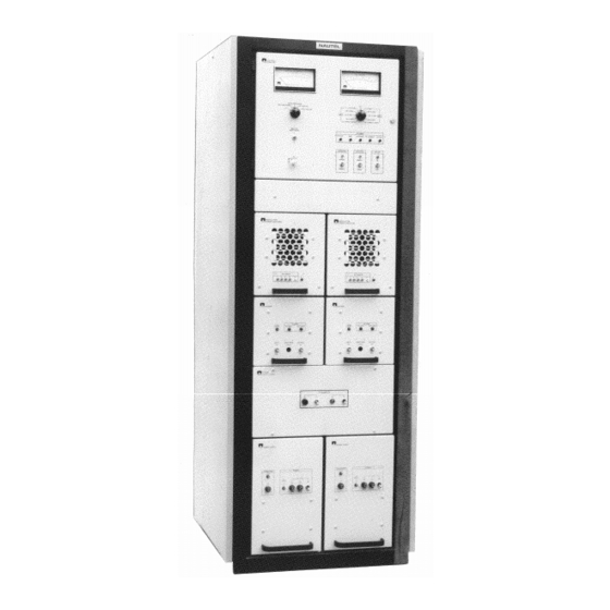
RADIOBEACON TRANSMITTER
Brand:
Nautel
| Category:
Transmitter
| Size: 2.71 MB
Table of Contents
Table of Contents
11
Section
21
1 General Information
21
Introduction
21
Purpose and Scope of Manual
21
Purpose of Equipment
21
Factory Repair Service
21
Mechanical Description
21
Transmitter Chassis
21
Glossary of Terms
22
Number Page
23
ND2000A Radiobeacon Transmitter
23
Number Page
24
Technical Summary
24
Nautel's Identification
26
Glossary of Terms
28
2 Theory of Operation
29
General
29
Transmitter Description
29
Control/Monitor Panel
29
Local/Remote Control
29
Normal\Bypass Control
29
Rf Control Switch
29
Alarm Lamps
30
Battery-Alarm Lamp
30
RF Current-Alarm Lamp
30
SWR-Alarm Lamp
30
Standby-Alarm Lamp
30
Shutdown-Alarm Lamp
30
Select Main Tx Switching
30
Switched Metering
30
Test-Power/Mod Meter/Switch
30
Test Volts/Current Meter/Test Switch
30
Modulator (A2A1)
31
Power Amplifier (A2A2)
31
Exciter Module
32
VDC Regulator
32
Keying/Mod Switch
32
Power Trim
32
Keyer Pwb (A4A1)
33
Rf Oscillator Pwb (A4A3)
34
Crystal Oscillator
34
External RF Drive Input
34
Rf Synthesizer Pwb (A4A3)
34
Rf Drive Amplifier (A4A4)
34
Modulator Driver Pwb (A4A2)
34
2 THEORY of OPERATION (Continued)
35
Section
35
Line Volts Compensation/Power Trim Control
35
PWM Square-Wave Generator
35
Ramp Integrator
35
Linear Attenuator
36
Variable Pulse-Width Generator
36
Balanced Drive
36
Pulse-Width Fault Detector
37
RF Drive Alarm Circuit
37
Power On/Off Panel Assembly
37
Power Supply Modules
37
Power Supply Control Pwb (A7A1)
37
B- VDC to +24 VOLT DC CONVERTER PWB (A7A2)
39
Ac Supply Monitor (A7A3) Assembly
39
HARMONIC FILTER ASSEMBLY (A9) (See
39
Rf Current Probe (A9A1)
39
Fwd/Refl Power Probe (A9A2)
40
RF MON Switching
40
MONITOR PWB (A10) (See Figures SD-12 and
40
Test Switch Control
40
Relay Switching
40
Remote On/Off Relay
40
A/B Main Select
41
Shutdown Relay
41
Standby Relay
41
Monitor +15 Volt DC Regulator
41
Monitor -15 Volts DC Circuit
41
Mod Threshold Circuit
41
Carrier Threshold Circuit
42
Changeover Delay Circuit
42
Standby Circuit
42
Shutdown Circuit
42
Forward Power Cal
43
Audio Monitor Circuit
43
Speaker Control
43
Rf Current Circuit
43
Power Trim Interface Control Circuit
44
Reflected Power/Refl Pwr Cal Circuit
44
Mod% Control Circuit
44
AC POWER MONITOR CIRCUIT (DC Option Installed)
44
AC POWER MONITOR CIRCUIT (DC Option Not Installed)
44
Monitor Bypass Circuit
45
Battery Control Panel (A11) Assembly
45
Battery Control Pwb (A11A1)
45
Low Battery Voltage Monitor
46
Section
51
Mean Level of Ac Power Source
51
Parts Required but Not Supplied
52
Oscillator Crystals
52
Pre-Installation Procedures
52
RF Synthesizer PWB
52
RF Oscillator PWB
52
Crystal Operating Frequencies
52
Keyer Pwb Pre-Installation
53
Keyer Content Configuration
53
Keyed Tone Frequency
54
Keyed Tone Source
54
POWER TRANSFORMERS A7T1 and A8T1 PRIMARY TAP SELECTION
54
Positioning of Selector Plates E1 and E2
56
Installation Procedures
57
Transmitter Module Installation
57
Power Supply Modules A7/A8
57
Modulator/Power Amplifier Modules
57
Exciter Modules
57
External Input/Output Interface Connections
58
Rf Output Cable Connection
58
Lightning/Safety Ground Connection
58
Ac and DC Power Connection
58
First Stage (Initial Start-Up)
59
Second Stage (Initial Start-Up)
59
Third Stage (Initial Start-Up)
60
Intended Carrier Level
60
Rf Monitor Signal Source Selection
60
Intended Modulation Depth
60
External Input/Output Interface
62
Operating Instructions
63
General
63
Emergency Shutdown Procedure
63
Controls and Indicators
63
Control/Monitor Panel Controls and Indicators
63
Power On/Off Panel Controls and Indicators
63
Harmonic Filter Controls
63
Monitor Pwb Controls and Indicators
63
Battery Panel Controls and Indicators
63
Miscellaneous (Cabinet/Interface Panel) Controls and Indicators
64
Prestart-Up Checks
64
Turning on Transmitter
64
Resetting Transmitter
64
Modulation Depth When Using a High 'Q' Antenna
64
4 OPERATING INSTRUCTIONS(Continued)
65
Section
65
Swr-Alarm Indication
65
Remedial Action in Beacon Mode
65
Remedial Action in Voice and Beacon Mode
65
Modulation Percentage Indication
66
Preliminary Switch Settings
66
Control/Monitor Panel Controls and Indicators
67
Modulator/Power Amplifier Module Controls and Indicators
69
Exciter Module Controls and Indicators
70
Power On/Off Panel Controls and Indicators
74
Power Supply Module Controls and Indicators
75
Harmonic Filter Assembly Controls and Indicators
76
Battery Panel Controls and Indicators
79
Miscellaneous (Cabinet/Interface Panel) Controls and Indicators
80
Testing and Adjustment
81
General
81
Operating of Equipment
81
Test/Adjustment Procedures
81
Test/Adjustment Prerequisites
82
Transmitter Turn-On
82
DC Voltage Checks
83
B- Voltage (no Load) Check
83
Logic/Control DC Voltage Checks
83
Carrier Frequency Check
84
RF Oscillator Check
84
Rf Drive Output Level Check
85
Pulse Width Modulation Drive Check
85
Rf Carrier Check
86
Modulation Depth (Mcw) Check
86
RF Monitor
86
B- Voltage (Mcw) Check
87
RF Monitor
87
Modulation Depth (A3E Mode) Check
88
Identification Code Check
89
Standby '1' and Standby '2' Code Checks
89
Fault Thresholds/Changeover Check
90
Preliminary Changeover Procedures
90
Carrier Level Threshold Check
90
Modulation Depth Fault Threshold Check
91
Changeover/Shutdown Check
92
Db to Power/Voltage Conversion
93
Alarm Systems Check
96
RF Current-Alarm Check
97
SWR-Alarm Check
97
Shutdown-Alarm Check
97
Standby-Alarm Check
97
Battery-Alarm Check
97
Mod Drive-Alarm Check
97
RF Drive-Alarm Check
98
Low Ac Power Check
98
Test/Adjustment of Side B
99
Special Adjustment Procedures
99
5 TESTING and ADJUSTMENT (Continued)
101
Section
101
Reflected Power Reading
101
Low Ac Voltage Threshold Adjustment
101
Determination of Low Voltage Battery Threshold
103
Finalization of Low Battery Voltage Threshold Adjustment
103
Operational Adjustment Procedures
104
Operational Adjustment Pre-Requisites
105
Transmitter Turn-On
105
Carrier Level Adjustment
105
Test Equipment
105
Number Page
107
Functional Test/Adjustment Check List
107
Morse Code Characters
111
Maintenance
112
General
112
Electrical Schematics/Logic Diagrams
112
Component Values
112
Logic Symbols
112
Reference Designations
112
Wiring Information
112
Transmitter Cabinet Wiring
112
Modulator/Power Amplifier Module Wiring
112
Exciter Module Wiring
112
Mechanical Drawings
113
Scheduled Maintenance
113
Corrective Maintenance
113
Isolation of Defective Power Mosfets
113
Check of Power Mosfet in Modulator Assembly
114
Check of Power Mosfet in DC-DC Converter Assembly
116
Power Mosfet Replacement
118
Power Mosfet Replacement on Modulator Assemblies
118
Power Mosfet Replacement on Rf Drive Amplifier Assemblies
119
Power Mosfet Replacement on DC-DC Converter Assemblies
119
Carrier Oscillator Frequency - CW
121
Balanced Drive Output - CW
121
Carrier Oscillator - CW
121
Tone Oscillator - CW
122
Audio/Keyed Tone - MCW
122
PWM Ramp Integrator Output - CW
123
Mod Drive (PWM Output) - CW
123
Mod Drive Alarm Condition
123
FWD Power Sample - MCW
123
Manufacturers' Code to Address Index
127
Family Tree - ND2000A 500 Watt Radiobeacon Transmitter
130
Ref des Index - NAC111/02 Control/Monitor Panel
133
Ref des Index - NAPD09/02 Display PWB
134
Ref des Index - NAP13B/02 Modulator/Power Amplifier Module
135
Ref des Index - NASM06/01 Modulator Assembly
137
Ref des Index - NAA02/02 Power Amplifier
138
Ref des Index - NAE45G/02 and /04 Exciter Module
139
Ref des Index - NAPE72 Keyer PWB
140
Ref des Index - NAPE29C/02 Modulator Driver PWB
143
Ref des Index - NAA21A/02 RF Drive Amplifier
150
Ref des Index - NAS25B/03 and NAS25B/04 Power Supply Module
151
Ref des Index - NAPC26C/02 Power Supply Control PWB
152
Ref des Index - NASC01/04 B- VDC to +24 VDC Converter
154
Ref des Index - NAPC32A/01 and NAPC32A/02 AC Supply Monitor PWB
155
Ref des Index - NAF46C/02 Harmonic Filter
156
Ref des Index - NAFP23/02 RF Current Probe
157
Ref des Index - NAFP24A/02 Forward/Reflected Power Probe
158
Ref des Index - NAPC120/02 and NAPC120/04 Monitor PWB
159
Ref des Index - NAX50B/02 Battery Control Panel
166
Wiring Lists Provided
167
Wiring List - ND2000A Transmitter Cabinet
168
Not Used
170
Wiring List - NAC111/02 Control/Monitor Panel
172
Wiring List - NAP13B/02 Modulator/Power Amplifier Module
174
Wiring List - NAE45G/02 and /04 Exciter Module
176
Wiring List - NAS25B/03 and NAS25B/04 Power Supply Modules
179
Wiring List - NASC01/04 B- VDC to +24 VDC Converter
181
Wiring List - NAF46C/02 Harmonic Filter
182
Wiring List - NAFP24A/02 Forward/Reflected Power Probe
183
Wiring List - NAX50B/02 Battery Control Panel
184
Connector Mating Information - Sorted by Floating Connector
187
Advertisement
Advertisement
Related Products
Nautel ND500II
Nautel ND500II-125
Nautel ND500II-113-x21
Nautel ND500II-013-x21
Nautel NX300
Nautel NV30
Nautel NX15
Nautel NV3.5LT
Nautel NX5 AM
Nautel NX3
Nautel Categories
Transmitter
Recording Equipment
Antenna
Industrial Equipment
Security System
More Nautel Manuals
Login
Sign In
OR
Sign in with Facebook
Sign in with Google
Upload manual
Upload from disk
Upload from URL